EP1005949B1 - Verfahren zur Herstellung eines Raketenschubrohres - Google Patents
Verfahren zur Herstellung eines Raketenschubrohres Download PDFInfo
- Publication number
- EP1005949B1 EP1005949B1 EP99309528A EP99309528A EP1005949B1 EP 1005949 B1 EP1005949 B1 EP 1005949B1 EP 99309528 A EP99309528 A EP 99309528A EP 99309528 A EP99309528 A EP 99309528A EP 1005949 B1 EP1005949 B1 EP 1005949B1
- Authority
- EP
- European Patent Office
- Prior art keywords
- tube
- tubes
- tube ends
- predetermined thickness
- metal
- Prior art date
- Legal status (The legal status is an assumption and is not a legal conclusion. Google has not performed a legal analysis and makes no representation as to the accuracy of the status listed.)
- Expired - Lifetime
Links
- 238000000034 method Methods 0.000 title claims description 11
- 239000002184 metal Substances 0.000 claims description 41
- 238000004519 manufacturing process Methods 0.000 claims description 14
- 238000003754 machining Methods 0.000 claims description 12
- 230000013011 mating Effects 0.000 claims description 9
- 238000005507 spraying Methods 0.000 claims description 8
- 238000001816 cooling Methods 0.000 description 6
- 230000000712 assembly Effects 0.000 description 4
- 238000000429 assembly Methods 0.000 description 4
- 239000007921 spray Substances 0.000 description 3
- 238000005219 brazing Methods 0.000 description 2
- 239000002826 coolant Substances 0.000 description 2
- 239000000463 material Substances 0.000 description 2
- 239000003380 propellant Substances 0.000 description 2
- 238000003466 welding Methods 0.000 description 2
- 229910000851 Alloy steel Inorganic materials 0.000 description 1
- 229910000831 Steel Inorganic materials 0.000 description 1
- 230000015572 biosynthetic process Effects 0.000 description 1
- 238000002788 crimping Methods 0.000 description 1
- 238000010304 firing Methods 0.000 description 1
- 239000012530 fluid Substances 0.000 description 1
- 238000010438 heat treatment Methods 0.000 description 1
- 238000001513 hot isostatic pressing Methods 0.000 description 1
- 239000010959 steel Substances 0.000 description 1
- 230000002459 sustained effect Effects 0.000 description 1
Images




Classifications
-
- B—PERFORMING OPERATIONS; TRANSPORTING
- B23—MACHINE TOOLS; METAL-WORKING NOT OTHERWISE PROVIDED FOR
- B23P—METAL-WORKING NOT OTHERWISE PROVIDED FOR; COMBINED OPERATIONS; UNIVERSAL MACHINE TOOLS
- B23P15/00—Making specific metal objects by operations not covered by a single other subclass or a group in this subclass
-
- B—PERFORMING OPERATIONS; TRANSPORTING
- B23—MACHINE TOOLS; METAL-WORKING NOT OTHERWISE PROVIDED FOR
- B23P—METAL-WORKING NOT OTHERWISE PROVIDED FOR; COMBINED OPERATIONS; UNIVERSAL MACHINE TOOLS
- B23P15/00—Making specific metal objects by operations not covered by a single other subclass or a group in this subclass
- B23P15/008—Rocket engine parts, e.g. nozzles, combustion chambers
-
- F—MECHANICAL ENGINEERING; LIGHTING; HEATING; WEAPONS; BLASTING
- F02—COMBUSTION ENGINES; HOT-GAS OR COMBUSTION-PRODUCT ENGINE PLANTS
- F02K—JET-PROPULSION PLANTS
- F02K9/00—Rocket-engine plants, i.e. plants carrying both fuel and oxidant therefor; Control thereof
- F02K9/97—Rocket nozzles
- F02K9/972—Fluid cooling arrangements for nozzles
-
- F—MECHANICAL ENGINEERING; LIGHTING; HEATING; WEAPONS; BLASTING
- F02—COMBUSTION ENGINES; HOT-GAS OR COMBUSTION-PRODUCT ENGINE PLANTS
- F02K—JET-PROPULSION PLANTS
- F02K9/00—Rocket-engine plants, i.e. plants carrying both fuel and oxidant therefor; Control thereof
- F02K9/97—Rocket nozzles
- F02K9/974—Nozzle- linings; Ablative coatings
-
- Y—GENERAL TAGGING OF NEW TECHNOLOGICAL DEVELOPMENTS; GENERAL TAGGING OF CROSS-SECTIONAL TECHNOLOGIES SPANNING OVER SEVERAL SECTIONS OF THE IPC; TECHNICAL SUBJECTS COVERED BY FORMER USPC CROSS-REFERENCE ART COLLECTIONS [XRACs] AND DIGESTS
- Y10—TECHNICAL SUBJECTS COVERED BY FORMER USPC
- Y10T—TECHNICAL SUBJECTS COVERED BY FORMER US CLASSIFICATION
- Y10T29/00—Metal working
- Y10T29/49—Method of mechanical manufacture
- Y10T29/49346—Rocket or jet device making
-
- Y—GENERAL TAGGING OF NEW TECHNOLOGICAL DEVELOPMENTS; GENERAL TAGGING OF CROSS-SECTIONAL TECHNOLOGIES SPANNING OVER SEVERAL SECTIONS OF THE IPC; TECHNICAL SUBJECTS COVERED BY FORMER USPC CROSS-REFERENCE ART COLLECTIONS [XRACs] AND DIGESTS
- Y10—TECHNICAL SUBJECTS COVERED BY FORMER USPC
- Y10T—TECHNICAL SUBJECTS COVERED BY FORMER US CLASSIFICATION
- Y10T29/00—Metal working
- Y10T29/49—Method of mechanical manufacture
- Y10T29/4935—Heat exchanger or boiler making
-
- Y—GENERAL TAGGING OF NEW TECHNOLOGICAL DEVELOPMENTS; GENERAL TAGGING OF CROSS-SECTIONAL TECHNOLOGIES SPANNING OVER SEVERAL SECTIONS OF THE IPC; TECHNICAL SUBJECTS COVERED BY FORMER USPC CROSS-REFERENCE ART COLLECTIONS [XRACs] AND DIGESTS
- Y10—TECHNICAL SUBJECTS COVERED BY FORMER USPC
- Y10T—TECHNICAL SUBJECTS COVERED BY FORMER US CLASSIFICATION
- Y10T29/00—Metal working
- Y10T29/49—Method of mechanical manufacture
- Y10T29/4998—Combined manufacture including applying or shaping of fluent material
- Y10T29/49982—Coating
Definitions
- This invention is related to rocket engines, and particularly to a process for forming manifolds for rocket engine thrust chambers.
- Rocket engines such as those used to launch satellites, are costly to design and manufacture. At the same time the demand for rocket engines capable of carrying payloads to space or near-Earth orbits continues to grow. Consequently, manufacturers of such rocket engines are constantly seeking new ways to reduce the design and manufacturing costs of producing rocket engine components.
- One such component is the rocket thrust chamber within which the propellants of the rocket engine are combusted and accelerated. Because of the extremely high temperatures of the propellants moving through the thrust chamber, the walls of the thrust chamber must be cooled in those applications that require sustained engine firings. Such cooling is typically accomplished by flowing a coolant through tubes that form the inner wall of the thrust chamber.
- European Patent Application EP 0 780 563 A2 discloses a method of making rocket thrust chamber comprising a number of tubes forming a tube bundle according to the preamble of claim 1. Since the manufacture of such thrust chambers is costly, novel ways of manufacturing such thrust chambers have been developed.
- U.S. Pat. No. 5,375,325 to Bales et al. discloses a rocket chamber produced by positioning sleeved cooling tubes within a structural jacket to form a tube bundle, and positioning a liner within the tube bundle thereby sandwiching the tubes between the jacket and the liner.
- the tubes are then subjected to high internal pressure and inflated at high temperature while the liner is simultaneously subjected to the same high pressure, thereby forcing the sleeved tubes into intimate contact with adjacent sleeved tubes, the liner and the jacket.
- the temperature is maintained until bonding has occurred between the liner, sleeved tubes and jacket.
- Another object of the present invention to provide a method for forming a rocket thrust chamber which eliminates the need for each end of each of the tubes to be individually welded into manifold channels in the jacket.
- a method of making a rocket thrust chamber in which molten metal is sprayed onto the outer shell of a cooling tube bundle, and the ends of tubes are covered with predetermined thicknesses of the metal. Circumferentially extending manifold channels that intersect each of the tube ends are then machined into the predetermined thicknesses in of metal, and mating assemblies are attached to enclose the manifold channels.
- a spray of molten metal onto a tube bundle 10 such as the one shown in the sectional view of Fig. 1.
- This metal spraying process is commonly referred to as Vacuum Plasma Spray ("VPS") by those skilled in the art
- VPS Vacuum Plasma Spray
- Fig. 1 shows only 1 ⁇ 4 of the tube bundle 10, and that the entire tube bundle 10 is symmetric about a longitudinally extending reference axis 12.
- the tube bundle 10 includes a plurality of cooling tubes 14 that are circumferentially located about a longitudinally extending reference axis 12.
- the longitudinal axis 12 defines the axis of symmetry for the tube bundle 10, and, as shown in Fig. 1, each of the tubes extends along the longitudinal axis 12 in spaced relation thereto.
- Each of the tubes 14 is bonded to two of the tubes 14 immediately adjacent thereto along the entire length 16 which the tubes 14 extend along the longitudinal axis 12. This bonding, which is preferably accomplished by brazing, fills the interstices between adjacent tubes 14, thereby preventing the spray of molten metal from infiltrating into the interior of the tube bundle 10 during the metal spraying process described below.
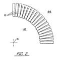
- Each of the tubes 14 has a first tube end 18 and a second tube end 20, and each of the first tube ends is in spaced relation to each of the other first tube ends, as shown in Fig. 2.
- each of the second tube ends 20 is in spaced relation to each of the other second tube ends 20 (not shown).
- each of the first tube ends 18 is located radially outward of a first segment 22 of the longitudinal axis 12, and each of the second tube ends 20 is located radially outward of a second segment 24 of the longitudinal axis 12.
- the outer surface 26 of each of the tubes 14 comprises a radially inward portion 28 and a radially outward portion 30.
- the radially inward portion 28 of each tube 14 faces the longitudinal axis 12 and the radially outward portion 30 of each tube 14 faces away from the longitudinal axis 12.
- the radially outward portions 30 define the tube bundle outer shell 32.
- a first structural ring 34 is secured to the first tube ends 18, and a second structural ring 36 is secured to the second tube ends 20 such that tube bundle 10 is sandwiched between the first and second structural rings 34, 36, as shown in Fig. 1.
- the structural rings 34, 36 are made of the same metal that is used in the spraying process described below, and each of the structural rings 34, 36 is preferably secured to the immediately adjacent tube ends 18, 20 by brazing.
- a lid 38, 40 is secured to each of the structural rings 34, 36, thereby isolating the inner cavity 42 of the tube bundle 10 from the ambient environment 44, as shown in Fig. 2.
- Each of the first and second tube ends 18, 20 is then sealed, preferably by crimping each tube end 18, 20 and folding it back onto its respective tube 14, thereby defining a sealed tip 46, 48 at each of the first and second tube ends 18, 20, as shown in Fig. 3.
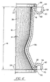
- the tube bundle 10, with the attached rings 34, 36 and lids 38, 40, is then placed into a VPS chamber of the type known in the art, and molten metal, preferably steel or a steel alloy, is sprayed onto the tube bundle outer shell 32 and the first and second tube ends 18, 20, until a first predetermined thickness 50 of the metal covers the tube bundle outer shell 32, as shown in Fig. 4.
- Additional amounts of molten metal are then sprayed onto the first tube ends 18 until a second predetermined thickness 52 of metal covers the first tube ends 18, and additional amounts of molten metal are sprayed onto the second tube ends 20 until a third predetermined thickness 54 of metal covers the second tube ends 20.
- the resulting structural jacket 56 as shown in Fig. 6, includes circumferentially extending inlet and outlet manifold channels 60, 64.
- the inlet manifold channel 60 is bounded by inlet manifold lands 66, 68
- the outlet manifold channel 64 is bounded by outlet manifold lands 70, 72, as shown in Fig. 6.
- a first mating assembly 74 which has been machined to fit the inlet manifold lands 66, 68 is sealingly attached to the inlet manifold lands 66, 68 of the second predetermined thickness 52 of metal
- a second mating assembly 76 which has been machined to fit the outlet manifold lands 70, 72, is sealingly attached to the third predetermined thickness 54 of metal.
- the mating assemblies 74, 76 which are made of the same metal as the jacket 56, preferably are sealingly attached to the jacket 56 by welding the mating assemblies 74, 76 to the manifold lands 60, 68, 70, 72 immediately adjacent thereto. Once the circumferential channels 60, 64 have been enclosed by the mating assemblies 74, 76, fluid, such as coolant, can only enter or exit the cooling tubes 14 through orifices (not shown) in the manifolds.
- the method of the present invention requires less machining than the prior art to form a structural jacket,, since only the outer surface of the structural jacket needs to be machined. Furthermore, the need to individually weld each of the cooling tubes into the manifold channels in the jacket is eliminated, since the molten metal sprayed onto the tube ends during the jacket formation seals each of the tube ends to the structural jacket. Accordingly, the time and effort, and the attendant cost, necessary to manufacture the thrust chamber is reduced as compared to the prior art.
Landscapes
- Engineering & Computer Science (AREA)
- Mechanical Engineering (AREA)
- Chemical & Material Sciences (AREA)
- Combustion & Propulsion (AREA)
- General Engineering & Computer Science (AREA)
- Coating By Spraying Or Casting (AREA)
Claims (1)
- Verfahren zum Herstellen einer Raketenschubkammer, wobei das Verfahren aufweist:dadurch gekennzeichnet, dass vor dem Aufsprühen des geschmolzenen Metalls auf das Rohrbündel die ersten und die zweiten Rohrenden (18, 20) abgedichtet werden, um so eine dichte Spitze (46, 48) an jedem der ersten und zweiten Rohrenden (18, 20) zu definieren,Bereitstellen eines Rohrbündels (10), aufweisend eine Mehrzahl von Rohren (14), wobei das Rohrbündel (10) eine dort hindurch definierte Längsachse (12) hat, wobei jedes der Rohre (14) sich entlang der Längsachse in einer beabstandeten Relation zu dieser erstreckt, wobei jedes der Rohre (14) mit zwei der Rohre (14), die diesem unmittelbar benachbart sind, entlang einer ersten Länge, über die sich die Rohre (14) entlang der Achse (12) erstrecken, verbunden ist, wobei jedes der Rohre (14) ein erstes Rohrende (18) und ein zweites Rohrende (20) hat, wobei jedes der ersten Rohrenden (18) sich in beabstandeter Relation zu jedem der anderen ersten Rohrenden befindet und radial nach außen von einem ersten Segment (22) von der Bezugsachse (12) angeordnet ist, und wobei jedes der zweiten Rohrenden (20) sich in beabstandeter Relation zu jedem der anderen zweiten Rohrenden (20) befindet und radial nach außen von einem zweiten Segment (24) von der Bezugsachse (12) angeordnet ist, wobei die äußere Oberfläche (26) eines jeden Rohr (14) einen radial inneren Bereich (28) und einen radial äußeren Bereich (30) aufweist, wobei der radial innere Bereich (28) eines jeden Rohrs (14) in Richtung zur Achse (12) gerichtet ist und der radial äußere Bereich (30) eines jeden Rohrs (14) weg von der Achse (12) gerichtet ist, wobei die radial äußeren Bereiche gemeinsam eine äußere Schale (32) des Rohrbündels definieren,Aufsprühen von geschmolzenem Metall auf die äußere Schale (32) des Rohrbündels und des ersten und des zweiten Rohrendes (18, 20), bis eine erste vorbestimmte Dicke (50) des Metalls die äußere Schale (32) des Rohrbündels überdeckt,
weiterhin dadurch gekennzeichnet, dass nach dem Aufsprühen des geschmolzenen Metalls auf das Rohrbündel die folgenden Schritte ausgeführt werden:
Aufsprühen von zusätzlichen Mengen an geschmolzenem Material auf die ersten Rohrenden (18), bis eine zweite vorbestimmte Dicke (52) aus Metall die ersten Rohrenden (18) überdeckt,
Aufsprühen einer zusätzlichen Menge von geschmolzenem Metall auf die zweiten Rohrenden (20), bis eine dritte vorbestimmte Dicke (54) die zweiten Rohrenden (20) überdeckt,
Ausbilden eines ersten umfangsmäßigen Kanals (60) in der zweiten vorbestimmten Dicke (52) aus Metall durch Wegbearbeiten von etwas von der zweiten vorbestimmten Dicke aus Metall und der abgedichteten Spitze (46) von jedem der ersten Rohrenden (18), und Ausbilden eines zweiten umfangsmäßigen Kanals (62) in der dritten vorbestimmten Dicke (54) aus Metall durch Wegbearbeiten von etwas von der dritten vorbestimmten Dicke aus Metall und der abgedichteten Spitze (48) von jedem der zweiten Rohrenden (20);
Schließen des ersten umfangsmäßigen Kanals (60) durch dichtes Anbringen einer ersten Passanordnung (74) an der zweiten vorbestimmten Dicke aus Metall (52) und Schließen des zweiten umfangsmäßigen Kanals (64) durch dichtes Anbringen einer zweiten Passanordnung (76) an der dritten vorbestimmten Dicke aus Metall.
Applications Claiming Priority (2)
| Application Number | Priority Date | Filing Date | Title |
|---|---|---|---|
| US201516 | 1998-11-30 | ||
| US09/201,516 US6134782A (en) | 1998-11-30 | 1998-11-30 | Method of forming a rocket thrust chamber |
Publications (2)
| Publication Number | Publication Date |
|---|---|
| EP1005949A1 EP1005949A1 (de) | 2000-06-07 |
| EP1005949B1 true EP1005949B1 (de) | 2003-06-11 |
Family
ID=22746149
Family Applications (1)
| Application Number | Title | Priority Date | Filing Date |
|---|---|---|---|
| EP99309528A Expired - Lifetime EP1005949B1 (de) | 1998-11-30 | 1999-11-29 | Verfahren zur Herstellung eines Raketenschubrohres |
Country Status (5)
| Country | Link |
|---|---|
| US (1) | US6134782A (de) |
| EP (1) | EP1005949B1 (de) |
| JP (1) | JP2000161141A (de) |
| KR (1) | KR100577133B1 (de) |
| DE (1) | DE69908739T2 (de) |
Families Citing this family (15)
| Publication number | Priority date | Publication date | Assignee | Title |
|---|---|---|---|---|
| SE512942C2 (sv) * | 1998-10-02 | 2000-06-12 | Volvo Aero Corp | Förfarande för tillverkning av utloppsmunstycken för raketmotorer |
| US6421998B1 (en) * | 2000-06-13 | 2002-07-23 | The Boeing Company | Thruster device responsive to solar radiation |
| US6688100B1 (en) * | 2002-07-16 | 2004-02-10 | The Boeing Company | Combustion chamber having a multiple-piece liner and associated assembly method |
| US7051513B2 (en) * | 2003-06-06 | 2006-05-30 | United Technologies Corporation | Rocket engine tubular chamber with single piece jacket |
| US7219505B2 (en) * | 2004-10-22 | 2007-05-22 | York International Corporation | Control stability system for moist air dehumidification units and method of operation |
| DE102007048527B4 (de) * | 2007-10-10 | 2014-03-27 | Bayern-Chemie Gesellschaft Für Flugchemische Antriebe Mbh | Schubtriebwerk |
| FR2963063B1 (fr) * | 2010-07-26 | 2015-11-27 | Snecma | Chambre de combustion munie d'un element tubulaire |
| CN103028894B (zh) * | 2011-09-29 | 2015-07-01 | 西安航空动力股份有限公司 | 航空发动机加力喷杆的加工方法和定位芯棒 |
| CN105479103B (zh) * | 2015-11-30 | 2018-03-09 | 湖北三江航天江北机械工程有限公司 | 薄壁花瓶状冷却室的加工方法 |
| DE102016215244A1 (de) * | 2016-08-16 | 2018-02-22 | Airbus Ds Gmbh | Brennkammerstruktur, insbesondere für ein raketentriebwerk |
| CN109352273B (zh) * | 2018-11-05 | 2020-02-14 | 首都航天机械有限公司 | 一种针对吊耳高精度装配与接口检测协调方法 |
| CN110202320B (zh) * | 2019-03-15 | 2024-06-04 | 蓝箭航天技术有限公司 | 用于推力室制备工艺的复合工装及推力室制备工艺 |
| CN112296611B (zh) * | 2020-11-16 | 2022-06-10 | 遵义航天新力精密铸锻有限公司 | 航空航天发射器的喷管壳加工工艺 |
| CN113787307B (zh) * | 2021-09-09 | 2022-07-26 | 西安远航真空钎焊技术有限公司 | 一种收扩管段工件的加工方法 |
| CN113982786B (zh) * | 2021-10-29 | 2023-06-06 | 中国人民解放军战略支援部队航天工程大学 | 规避异种金属焊接的紫铜-不锈钢的火箭发动机推力室 |
Family Cites Families (10)
| Publication number | Priority date | Publication date | Assignee | Title |
|---|---|---|---|---|
| US3782118A (en) * | 1972-12-18 | 1974-01-01 | Messerschmitt Boelkow Blohm | Regeneratively cooled thrust gas generator construction and method of making same |
| JPS6082603A (ja) * | 1983-10-07 | 1985-05-10 | Natl Aerospace Lab | ロケツト燃焼器製作法 |
| FR2669966B1 (fr) * | 1990-11-30 | 1993-03-26 | Europ Propulsion | Procede de fabrication de paroi de chambre de combustion, notamment pour moteur-fusee, et chambre de combustion obtenue par ce procede. |
| US5386628A (en) * | 1991-12-23 | 1995-02-07 | United Technologies Corporation | Method of making a diffusion bonded rocket chamber |
| US5249357A (en) * | 1993-01-27 | 1993-10-05 | The United States Of America As Represented By The Administrator Of The National Aeronautics And Space Administration | Method of fabricating a rocket engine combustion chamber |
| US5473817A (en) * | 1993-12-21 | 1995-12-12 | United Technologies Corporation | Method of making cooled rocket combustion chamber construction |
| US5477613A (en) * | 1993-12-21 | 1995-12-26 | United Technologies Corporation | Method of simultaneously forming rocket thrust chamber cooling tubes |
| WO1995029785A1 (en) * | 1994-04-29 | 1995-11-09 | United Technologies Corporation | Fabrication of tubular wall thrust chambers for rocket engines using laser powder injection |
| US5546656A (en) * | 1994-11-30 | 1996-08-20 | United Technologies Corporation | Fabrication of rocket thrust chambers |
| US5832719A (en) * | 1995-12-18 | 1998-11-10 | United Technologies Corporation | Rocket thrust chamber |
-
1998
- 1998-11-30 US US09/201,516 patent/US6134782A/en not_active Expired - Lifetime
-
1999
- 1999-11-26 KR KR1019990052948A patent/KR100577133B1/ko not_active Expired - Fee Related
- 1999-11-26 JP JP11336051A patent/JP2000161141A/ja not_active Ceased
- 1999-11-29 DE DE69908739T patent/DE69908739T2/de not_active Expired - Lifetime
- 1999-11-29 EP EP99309528A patent/EP1005949B1/de not_active Expired - Lifetime
Also Published As
| Publication number | Publication date |
|---|---|
| KR20000067815A (ko) | 2000-11-25 |
| EP1005949A1 (de) | 2000-06-07 |
| US6134782A (en) | 2000-10-24 |
| JP2000161141A (ja) | 2000-06-13 |
| KR100577133B1 (ko) | 2006-05-09 |
| DE69908739D1 (de) | 2003-07-17 |
| DE69908739T2 (de) | 2003-12-24 |
Similar Documents
| Publication | Publication Date | Title |
|---|---|---|
| EP1005949B1 (de) | Verfahren zur Herstellung eines Raketenschubrohres | |
| RU2268387C2 (ru) | Камера сгорания реактивного двигателя с несущими элементами, имеющими форму горловины сопла и собранными из конформных секций, и способ изготовления такой камеры сгорания | |
| US5613299A (en) | Method of fabricating a rocket thrust chamber | |
| US5701670A (en) | Method of making rocket engine combustion chamber utilizing "slide in" port liner | |
| US5386628A (en) | Method of making a diffusion bonded rocket chamber | |
| US4270256A (en) | Manufacture of composite turbine rotors | |
| US6205661B1 (en) | Method of making a rocket thrust chamber | |
| US5371945A (en) | Method of making a tubular combustion chamber construction | |
| US8127443B2 (en) | Method of fabricating a rocket engine nozzle using pressure brazing | |
| JP4000129B2 (ja) | ロケットエンジン燃焼室およびその形成方法 | |
| US5473817A (en) | Method of making cooled rocket combustion chamber construction | |
| US6164060A (en) | Combustion chamber/nozzle assembly and fabrication process therefor | |
| US5477613A (en) | Method of simultaneously forming rocket thrust chamber cooling tubes | |
| EP0720876B1 (de) | Herstellung von Raketenkammern | |
| GB2249141A (en) | Thrust nozzle wall construction. | |
| EP1382403B1 (de) | Verfahren zum Herstellen eines Elements mit einer aus Rohren bestehenden Wand | |
| GB2063721A (en) | Method of bonding composite turbine wheels | |
| EP1352168B1 (de) | Raketentriebwerksglied und verfahren zur herstellung eines raketentriebwerksglieds | |
| GB1256129A (en) | Improvements in feed or discharge collector rings for thrust nozzles or combustion chambers of rocket propulsion units | |
| RU2109606C1 (ru) | Способ изготовления паяных телескопических конструкций | |
| US6131280A (en) | Method of repairing a rocket thrust chamber | |
| RU2096143C1 (ru) | Способ пайки телескопических конструкций |
Legal Events
| Date | Code | Title | Description |
|---|---|---|---|
| PUAI | Public reference made under article 153(3) epc to a published international application that has entered the european phase |
Free format text: ORIGINAL CODE: 0009012 |
|
| AK | Designated contracting states |
Kind code of ref document: A1 Designated state(s): DE FR GB |
|
| AX | Request for extension of the european patent |
Free format text: AL;LT;LV;MK;RO;SI |
|
| 17P | Request for examination filed |
Effective date: 20001130 |
|
| AKX | Designation fees paid |
Free format text: DE FR GB |
|
| 17Q | First examination report despatched |
Effective date: 20020410 |
|
| GRAH | Despatch of communication of intention to grant a patent |
Free format text: ORIGINAL CODE: EPIDOS IGRA |
|
| GRAH | Despatch of communication of intention to grant a patent |
Free format text: ORIGINAL CODE: EPIDOS IGRA |
|
| GRAA | (expected) grant |
Free format text: ORIGINAL CODE: 0009210 |
|
| AK | Designated contracting states |
Designated state(s): DE FR GB |
|
| REG | Reference to a national code |
Ref country code: GB Ref legal event code: FG4D |
|
| REF | Corresponds to: |
Ref document number: 69908739 Country of ref document: DE Date of ref document: 20030717 Kind code of ref document: P |
|
| ET | Fr: translation filed | ||
| PLBE | No opposition filed within time limit |
Free format text: ORIGINAL CODE: 0009261 |
|
| STAA | Information on the status of an ep patent application or granted ep patent |
Free format text: STATUS: NO OPPOSITION FILED WITHIN TIME LIMIT |
|
| 26N | No opposition filed |
Effective date: 20040312 |
|
| PGFP | Annual fee paid to national office [announced via postgrant information from national office to epo] |
Ref country code: FR Payment date: 20081106 Year of fee payment: 10 |
|
| REG | Reference to a national code |
Ref country code: FR Ref legal event code: ST Effective date: 20100730 |
|
| PG25 | Lapsed in a contracting state [announced via postgrant information from national office to epo] |
Ref country code: FR Free format text: LAPSE BECAUSE OF NON-PAYMENT OF DUE FEES Effective date: 20091130 |
|
| PGFP | Annual fee paid to national office [announced via postgrant information from national office to epo] |
Ref country code: DE Payment date: 20121121 Year of fee payment: 14 |
|
| PGFP | Annual fee paid to national office [announced via postgrant information from national office to epo] |
Ref country code: GB Payment date: 20121128 Year of fee payment: 14 |
|
| GBPC | Gb: european patent ceased through non-payment of renewal fee |
Effective date: 20131129 |
|
| REG | Reference to a national code |
Ref country code: DE Ref legal event code: R119 Ref document number: 69908739 Country of ref document: DE Effective date: 20140603 |
|
| PG25 | Lapsed in a contracting state [announced via postgrant information from national office to epo] |
Ref country code: DE Free format text: LAPSE BECAUSE OF NON-PAYMENT OF DUE FEES Effective date: 20140603 |
|
| PG25 | Lapsed in a contracting state [announced via postgrant information from national office to epo] |
Ref country code: GB Free format text: LAPSE BECAUSE OF NON-PAYMENT OF DUE FEES Effective date: 20131129 |