EP1005396B1 - Hutch chamber for jig - Google Patents
Hutch chamber for jig Download PDFInfo
- Publication number
- EP1005396B1 EP1005396B1 EP98938535A EP98938535A EP1005396B1 EP 1005396 B1 EP1005396 B1 EP 1005396B1 EP 98938535 A EP98938535 A EP 98938535A EP 98938535 A EP98938535 A EP 98938535A EP 1005396 B1 EP1005396 B1 EP 1005396B1
- Authority
- EP
- European Patent Office
- Prior art keywords
- reciprocating
- hutch
- screen
- wall portion
- jig
- Prior art date
- Legal status (The legal status is an assumption and is not a legal conclusion. Google has not performed a legal analysis and makes no representation as to the accuracy of the status listed.)
- Expired - Lifetime
Links
- 239000000463 material Substances 0.000 claims description 16
- 239000012141 concentrate Substances 0.000 claims description 12
- 230000002093 peripheral effect Effects 0.000 claims description 6
- 230000005484 gravity Effects 0.000 claims description 5
- 238000000034 method Methods 0.000 claims description 4
- 230000009471 action Effects 0.000 claims description 3
- 230000004913 activation Effects 0.000 claims description 2
- 230000000916 dilatatory effect Effects 0.000 claims description 2
- 239000012530 fluid Substances 0.000 claims description 2
- XLYOFNOQVPJJNP-UHFFFAOYSA-N water Substances O XLYOFNOQVPJJNP-UHFFFAOYSA-N 0.000 description 15
- 238000004140 cleaning Methods 0.000 description 5
- 230000010349 pulsation Effects 0.000 description 5
- 239000002002 slurry Substances 0.000 description 5
- 239000002245 particle Substances 0.000 description 4
- 230000010339 dilation Effects 0.000 description 3
- 230000007246 mechanism Effects 0.000 description 3
- 239000007921 spray Substances 0.000 description 3
- 230000008901 benefit Effects 0.000 description 2
- 230000009467 reduction Effects 0.000 description 2
- 229910000838 Al alloy Inorganic materials 0.000 description 1
- 238000009825 accumulation Methods 0.000 description 1
- 238000005266 casting Methods 0.000 description 1
- 238000010276 construction Methods 0.000 description 1
- 230000008878 coupling Effects 0.000 description 1
- 238000010168 coupling process Methods 0.000 description 1
- 238000005859 coupling reaction Methods 0.000 description 1
- 230000003247 decreasing effect Effects 0.000 description 1
- 239000005355 lead glass Substances 0.000 description 1
- 238000012423 maintenance Methods 0.000 description 1
- 238000004519 manufacturing process Methods 0.000 description 1
- 239000000203 mixture Substances 0.000 description 1
- 230000004048 modification Effects 0.000 description 1
- 238000012986 modification Methods 0.000 description 1
Images
Classifications
-
- B—PERFORMING OPERATIONS; TRANSPORTING
- B03—SEPARATION OF SOLID MATERIALS USING LIQUIDS OR USING PNEUMATIC TABLES OR JIGS; MAGNETIC OR ELECTROSTATIC SEPARATION OF SOLID MATERIALS FROM SOLID MATERIALS OR FLUIDS; SEPARATION BY HIGH-VOLTAGE ELECTRIC FIELDS
- B03B—SEPARATING SOLID MATERIALS USING LIQUIDS OR USING PNEUMATIC TABLES OR JIGS
- B03B5/00—Washing granular, powdered or lumpy materials; Wet separating
- B03B5/02—Washing granular, powdered or lumpy materials; Wet separating using shaken, pulsated or stirred beds as the principal means of separation
- B03B5/10—Washing granular, powdered or lumpy materials; Wet separating using shaken, pulsated or stirred beds as the principal means of separation on jigs
- B03B5/12—Washing granular, powdered or lumpy materials; Wet separating using shaken, pulsated or stirred beds as the principal means of separation on jigs using pulses generated mechanically in fluid
- B03B5/16—Diaphragm jigs
-
- B—PERFORMING OPERATIONS; TRANSPORTING
- B03—SEPARATION OF SOLID MATERIALS USING LIQUIDS OR USING PNEUMATIC TABLES OR JIGS; MAGNETIC OR ELECTROSTATIC SEPARATION OF SOLID MATERIALS FROM SOLID MATERIALS OR FLUIDS; SEPARATION BY HIGH-VOLTAGE ELECTRIC FIELDS
- B03B—SEPARATING SOLID MATERIALS USING LIQUIDS OR USING PNEUMATIC TABLES OR JIGS
- B03B5/00—Washing granular, powdered or lumpy materials; Wet separating
- B03B5/02—Washing granular, powdered or lumpy materials; Wet separating using shaken, pulsated or stirred beds as the principal means of separation
- B03B5/10—Washing granular, powdered or lumpy materials; Wet separating using shaken, pulsated or stirred beds as the principal means of separation on jigs
- B03B5/22—Washing granular, powdered or lumpy materials; Wet separating using shaken, pulsated or stirred beds as the principal means of separation on jigs using pulses generated by liquid injection
Definitions
- This invention relates to jigs which separate materials in a feed mixture on the basis of differing specific gravities and especially, but not exclusively, to centrifugal jigs of the general type described in International Patent Publication Nos. WO86/04269 and WO90/00090, in which a feed slurry is introduced into a rotating chamber bounded radially by a screen provided with ragging on its inner surface, the ragging being dilated repetitively to provide jigging action.
- the ragging is dilated by pulsing the water in a hutch chamber which surrounds the screen.
- the water is pulsed by means of a diaphragm positioned at the base of the hutch chamber.
- a number ofhutch chambers are circumferentially spaced about the jig screen, with the water in the hutch chambers being pulsed sequentially.
- Each hutch chamber has a diaphragm positioned below the screen, with the diaphragms being actuated by respective pushrods driven by a central crank assembly.
- the present invention seeks to provide an improved pulsating mechanism for a jig.
- centrifugal jig having a container mounted for rotation about a longitudinal axis thereof, the container having an axial region, a peripheral region including one or more hutch chambers separated from the axial region by screen means, means for introducing feed material to the axial region and means for pulsating fluid in said peripheral region so as to respectively dilate a ragging material restrained by said screen means, characterised in that the pulsating means is located directly radially outwards of said screen means and includes a reciprocating radially outer wall portion of the respective hutch chamber, each reciprocating wall portion including a concentrate outlet and a convergent wall surface leading thereto.
- the peripheral region includes a plurality of said hutch chambers circumferentially spaced about said axis, each hutch chamber having respective reciprocating device means for actuating the respective reciprocating wall portion.
- the reciprocating drive means includes a lever driven by a respective pushrod, and crank means for reciprocating each of the pushrods.
- each reciprocating wall portion is biased to non-pulsating position by centrifugal motion of the jig.
- each reciprocating wall portion includes a diaphragm with a support block.
- each reciprocating wall portion reciprocates along a substantially radial line of action which intersects with the screen.
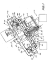
- Fig 1 shows a centrifugal jig of the general type according to the Applicant's WO90/00090 but employing a pulsion mechanism according to the present invention.
- the general construction and operation of the jig are described in detail in that patent.
- the centrifugal jig of Fig. 1 has a frame 10 supporting a jig drive motor 12, a crank drive motor 13, a fixed launder arrangement 14 and cover 16 and a jig main shaft 18 which is supported in bearings 20 to rotate about a rotational axis 22.
- the main shaft 18 is driven by the jig drive motor 12 through jig drive pulley 24 and jig drive belt 26.
- a screen housing 28 supporting a screen 30 defining an inner chamber 32 and a number of hutch chambers 34 circumferentially spaced about the screen.
- a crankshaft 36 mounted inside the jig main shaft for independent rotation in bearings 35 is a crankshaft 36 with crank 38 for reciprocating a respective pushrod 40 for each hutch chamber.
- Ragging material 41 (shown in Fig. 2), such as run-of-mill gamet, aluminium alloy or lead glass balls, is provided on the inner surface of the screen 30.
- the ragging is held against the surface of the screen due to the rotation of the jig.
- the feed slurry entering the inner chamber 32 through the feed tube 42 migrates to the inner surface of the ragging.
- Hutch water is supplied to tube 43, passing through bores (not shown) in the screen housing 30, into each of the hutch chambers 34 circumferentially spaced about the screen.
- the crank 38 sequentially reciprocates a series of radially extending pushrods 40, with each pushrod in turn reciprocating a respective hutch chamber 34, as will be described below with reference to Fig. 2.
- the reciprocation of the hutches causes pulsation of the water in the respective hutches.
- the ragging is repetitively dilated by the pulsation of the hutch water. This dilation allows the higher specific gravity material in the feed slurry to pass through the ragging and the screen and enter the hutch chambers.
- the concentrate material then travels along the convergent walls 45 of the hutch to the radially outermost part of the hutch chamber and passes through concentrate outlet spigot 44, which is aligned with a gap in the inner wall of a concentrate launder 46.
- the lower specific gravity material in the feed slurry does not pass through the ragging, but passes upwardly and escapes past the open top 48 of the inner chamber and then to a tailings launder 50.
- the jig of Fig. 1 is mounted for rotation on an inclined axis 22 so that the ragging and feed material in the jig will fall to the lower side of the jig when the jig is stopped or is rotated only slowly.
- the inclined axis also requires the use of only one outlet from each of the tailings and concentrate launders.
- Screen cleaning apparatus 54 is mounted on the stationary jig cover 16 and extends into the high side of the jig, pivoting and retracting between a cleaning position (shown in Fig. 1) for cleaning the screen and a withdrawn position (shown in ghost) radially inwards of the jig feed material, during normal operation of the jig.
- the cleaning apparatus includes a high pressure water spray 56 and a series of scraper wheels 58 depending from cantilevered cleaner head 59 and acting against the inner surface of the screen, which will typically have a large number of circumferentially elongate slots extending therethrough.
- the wheels have a series of projecting blades 60 disposed diagonally on their circumference for forcing particles accumulated on the screen to be sheared off at the screen surface and then forced through the screen by the water spray.
- the wheels are resiliently mounted so as not to cause damage to the screen when an unusually resistant particle is encountered.
- the screen cleaner can include a plurality of spring-mounted buttons on the end face of an enlarged cantilevered cleaner head 59 instead of using scraper wheels 58.
- the buttons may be moved up and down across the screen surface to shear off lodged particles for removal by the water spray 56.
- the screen cleaning arrangement is applicable to centrifugal jigs and other equipment employing rotating screens.
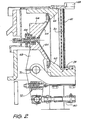
- Fig. 2 illustrates the new pulsing hutch assembly in more detail.
- the inner surfaces of the hutch chamber walls are convergent in the direction of travel of a particle - i.e. radially outwards for a centrifugal jig as illustrated, or downwards for a non-rotary jig (not shown) - for example conical or rectangular pyramidal, with the concentrate outlet spigot 44 at its apex.
- the radially inwards portion 62 of the hutch is part of the casting of the jig screen housing 28, while the radially outwards part surrounding and attached to the outlet spigot 44 is formed by a diaphragm 64 backed by a support block 66.
- Each support block is attached to the upper end of a lever 68 pivoting about a fulcrum member 70 attached to the screen housing 28.
- the lower end of each lever is attached to a respective pushrod 40.
- the heavy block 66 behind the diaphragm causes the hutch to be strongly biased toward the radially outwards (non-pulsing) position under influence of the centrifugal motion of the jig. This causes the hutch to quickly and positively return to this position after actuation of the pushrod by the crank, holding the pushrods 40 against the crank 38 with little or no "bounce".
- This is an advance over the prior art, in which the pulse water pressure was used to force the diaphragm return, and gives protection against damage to the machine in the event of the hutch water supply being interrupted.
- a spring actuated lever return 72 may also be provided to hold the hutch in the non-pulsed position when the jig is stationary or is being rotated at very low speeds for routine maintenance.
- the depth of water through which each pulse is transferred from the pulsator to the ragging is decreased. This allows higher pulsation rates with greater coupling between the pulsator and the ragging, resulting in less water hammer and smoother operation of the jig.
- a yet further advantage is more even dilation of the bed of ragging, allowing more efficient use of the screen area and therefore increasing the throughput capacity of the jig, due to the pulsator.
Landscapes
- Engineering & Computer Science (AREA)
- Mechanical Engineering (AREA)
- Centrifugal Separators (AREA)
- Separation Of Solids By Using Liquids Or Pneumatic Power (AREA)
- Catching Or Destruction (AREA)
- Cleaning In General (AREA)
- Apparatuses For Generation Of Mechanical Vibrations (AREA)
- Combined Means For Separation Of Solids (AREA)
Applications Claiming Priority (3)
| Application Number | Priority Date | Filing Date | Title |
|---|---|---|---|
| AUPO869197 | 1997-08-20 | ||
| AUPO8691A AUPO869197A0 (en) | 1997-08-20 | 1997-08-20 | Hutch chamber for jig |
| PCT/AU1998/000657 WO1999008795A1 (en) | 1997-08-20 | 1998-08-20 | Hutch chamber for jig |
Publications (3)
| Publication Number | Publication Date |
|---|---|
| EP1005396A1 EP1005396A1 (en) | 2000-06-07 |
| EP1005396A4 EP1005396A4 (en) | 2002-04-17 |
| EP1005396B1 true EP1005396B1 (en) | 2005-11-09 |
Family
ID=3802978
Family Applications (1)
| Application Number | Title | Priority Date | Filing Date |
|---|---|---|---|
| EP98938535A Expired - Lifetime EP1005396B1 (en) | 1997-08-20 | 1998-08-20 | Hutch chamber for jig |
Country Status (22)
| Country | Link |
|---|---|
| US (2) | US6286686B1 (pl) |
| EP (1) | EP1005396B1 (pl) |
| JP (1) | JP4591880B2 (pl) |
| CN (1) | CN1191887C (pl) |
| AR (1) | AR015153A1 (pl) |
| AT (1) | ATE309047T1 (pl) |
| AU (1) | AUPO869197A0 (pl) |
| BR (1) | BR9812278A (pl) |
| CA (1) | CA2301925C (pl) |
| CZ (1) | CZ295192B6 (pl) |
| DE (1) | DE69832285T2 (pl) |
| EA (1) | EA001242B1 (pl) |
| ES (1) | ES2256951T3 (pl) |
| ID (1) | ID24286A (pl) |
| IL (1) | IL134475A (pl) |
| MX (1) | MXPA00001708A (pl) |
| NO (1) | NO20000770L (pl) |
| NZ (1) | NZ502899A (pl) |
| PL (1) | PL192960B1 (pl) |
| TR (1) | TR200000464T2 (pl) |
| WO (1) | WO1999008795A1 (pl) |
| ZA (1) | ZA987541B (pl) |
Families Citing this family (9)
| Publication number | Priority date | Publication date | Assignee | Title |
|---|---|---|---|---|
| AUPO869197A0 (en) * | 1997-08-20 | 1997-09-11 | Lowan (Management) Pty Limited | Hutch chamber for jig |
| AUPR437601A0 (en) * | 2001-04-12 | 2001-05-17 | Wmc Resources Limited | Process for sulphide concentration |
| EP1767273A1 (fr) * | 2005-09-27 | 2007-03-28 | Genimin | Procédé et appareil pour la concentration de matières à l'état de particules solides |
| CN102189036B (zh) * | 2010-03-15 | 2013-10-16 | 钦州鑫能源科技有限公司 | 离心跳汰机 |
| WO2016168325A1 (en) | 2015-04-13 | 2016-10-20 | Virginia Tech Intellectual Properties, Inc. | Apparatus for dewatering and demineralization of fine particles |
| WO2016176713A1 (en) * | 2015-05-05 | 2016-11-10 | Gekko Systems Pty Ltd | A ragging bed with barrier for use in a separation apparatus |
| WO2016176714A1 (en) * | 2015-05-05 | 2016-11-10 | Gekko Systems Pty Ltd | Separation apparatus with multiple separation zones |
| US10159988B1 (en) * | 2018-01-24 | 2018-12-25 | James Ray Nelson | Gold and gemstone wet or dry recovery method and machine |
| CN110935553B (zh) * | 2019-11-29 | 2025-07-08 | 云南焠金时代科技有限公司 | 一种圆环形盘式选矿机及选矿方法 |
Family Cites Families (15)
| Publication number | Priority date | Publication date | Assignee | Title |
|---|---|---|---|---|
| US1141419A (en) * | 1914-06-18 | 1915-06-01 | Karl Senn | Combined batea, jig, and pan motion concentrator. |
| US2129795A (en) * | 1936-09-18 | 1938-09-13 | Placer Dev Ltd | Ore jig |
| JPS533902U (pl) * | 1976-06-28 | 1978-01-14 | ||
| US4279741A (en) * | 1979-05-07 | 1981-07-21 | Intercontinental Development Corporation | Method and apparatus for centrifugally separating a heavy fraction from a light weight fraction within a pulp material |
| US4574046A (en) * | 1984-09-21 | 1986-03-04 | Sprow Earnest A | Centrifugal jig for ore beneficiation |
| JPH0248043Y2 (pl) * | 1984-12-14 | 1990-12-17 | ||
| AR240262A1 (es) | 1985-01-25 | 1990-03-30 | Lowan Management Pty | Criba hidraulica centrifuga. |
| JPH0415307Y2 (pl) * | 1987-06-12 | 1992-04-07 | ||
| IN174814B (pl) * | 1988-07-01 | 1995-03-18 | Lowan Man Pty Ltd | |
| JPH037944U (pl) * | 1989-06-08 | 1991-01-25 | ||
| US4998986A (en) * | 1990-01-25 | 1991-03-12 | Trans Mar, Inc. | Centrifugal jig pulsing system |
| RU2077388C1 (ru) * | 1994-03-14 | 1997-04-20 | Товарищество с ограниченной ответственностью "Совместное советско-британское предприятие "Урал" | Отсадочная машина |
| US5938043A (en) * | 1997-05-23 | 1999-08-17 | Fine Gold Recovery Systems, Inc. | Centrifugal jig |
| AUPO869197A0 (en) * | 1997-08-20 | 1997-09-11 | Lowan (Management) Pty Limited | Hutch chamber for jig |
| US6244446B1 (en) * | 1999-10-08 | 2001-06-12 | Richard L. Schmittel | Method and apparatus for continuously separating a more dense fraction from a less dense fraction of a pulp material |
-
1997
- 1997-08-20 AU AUPO8691A patent/AUPO869197A0/en not_active Abandoned
-
1998
- 1998-08-20 ZA ZA987541A patent/ZA987541B/xx unknown
- 1998-08-20 DE DE69832285T patent/DE69832285T2/de not_active Expired - Lifetime
- 1998-08-20 EA EA200000238A patent/EA001242B1/ru not_active IP Right Cessation
- 1998-08-20 WO PCT/AU1998/000657 patent/WO1999008795A1/en not_active Ceased
- 1998-08-20 PL PL338709A patent/PL192960B1/pl not_active IP Right Cessation
- 1998-08-20 EP EP98938535A patent/EP1005396B1/en not_active Expired - Lifetime
- 1998-08-20 IL IL13447598A patent/IL134475A/xx not_active IP Right Cessation
- 1998-08-20 ID IDW20000538D patent/ID24286A/id unknown
- 1998-08-20 CN CNB988082683A patent/CN1191887C/zh not_active Expired - Fee Related
- 1998-08-20 JP JP2000509523A patent/JP4591880B2/ja not_active Expired - Fee Related
- 1998-08-20 US US09/486,081 patent/US6286686B1/en not_active Expired - Lifetime
- 1998-08-20 MX MXPA00001708A patent/MXPA00001708A/es active IP Right Grant
- 1998-08-20 ES ES98938535T patent/ES2256951T3/es not_active Expired - Lifetime
- 1998-08-20 AT AT98938535T patent/ATE309047T1/de not_active IP Right Cessation
- 1998-08-20 BR BR9812278-9A patent/BR9812278A/pt not_active IP Right Cessation
- 1998-08-20 CA CA002301925A patent/CA2301925C/en not_active Expired - Fee Related
- 1998-08-20 TR TR2000/00464T patent/TR200000464T2/xx unknown
- 1998-08-20 CZ CZ2000534A patent/CZ295192B6/cs not_active IP Right Cessation
- 1998-08-20 AR ARP980104111A patent/AR015153A1/es active IP Right Grant
- 1998-08-20 NZ NZ502899A patent/NZ502899A/en unknown
-
2000
- 2000-02-16 NO NO20000770A patent/NO20000770L/no not_active Application Discontinuation
-
2001
- 2001-08-27 US US09/938,593 patent/US6612443B2/en not_active Expired - Fee Related
Also Published As
| Publication number | Publication date |
|---|---|
| EA200000238A1 (ru) | 2000-08-28 |
| EP1005396A1 (en) | 2000-06-07 |
| JP4591880B2 (ja) | 2010-12-01 |
| ATE309047T1 (de) | 2005-11-15 |
| BR9812278A (pt) | 2000-07-18 |
| CN1191887C (zh) | 2005-03-09 |
| CA2301925A1 (en) | 1999-02-25 |
| AUPO869197A0 (en) | 1997-09-11 |
| DE69832285T2 (de) | 2006-08-03 |
| AR015153A1 (es) | 2001-04-18 |
| CN1267240A (zh) | 2000-09-20 |
| PL192960B1 (pl) | 2006-12-29 |
| JP2001514963A (ja) | 2001-09-18 |
| EP1005396A4 (en) | 2002-04-17 |
| ZA987541B (en) | 1999-02-23 |
| NZ502899A (en) | 2001-10-26 |
| TR200000464T2 (tr) | 2001-07-23 |
| NO20000770D0 (no) | 2000-02-16 |
| US6612443B2 (en) | 2003-09-02 |
| WO1999008795A1 (en) | 1999-02-25 |
| DE69832285D1 (de) | 2005-12-15 |
| MXPA00001708A (es) | 2005-02-17 |
| CZ2000534A3 (cs) | 2000-09-13 |
| ES2256951T3 (es) | 2006-07-16 |
| CZ295192B6 (cs) | 2005-06-15 |
| US20010054575A1 (en) | 2001-12-27 |
| US6286686B1 (en) | 2001-09-11 |
| IL134475A0 (en) | 2001-04-30 |
| CA2301925C (en) | 2009-08-04 |
| IL134475A (en) | 2003-11-23 |
| NO20000770L (no) | 2000-02-16 |
| PL338709A1 (en) | 2000-11-20 |
| ID24286A (id) | 2000-07-13 |
| EA001242B1 (ru) | 2000-12-25 |
Similar Documents
| Publication | Publication Date | Title |
|---|---|---|
| EP1005396B1 (en) | Hutch chamber for jig | |
| AU544495B2 (en) | Method and apparatus for centrifugal stratification | |
| US4056464A (en) | Mineral jigs | |
| EP0211869B1 (en) | Centrifugal jig | |
| AU724263B2 (en) | Hutch chamber for jig | |
| US5114569A (en) | Jig pulsion mechanism | |
| CN215140729U (zh) | 一种高效分离的有机质分离装置及有机质分离系统 | |
| JPH06505670A (ja) | 懸濁液から比較的粗い粒子を連続的に分離する方法及び装置 | |
| CN117225534B (zh) | 一种高效破碎的反击锤式破碎机 | |
| US6079567A (en) | Separator for separating particles from a slurry | |
| AU618832B2 (en) | Jig pulsion mechanism | |
| AU573960B2 (en) | Centrifugal jig | |
| CN86107473A (zh) | 砂金分离装置 | |
| US633686A (en) | Ore-concentrator. | |
| US1029089A (en) | Ore-concentrating launder. | |
| AU684153B2 (en) | Separator for separating particles from a slurry |
Legal Events
| Date | Code | Title | Description |
|---|---|---|---|
| PUAI | Public reference made under article 153(3) epc to a published international application that has entered the european phase |
Free format text: ORIGINAL CODE: 0009012 |
|
| 17P | Request for examination filed |
Effective date: 20000225 |
|
| AK | Designated contracting states |
Kind code of ref document: A1 Designated state(s): AT BE CH CY DE DK ES FI FR GB GR IE IT LI LU MC NL PT SE |
|
| A4 | Supplementary search report drawn up and despatched |
Effective date: 20020301 |
|
| AK | Designated contracting states |
Kind code of ref document: A4 Designated state(s): AT BE CH CY DE DK ES FI FR GB GR IE IT LI LU MC NL PT SE |
|
| 17Q | First examination report despatched |
Effective date: 20031209 |
|
| GRAP | Despatch of communication of intention to grant a patent |
Free format text: ORIGINAL CODE: EPIDOSNIGR1 |
|
| GRAS | Grant fee paid |
Free format text: ORIGINAL CODE: EPIDOSNIGR3 |
|
| GRAA | (expected) grant |
Free format text: ORIGINAL CODE: 0009210 |
|
| AK | Designated contracting states |
Kind code of ref document: B1 Designated state(s): AT BE CH CY DE DK ES FI FR GB GR IE IT LI LU MC NL PT SE |
|
| PG25 | Lapsed in a contracting state [announced via postgrant information from national office to epo] |
Ref country code: LI Free format text: LAPSE BECAUSE OF FAILURE TO SUBMIT A TRANSLATION OF THE DESCRIPTION OR TO PAY THE FEE WITHIN THE PRESCRIBED TIME-LIMIT Effective date: 20051109 Ref country code: FI Free format text: LAPSE BECAUSE OF FAILURE TO SUBMIT A TRANSLATION OF THE DESCRIPTION OR TO PAY THE FEE WITHIN THE PRESCRIBED TIME-LIMIT Effective date: 20051109 Ref country code: CH Free format text: LAPSE BECAUSE OF FAILURE TO SUBMIT A TRANSLATION OF THE DESCRIPTION OR TO PAY THE FEE WITHIN THE PRESCRIBED TIME-LIMIT Effective date: 20051109 Ref country code: BE Free format text: LAPSE BECAUSE OF FAILURE TO SUBMIT A TRANSLATION OF THE DESCRIPTION OR TO PAY THE FEE WITHIN THE PRESCRIBED TIME-LIMIT Effective date: 20051109 Ref country code: AT Free format text: LAPSE BECAUSE OF FAILURE TO SUBMIT A TRANSLATION OF THE DESCRIPTION OR TO PAY THE FEE WITHIN THE PRESCRIBED TIME-LIMIT Effective date: 20051109 |
|
| REG | Reference to a national code |
Ref country code: GB Ref legal event code: FG4D |
|
| REG | Reference to a national code |
Ref country code: CH Ref legal event code: EP |
|
| REG | Reference to a national code |
Ref country code: IE Ref legal event code: FG4D |
|
| REF | Corresponds to: |
Ref document number: 69832285 Country of ref document: DE Date of ref document: 20051215 Kind code of ref document: P |
|
| RAP2 | Party data changed (patent owner data changed or rights of a patent transferred) |
Owner name: EDI RAIL PTY LTD |
|
| PG25 | Lapsed in a contracting state [announced via postgrant information from national office to epo] |
Ref country code: GR Free format text: LAPSE BECAUSE OF FAILURE TO SUBMIT A TRANSLATION OF THE DESCRIPTION OR TO PAY THE FEE WITHIN THE PRESCRIBED TIME-LIMIT Effective date: 20060209 Ref country code: DK Free format text: LAPSE BECAUSE OF FAILURE TO SUBMIT A TRANSLATION OF THE DESCRIPTION OR TO PAY THE FEE WITHIN THE PRESCRIBED TIME-LIMIT Effective date: 20060209 |
|
| NLT2 | Nl: modifications (of names), taken from the european patent patent bulletin |
Owner name: EDI RAIL PTY LTD Effective date: 20060104 |
|
| REG | Reference to a national code |
Ref country code: SE Ref legal event code: TRGR |
|
| REG | Reference to a national code |
Ref country code: CH Ref legal event code: PL |
|
| REG | Reference to a national code |
Ref country code: ES Ref legal event code: FG2A Ref document number: 2256951 Country of ref document: ES Kind code of ref document: T3 |
|
| ET | Fr: translation filed | ||
| PG25 | Lapsed in a contracting state [announced via postgrant information from national office to epo] |
Ref country code: IE Free format text: LAPSE BECAUSE OF NON-PAYMENT OF DUE FEES Effective date: 20060821 |
|
| PG25 | Lapsed in a contracting state [announced via postgrant information from national office to epo] |
Ref country code: MC Free format text: LAPSE BECAUSE OF NON-PAYMENT OF DUE FEES Effective date: 20060831 |
|
| PLBE | No opposition filed within time limit |
Free format text: ORIGINAL CODE: 0009261 |
|
| STAA | Information on the status of an ep patent application or granted ep patent |
Free format text: STATUS: NO OPPOSITION FILED WITHIN TIME LIMIT |
|
| 26N | No opposition filed |
Effective date: 20060810 |
|
| REG | Reference to a national code |
Ref country code: IE Ref legal event code: MM4A |
|
| PG25 | Lapsed in a contracting state [announced via postgrant information from national office to epo] |
Ref country code: LU Free format text: LAPSE BECAUSE OF NON-PAYMENT OF DUE FEES Effective date: 20060820 |
|
| PG25 | Lapsed in a contracting state [announced via postgrant information from national office to epo] |
Ref country code: CY Free format text: LAPSE BECAUSE OF FAILURE TO SUBMIT A TRANSLATION OF THE DESCRIPTION OR TO PAY THE FEE WITHIN THE PRESCRIBED TIME-LIMIT Effective date: 20051109 |
|
| PGFP | Annual fee paid to national office [announced via postgrant information from national office to epo] |
Ref country code: ES Payment date: 20090706 Year of fee payment: 12 |
|
| PGFP | Annual fee paid to national office [announced via postgrant information from national office to epo] |
Ref country code: SE Payment date: 20090826 Year of fee payment: 12 Ref country code: PT Payment date: 20090702 Year of fee payment: 12 Ref country code: NL Payment date: 20090818 Year of fee payment: 12 Ref country code: GB Payment date: 20090714 Year of fee payment: 12 |
|
| PGFP | Annual fee paid to national office [announced via postgrant information from national office to epo] |
Ref country code: DE Payment date: 20091030 Year of fee payment: 12 |
|
| PGFP | Annual fee paid to national office [announced via postgrant information from national office to epo] |
Ref country code: IT Payment date: 20090724 Year of fee payment: 12 |
|
| REG | Reference to a national code |
Ref country code: PT Ref legal event code: MM4A Free format text: LAPSE DUE TO NON-PAYMENT OF FEES Effective date: 20110221 |
|
| REG | Reference to a national code |
Ref country code: NL Ref legal event code: V1 Effective date: 20110301 |
|
| EUG | Se: european patent has lapsed | ||
| GBPC | Gb: european patent ceased through non-payment of renewal fee |
Effective date: 20100820 |
|
| PG25 | Lapsed in a contracting state [announced via postgrant information from national office to epo] |
Ref country code: PT Free format text: LAPSE BECAUSE OF NON-PAYMENT OF DUE FEES Effective date: 20110221 Ref country code: NL Free format text: LAPSE BECAUSE OF NON-PAYMENT OF DUE FEES Effective date: 20110301 Ref country code: IT Free format text: LAPSE BECAUSE OF NON-PAYMENT OF DUE FEES Effective date: 20100820 |
|
| REG | Reference to a national code |
Ref country code: DE Ref legal event code: R119 Ref document number: 69832285 Country of ref document: DE Effective date: 20110301 |
|
| PG25 | Lapsed in a contracting state [announced via postgrant information from national office to epo] |
Ref country code: DE Free format text: LAPSE BECAUSE OF NON-PAYMENT OF DUE FEES Effective date: 20110301 |
|
| PG25 | Lapsed in a contracting state [announced via postgrant information from national office to epo] |
Ref country code: GB Free format text: LAPSE BECAUSE OF NON-PAYMENT OF DUE FEES Effective date: 20100820 |
|
| REG | Reference to a national code |
Ref country code: ES Ref legal event code: FD2A Effective date: 20111019 |
|
| PG25 | Lapsed in a contracting state [announced via postgrant information from national office to epo] |
Ref country code: ES Free format text: LAPSE BECAUSE OF NON-PAYMENT OF DUE FEES Effective date: 20100821 |
|
| PGFP | Annual fee paid to national office [announced via postgrant information from national office to epo] |
Ref country code: FR Payment date: 20110901 Year of fee payment: 14 |
|
| PG25 | Lapsed in a contracting state [announced via postgrant information from national office to epo] |
Ref country code: SE Free format text: LAPSE BECAUSE OF NON-PAYMENT OF DUE FEES Effective date: 20100821 |
|
| REG | Reference to a national code |
Ref country code: FR Ref legal event code: ST Effective date: 20130430 |
|
| PG25 | Lapsed in a contracting state [announced via postgrant information from national office to epo] |
Ref country code: FR Free format text: LAPSE BECAUSE OF NON-PAYMENT OF DUE FEES Effective date: 20120831 |