EP1005251B1 - Method of producing speaker diaphragm and speaker diaphragm formed by this method and speaker using this - Google Patents
Method of producing speaker diaphragm and speaker diaphragm formed by this method and speaker using this Download PDFInfo
- Publication number
- EP1005251B1 EP1005251B1 EP99924013A EP99924013A EP1005251B1 EP 1005251 B1 EP1005251 B1 EP 1005251B1 EP 99924013 A EP99924013 A EP 99924013A EP 99924013 A EP99924013 A EP 99924013A EP 1005251 B1 EP1005251 B1 EP 1005251B1
- Authority
- EP
- European Patent Office
- Prior art keywords
- diaphragm
- loudspeaker
- loudspeaker diaphragm
- reactive chamber
- manufacturing
- Prior art date
- Legal status (The legal status is an assumption and is not a legal conclusion. Google has not performed a legal analysis and makes no representation as to the accuracy of the status listed.)
- Expired - Lifetime
Links
Images


Classifications
-
- H—ELECTRICITY
- H04—ELECTRIC COMMUNICATION TECHNIQUE
- H04R—LOUDSPEAKERS, MICROPHONES, GRAMOPHONE PICK-UPS OR LIKE ACOUSTIC ELECTROMECHANICAL TRANSDUCERS; DEAF-AID SETS; PUBLIC ADDRESS SYSTEMS
- H04R31/00—Apparatus or processes specially adapted for the manufacture of transducers or diaphragms therefor
- H04R31/003—Apparatus or processes specially adapted for the manufacture of transducers or diaphragms therefor for diaphragms or their outer suspension
Definitions
- the present invention relates to the field of methods for manufacturing loudspeaker diaphragms employed in a range of audio equipment, loudspeaker diaphragms made using such methods, and loudspeakers employing such diaphragms.
- a magnetic circuit 15 includes a magnet 15a, lower plate 15b, and upper plate 15c.
- a frame 16 is bonded to the magnetic circuit 15.
- a damper 17 holds a voice coil 18. The outer circumference of the damper 17 is bonded to the frame 16, and its inner circumference is bonded to the voice coil 18 whose coil 18a is embedded in the magnetic gap 15d of the magnetic circuit 15.
- a loudspeaker diaphragm 19 is bonded to the frame 16 via an edge 19a bonded to its outer circumference, and the inner circumference of the loudspeaker diaphragm 19 is bonded to the voice coil 18.
- This loudspeaker diaphragm 19 is generally made mainly of paper or thin resin plates, which is selected depending on the need for weather resistance and required acoustic characteristics.
- a loudspeaker diaphragm made of polyethylene which is a type of polyolefin system, has low material density which gives the loudspeaker diaphragm a low mass. It also has relatively large internal loss with respect to mechanical vibration, which improves the frequency characteristic of the loudspeaker. Accordingly, polyethylene loudspeaker diaphragms are commonly used in loudspeakers. However, a polyethylene loudspeaker diaphragm has low adhesivity, making it essential to activate the surface of the loudspeaker diaphragm to improve bonding strength.
- Common conventional methods for activating the surface of the loudspeaker diaphragm 19 include the application of primer after corona discharge, and surface treatment of the loudspeaker diaphragm 19 by the gas plasma treatment method using parallel flat electrodes 20 and 21 as shown in Figs. 8 and 9 .
- the conventional surface activating technology for treating the surface of the loudspeaker diaphragm has the following disadvantages.
- a large processing apparatus is required because only the areas close to electrodes 20 and 21 are activated if the electrodes are small, causing a deviation in wettability of the loudspeaker diaphragm 19.
- this treatment takes about 30 seconds for one face of the loudspeaker diaphragm 19.
- the workpiece then needs to be flipped or the loudspeaker diaphragm 19 needs to be flipped to apply treatment to the other face, requiring more than one minute for each piece and seriously degrading productivity.
- the loudspeaker diaphragm may deform during corona discharge due to high temperatures above 80 °C in the reactive chamber.
- the method using the parallel flat electrode 20 in Fig. 8 also creates the risk of heat deformation and low productivity of the loudspeaker diaphragm 19.
- the method using the parallel flat electrode 21 in Fig. 9 may also cause low productivity. If more than one loudspeaker diaphragm 19 is handled at once to solve the problem of low productivity, it may still have the risk of heat deformation, and significant difference in wettability between the periphery and the center.
- Document JP 60 048696 A discloses a method for manufacturing a diaphragm for a speaker.
- a base for the diaphragm made of polyolefin resin or its copolymer is formed in the shape of the diaphragm, and then the surface is activated by irradiating an inorganic gaseous plasma, such as gaseous oxygen or gaseous nitrogen, onto the surface.
- an inorganic gaseous plasma such as gaseous oxygen or gaseous nitrogen
- Document JP 06 272035 A shows a plasma treating device comprising a cylindrical chamber, an outside electrode that is connected to a high frequency oscillator, and an inside electrode that is electrically insulated from the outside electrode.
- the outside electrode is arranged at the outside of the cylindrical chamber, and the inside electrode is coaxially arranged at the inside of the cylindrical chamber.
- the inside electrode has a cooling medium for cooling itself.
- a resin loudspeaker diaphragm made by injection molding or sheet forming by heating is disposed in a reactive chamber, and electrodes are provided outside of the reactive chamber. Plasma is applied to the loudspeaker diaphragm to activate the surface. Provision of electrodes outside the reactive chamber enables to keep the temperature of the reactive chamber below the heat deformation temperature of the loudspeaker diaphragm during plasma treatment. Accordingly, heat deformation of the loudspeaker diaphragm is preventable and defects caused by heat deformation can be suppressed.
- a method for manufacturing a loudspeaker diaphragm in an exemplary embodiment of the present invention is described with reference to Figs. 1 to 6 .
- the configuration of the loudspeaker itself is the same as that of the prior art, and thus its explanation is omitted here.
- a meshed cylindrical aluminum etching tunnel 2 is provided inside a cylindrical quartz reactive chamber 1.
- a loudspeaker diaphragm 4 (corresponding to the loudspeaker diaphragm 19 in the prior art) is held by a loudspeaker diaphragm holder 3 in the reactive chamber 1 in parallel with other loudspeaker diaphragms at approximately equal intervals.
- a gas inlet 6 is provided on the reactive chamber 1, and reactive gas A flows in from this gas inlet 6 through the etching tunnel 2 formed of meshed aluminum to the reactive chamber 1.
- Two pairs of electrodes 5 are provided facing each other on the outside face of the reactive chamber 1.
- a gas outlet 7 is also provided.
- Ultra high polymer polyethylene resin called “LUBMER” (product name) manufactured by Mitsui Chemicals, Inc. is used for the loudspeaker diaphragm 4.
- This "LUBMER” is formed into the loudspeaker diaphragm 4 having a diameter of 16 cm by composite molding of injection or pressing, using an ultra high speed injection molding machine.
- the characteristics of this resin are shown in Table 1.
- Table 1 Heat deformation temperature 82 °C Melting point 137 °C Water absorption rate 0.01 > % Strength of tensile breakage point 530 kg/cm 2 Elongation of breakage point 7 % Bending strength 18400 kg/cm 2
- the size of the quartz reactive chamber 1 is 300 mm in diameter and 500 mm in length. As shown in Fig. 2 , 30 loudspeaker diaphragms 4 of diameter 16 cm are aligned at 15 mm intervals.
- oxygen gas is employed for the reactive gas A.
- Fig. 3 shows the changes in temperature during consecutive operations under the above conditions. As shown in Fig. 3 , the temperature inside the reactive chamber is stabilized at about 45 °C even after consecutive operation for 12 hours, and no loudspeaker diaphragm 4 was deformed.
- the wettability of the loudspeaker diaphragm 4 obtained through the above process is 50 dyn/cm or above on any part of the loudspeaker diaphragm 4. This allows the assumption that plasma is applied uniformly by the use of the meshed etching tunnel 2.
- isocyanate manufactured by Takeda Chemical Industries. Ltd. called “Takenate M402" (product name) is used as the primer.
- Fig. 4 shows the durability of its wettability.
- the exemplary embodiment in which the primer is applied after plasma treatment is shown as characteristic C in Fig. 4 . It shows that the wettability immediately after treatment is a very high 50 dyn/cm, and the primer maintains a high wettability of 44 dyn/cm for considerable time, proving its stability.
- the strength was compared between the loudspeaker diaphragm 4 to which the primer was applied after plasma treatment in this exemplary embodiment and the voice coil 18 and edge 19a were bonded using adhesives 12 and 13; and the conventional loudspeaker diaphragm to which the primer was applied after corona discharge and the voice coil and edge were bonded.
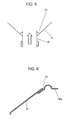
- the voice coil 18 shown in Fig. 5 has a diameter of 32 mm.
- the adhesive 13 is a two-part reactive acrylic adhesive, and it is used for bonding the voice coil 18 onto the loudspeaker diaphragm 4. The bonding strength was measured by pulling the voice coil 18 in the direction indicated by the arrow.
- the edge 19a shown in Fig. 6 is made of rubber, and it is bonded to the loudspeaker diaphragm 4 using the adhesive 12 which is butyl rubber solvent adhesive.
- the peeling strength was tested using a bonding area of 25 mm wide and 5 mm long.
- the bonded area has peeled off in the conventional loudspeaker using corona discharge by input of 70 W.
- burning of the voice coil 18 occurred by input of 120 W.
- no peeling of the bonded area has occurred, demonstrating extremely high bonding strength.
- the reactive gas A approximately the same results as for oxygen were obtained by the use of nitrogen gas or air.
- the material of the loudspeaker diaphragm 4 approximately the same effect was obtained with polypropylene or nylon resin.
- the exemplary embodiment provides electrodes 5 outside the reactive chamber 1 for plasma treatment. This enables the suppression of temperature rise in the reactive chamber 1 and prevents heat deformation of the loudspeaker diaphragm 4.
- plasma can be uniformly applied by placing the loudspeaker diaphragm 4 in a meshed metal frame, resulting in improved productivity.
- the method for manufacturing a loudspeaker diaphragm of the present invention disposes a resin loudspeaker diaphragm made by injection molding or sheet forming by heating in the reactive chamber, and provides electrodes outside the reactive chamber. This enables the temperature inside the reactive chamber to be kept below the heat deformation temperature of the loudspeaker diaphragm during surface activation of the loudspeaker diaphragm by application of plasma. The temperature inside the reactive chamber is kept below the heat deformation temperature of the loudspeaker diaphragm to prevent heat deformation of the loudspeaker diaphragm and to suppress the occurrence of defects caused by heat deformation.
- more than one loudspeaker diaphragm is disposed inside the meshed metal frame in the reactive chamber at a predetermined interval to apply plasma almost uniformly.
- the gas disperses almost uniformly inside the reactive chamber through the meshed metal frame so that the surface is almost uniformly activated, assuring high wettability and stable high quality of the loudspeaker diaphragm.
- the material used for the loudspeaker diaphragm of the present invention is a monopolymer or copolymer of polyolefin resin such as polyethylene and polypropylene, or monopolymer or copolymer of polyamide resin. This enables a broad range of loudspeaker diaphragms with improved bonding strength and stable quality to be manufactured.
- a loudspeaker manufactured using the loudspeaker diaphragm manufactured as above thus has uniform and improved bonding strength between the loudspeaker diaphragm and edge and/or voice coils, offering loudspeakers with improved input power durability.
Description
- The present invention relates to the field of methods for manufacturing loudspeaker diaphragms employed in a range of audio equipment, loudspeaker diaphragms made using such methods, and loudspeakers employing such diaphragms.
- The configuration of a conventional loudspeaker is described with reference to its sectional view in
Fig. 7 . Amagnetic circuit 15 includes amagnet 15a,lower plate 15b, andupper plate 15c. - A
frame 16 is bonded to themagnetic circuit 15. Adamper 17 holds avoice coil 18. The outer circumference of thedamper 17 is bonded to theframe 16, and its inner circumference is bonded to thevoice coil 18 whosecoil 18a is embedded in themagnetic gap 15d of themagnetic circuit 15. - A
loudspeaker diaphragm 19 is bonded to theframe 16 via anedge 19a bonded to its outer circumference, and the inner circumference of theloudspeaker diaphragm 19 is bonded to thevoice coil 18. Thisloudspeaker diaphragm 19 is generally made mainly of paper or thin resin plates, which is selected depending on the need for weather resistance and required acoustic characteristics. - A method for manufacturing a
typical loudspeaker diaphragm 19 made of resin, more specifically a polyolefin polyethylene loudspeaker diaphragm, is described next. - A loudspeaker diaphragm made of polyethylene, which is a type of polyolefin system, has low material density which gives the loudspeaker diaphragm a low mass. It also has relatively large internal loss with respect to mechanical vibration, which improves the frequency characteristic of the loudspeaker. Accordingly, polyethylene loudspeaker diaphragms are commonly used in loudspeakers. However, a polyethylene loudspeaker diaphragm has low adhesivity, making it essential to activate the surface of the loudspeaker diaphragm to improve bonding strength.
- Common conventional methods for activating the surface of the
loudspeaker diaphragm 19 include the application of primer after corona discharge, and surface treatment of theloudspeaker diaphragm 19 by the gas plasma treatment method using parallelflat electrodes Figs. 8 and9 . - However, the conventional surface activating technology for treating the surface of the loudspeaker diaphragm has the following disadvantages.
- As for the method involving surface activation by corona discharge and primer application, a large processing apparatus is required because only the areas close to
electrodes loudspeaker diaphragm 19. In addition, this treatment takes about 30 seconds for one face of theloudspeaker diaphragm 19. The workpiece then needs to be flipped or theloudspeaker diaphragm 19 needs to be flipped to apply treatment to the other face, requiring more than one minute for each piece and seriously degrading productivity. - Furthermore, it has another problem that the loudspeaker diaphragm may deform during corona discharge due to high temperatures above 80 °C in the reactive chamber.
- The method using the parallel
flat electrode 20 inFig. 8 also creates the risk of heat deformation and low productivity of theloudspeaker diaphragm 19. The method using the parallelflat electrode 21 inFig. 9 may also cause low productivity. If more than oneloudspeaker diaphragm 19 is handled at once to solve the problem of low productivity, it may still have the risk of heat deformation, and significant difference in wettability between the periphery and the center. - Document
JP 60 048696 A - Document
JP 06 272035 A - Document
US 5 352 902 describes a reaction vessel having a pair of electrodes outside the reaction vessel for plasma-processing semiconductor wafers. One of the electrodes is connected to a high-frequency power source, and the other electrode is grounded. - It is an aim of the present invention to provide for a method of manufacturing a loudspeaker diaphragm which prevents heat deformation of the loudspeaker diaphragm and which suppresses the occurrence of defects caused by heat deformation.
- This is achieved by the features as set forth in
claim 1. Further advantageous embodiments of the present invention are set forth in the dependent claims. - A resin loudspeaker diaphragm made by injection molding or sheet forming by heating is disposed in a reactive chamber, and electrodes are provided outside of the reactive chamber. Plasma is applied to the loudspeaker diaphragm to activate the surface. Provision of electrodes outside the reactive chamber enables to keep the temperature of the reactive chamber below the heat deformation temperature of the loudspeaker diaphragm during plasma treatment. Accordingly, heat deformation of the loudspeaker diaphragm is preventable and defects caused by heat deformation can be suppressed.
-
-
Fig. 1 is a perspective view illustrating a method for manufacturing a loudspeaker diaphragm in an exemplary embodiment of the present invention for describing plasma treatment of the loudspeaker diaphragm. -
Fig. 2 is a sectional view illustrating the loudspeaker diaphragm aligned in a quartz reactive chamber, which is a part of the exemplary embodiment of the present invention. -
Fig. 3 is a temperature change graph during consecutive operation of the quartz reactive chamber in the exemplary embodiment of the present invention. -
Fig. 4 is a comparison of durability of wettability in the exemplary embodiment of the present invention. -
Fig. 5 is a sectional view illustrating the bonding state of the loudspeaker diaphragm and a voice coil. -
Fig. 6 is a sectional view illustrating the bonding state of the loudspeaker diaphragm and an edge. -
Fig. 7 is a side sectional view of a conventional loudspeaker. -
Fig. 8 is a sectional view of a portion of a conventional loudspeaker illustrating plasma treatment for the loudspeaker diaphragm using parallel flat electrodes. -
Fig. 9 is a sectional view of a portion of a conventional loudspeaker illustrating plasma treatment for the loudspeaker diaphragm inFig. 8 using another type of parallel flat electrodes. - A method for manufacturing a loudspeaker diaphragm in an exemplary embodiment of the present invention is described with reference to
Figs. 1 to 6 . The configuration of the loudspeaker itself is the same as that of the prior art, and thus its explanation is omitted here. - In
Figs. 1 to 6 , a meshed cylindricalaluminum etching tunnel 2 is provided inside a cylindrical quartzreactive chamber 1. A loudspeaker diaphragm 4 (corresponding to theloudspeaker diaphragm 19 in the prior art) is held by aloudspeaker diaphragm holder 3 in thereactive chamber 1 in parallel with other loudspeaker diaphragms at approximately equal intervals. Agas inlet 6 is provided on thereactive chamber 1, and reactive gas A flows in from thisgas inlet 6 through theetching tunnel 2 formed of meshed aluminum to thereactive chamber 1. Two pairs ofelectrodes 5 are provided facing each other on the outside face of thereactive chamber 1. Agas outlet 7 is also provided. - Details of the method for manufacturing the
loudspeaker diaphragm 4 using the abovereactive chamber 1 are described next. Ultra high polymer polyethylene resin called "LUBMER" (product name) manufactured by Mitsui Chemicals, Inc. is used for theloudspeaker diaphragm 4. This "LUBMER" is formed into theloudspeaker diaphragm 4 having a diameter of 16 cm by composite molding of injection or pressing, using an ultra high speed injection molding machine. The characteristics of this resin are shown in Table 1.Table 1 Heat deformation temperature 82 °C Melting point 137 °C Water absorption rate 0.01 > % Strength of tensile breakage point 530 kg/cm2 Elongation of breakage point 7 % Bending strength 18400 kg/cm2 - It is apparent from Table 1 that this resin starts to deform at 82 °C, and the
loudspeaker diaphragm 4 is exposed to the danger of deformation at the temperature 80°C or above in thereactive chamber 1. - The size of the quartz
reactive chamber 1 is 300 mm in diameter and 500 mm in length. As shown inFig. 2 , 30loudspeaker diaphragms 4 ofdiameter 16 cm are aligned at 15 mm intervals. For the reactive gas A, oxygen gas is employed. - To achieve a vacuum of 0.9 torr under high frequency output of 500 W, the vacuuming time is set to 1.5 minutes, plasma treatment time to 1 minute, and the return to normal pressure 1.5 minutes, which totals about 4 minutes per cycle.
Fig. 3 shows the changes in temperature during consecutive operations under the above conditions. As shown inFig. 3 , the temperature inside the reactive chamber is stabilized at about 45 °C even after consecutive operation for 12 hours, and noloudspeaker diaphragm 4 was deformed. - The wettability of the
loudspeaker diaphragm 4 obtained through the above process is 50 dyn/cm or above on any part of theloudspeaker diaphragm 4. This allows the assumption that plasma is applied uniformly by the use of the meshedetching tunnel 2. - For further improving the quality, isocyanate manufactured by Takeda Chemical Industries. Ltd., called "Takenate M402" (product name) is used as the primer.
Fig. 4 shows the durability of its wettability. - It is apparent from
Fig. 4 that the wettability B immediately after treatment in the conventional method of applying primer after corona discharge is relatively high at 46 dyn/cm. However, it degrades with time, falling to about 36 dyn/cm after 200 hours. - The exemplary embodiment in which the primer is applied after plasma treatment is shown as characteristic C in
Fig. 4 . It shows that the wettability immediately after treatment is a very high 50 dyn/cm, and the primer maintains a high wettability of 44 dyn/cm for considerable time, proving its stability. - Next, as shown in
Figs. 5 and 6 , the strength was compared between theloudspeaker diaphragm 4 to which the primer was applied after plasma treatment in this exemplary embodiment and thevoice coil 18 andedge 19a were bonded usingadhesives - The
voice coil 18 shown inFig. 5 has a diameter of 32 mm. The adhesive 13 is a two-part reactive acrylic adhesive, and it is used for bonding thevoice coil 18 onto theloudspeaker diaphragm 4. The bonding strength was measured by pulling thevoice coil 18 in the direction indicated by the arrow. - The
edge 19a shown inFig. 6 is made of rubber, and it is bonded to theloudspeaker diaphragm 4 using the adhesive 12 which is butyl rubber solvent adhesive. The peeling strength was tested using a bonding area of 25 mm wide and 5 mm long. - A ∅16 cm loudspeaker was then made using the above 032
voice coil 18 andedge 19a, and the input power durability was tested. Table 2 shows the results of each test.Table 2 plasma treatment corona discharge cone ⇔ voice coil 18 kg 11 kg cone ⇔ edge 4.5 kg 2.5 kg input power durability 120 W 70W (breakage mode) damage to voice coil peeling of bonding - It is apparent from Table 2 that the loudspeaker diaphragm of the exemplary embodiment which uses plasma treatment has better bonding strength than the conventional loudspeaker diaphragm using corona discharge.
- In the input power durability test, the bonded area has peeled off in the conventional loudspeaker using corona discharge by input of 70 W. In the exemplary embodiment using plasma processing, burning of the
voice coil 18 occurred by input of 120 W. However, no peeling of the bonded area has occurred, demonstrating extremely high bonding strength. - As for the reactive gas A, approximately the same results as for oxygen were obtained by the use of nitrogen gas or air. As for the material of the
loudspeaker diaphragm 4, approximately the same effect was obtained with polypropylene or nylon resin. - As described above, the exemplary embodiment provides
electrodes 5 outside thereactive chamber 1 for plasma treatment. This enables the suppression of temperature rise in thereactive chamber 1 and prevents heat deformation of theloudspeaker diaphragm 4. In addition, plasma can be uniformly applied by placing theloudspeaker diaphragm 4 in a meshed metal frame, resulting in improved productivity. - The method for manufacturing a loudspeaker diaphragm of the present invention disposes a resin loudspeaker diaphragm made by injection molding or sheet forming by heating in the reactive chamber, and provides electrodes outside the reactive chamber. This enables the temperature inside the reactive chamber to be kept below the heat deformation temperature of the loudspeaker diaphragm during surface activation of the loudspeaker diaphragm by application of plasma. The temperature inside the reactive chamber is kept below the heat deformation temperature of the loudspeaker diaphragm to prevent heat deformation of the loudspeaker diaphragm and to suppress the occurrence of defects caused by heat deformation.
- In addition, more than one loudspeaker diaphragm is disposed inside the meshed metal frame in the reactive chamber at a predetermined interval to apply plasma almost uniformly. The gas disperses almost uniformly inside the reactive chamber through the meshed metal frame so that the surface is almost uniformly activated, assuring high wettability and stable high quality of the loudspeaker diaphragm.
- Moreover, application of isocyanate primer after plasma treatment further improves the bonding strength and stabilizes the quality.
- The material used for the loudspeaker diaphragm of the present invention is a monopolymer or copolymer of polyolefin resin such as polyethylene and polypropylene, or monopolymer or copolymer of polyamide resin. This enables a broad range of loudspeaker diaphragms with improved bonding strength and stable quality to be manufactured.
- A loudspeaker manufactured using the loudspeaker diaphragm manufactured as above thus has uniform and improved bonding strength between the loudspeaker diaphragm and edge and/or voice coils, offering loudspeakers with improved input power durability.
Claims (6)
- A method for manufacturing a diaphragm for a loudspeaker, comprising the steps of:heating a molded resin diaphragm (4) in a reactive chamber (1) which has electrodes (5) for plasma treatment, andactivating the surface of said diaphragm (4) by applying the plasma,characterized in that
the temperature inside said reactive chamber is kept below a heat deformation temperature of said diaphragm (4) by providing the electrodes (5) for plasma treatment outside of the reactive chamber (1). - The method for manufacturing the diaphragm as defined in claim 1, wherein a plurality of molded resin loudspeaker diaphragms (4) are placed inside said reactive chamber (1) at a certain interval so as to apply plasma substantially uniformly.
- The method for manufacturing the diaphragm as defined in claim 1 or 2, wherein isocyanate primer is applied after plasma treatment.
- The method for manufacturing the diaphragm as defined in any of claims 1 to 3, wherein one of monopolymer and copolymer of polyolefin such as polyethylene and polypropylene is used as a material for said diaphragm.
- The method for manufacturing the diaphragm as defined in any of claims 1 to 4, further comprising the step of manufacturing said molded resin loudspeaker diaphragm (4) by injection molding or sheet forming.
- The method for manufacturing the diaphragm as defined in any of claims 1 to 5, wherein said reactive chamber (1) is disposed with a meshed metal frame (2) inside said reactive chamber.
Applications Claiming Priority (3)
| Application Number | Priority Date | Filing Date | Title |
|---|---|---|---|
| JP10164892A JPH11355895A (en) | 1998-06-12 | 1998-06-12 | Manufacture of diaphragm for loudspeaker |
| JP16489298 | 1998-06-12 | ||
| PCT/JP1999/003140 WO1999065272A1 (en) | 1998-06-12 | 1999-06-11 | Method of producing speaker diaphragm and speaker diaphragm formed by this method and speaker using this |
Publications (3)
| Publication Number | Publication Date |
|---|---|
| EP1005251A1 EP1005251A1 (en) | 2000-05-31 |
| EP1005251A4 EP1005251A4 (en) | 2005-03-02 |
| EP1005251B1 true EP1005251B1 (en) | 2008-08-20 |
Family
ID=15801868
Family Applications (1)
| Application Number | Title | Priority Date | Filing Date |
|---|---|---|---|
| EP99924013A Expired - Lifetime EP1005251B1 (en) | 1998-06-12 | 1999-06-11 | Method of producing speaker diaphragm and speaker diaphragm formed by this method and speaker using this |
Country Status (6)
| Country | Link |
|---|---|
| US (3) | US6627140B1 (en) |
| EP (1) | EP1005251B1 (en) |
| JP (1) | JPH11355895A (en) |
| CN (1) | CN1270582C (en) |
| DE (1) | DE69939361D1 (en) |
| WO (1) | WO1999065272A1 (en) |
Families Citing this family (5)
| Publication number | Priority date | Publication date | Assignee | Title |
|---|---|---|---|---|
| JPH11355895A (en) * | 1998-06-12 | 1999-12-24 | Matsushita Electric Ind Co Ltd | Manufacture of diaphragm for loudspeaker |
| JP2007110209A (en) * | 2005-10-11 | 2007-04-26 | Matsushita Electric Ind Co Ltd | Speaker |
| US8889534B1 (en) * | 2013-05-29 | 2014-11-18 | Tokyo Electron Limited | Solid state source introduction of dopants and additives for a plasma doping process |
| TW201545564A (en) * | 2014-05-16 | 2015-12-01 | B O B Co Ltd | Loudspeaker vibration membrane and electric discharge treatment molding method thereof |
| USD835063S1 (en) * | 2017-04-18 | 2018-12-04 | Weiquan Wu | Bluetooth loudspeaker |
Citations (2)
| Publication number | Priority date | Publication date | Assignee | Title |
|---|---|---|---|---|
| JPH06272035A (en) * | 1993-03-16 | 1994-09-27 | Nippon Steel Corp | Plasma treating device |
| US5352902A (en) * | 1992-07-06 | 1994-10-04 | Tokyo Electron Kabushiki Kaisha | Method for controlling plasma surface-treatments with a plurality of photodetectors and optical filters |
Family Cites Families (9)
| Publication number | Priority date | Publication date | Assignee | Title |
|---|---|---|---|---|
| JPS5634297A (en) * | 1979-08-29 | 1981-04-06 | Kenzo Inoue | Speaker unit |
| JPS6048696A (en) * | 1983-08-26 | 1985-03-16 | Onkyo Corp | Manufacture of diaphragm for speaker |
| US4725345A (en) * | 1985-04-22 | 1988-02-16 | Kabushiki Kaisha Kenwood | Method for forming a hard carbon thin film on article and applications thereof |
| JPH01279699A (en) * | 1988-05-06 | 1989-11-09 | Mitsubishi Electric Corp | Manufacture for diaphragm for speaker |
| JPH0757039B2 (en) * | 1988-05-09 | 1995-06-14 | 株式会社ケンウッド | Acoustic diaphragm and manufacturing method thereof |
| JP3005099B2 (en) * | 1991-12-10 | 2000-01-31 | フオスター電機株式会社 | Electroacoustic transducer |
| JP3217415B2 (en) | 1991-12-20 | 2001-10-09 | 株式会社日清製粉グループ本社 | Powder dispersion device |
| JPH06225388A (en) * | 1993-01-28 | 1994-08-12 | Hokushin Ind Inc | Speaker |
| JPH11355895A (en) * | 1998-06-12 | 1999-12-24 | Matsushita Electric Ind Co Ltd | Manufacture of diaphragm for loudspeaker |
-
1998
- 1998-06-12 JP JP10164892A patent/JPH11355895A/en active Pending
-
1999
- 1999-06-11 EP EP99924013A patent/EP1005251B1/en not_active Expired - Lifetime
- 1999-06-11 US US09/485,037 patent/US6627140B1/en not_active Expired - Fee Related
- 1999-06-11 WO PCT/JP1999/003140 patent/WO1999065272A1/en active IP Right Grant
- 1999-06-11 CN CNB99800930XA patent/CN1270582C/en not_active Expired - Fee Related
- 1999-06-11 DE DE69939361T patent/DE69939361D1/en not_active Expired - Fee Related
-
2003
- 2003-07-03 US US10/613,455 patent/US7072485B2/en not_active Expired - Lifetime
- 2003-07-03 US US10/613,456 patent/US20040094357A1/en not_active Abandoned
Patent Citations (2)
| Publication number | Priority date | Publication date | Assignee | Title |
|---|---|---|---|---|
| US5352902A (en) * | 1992-07-06 | 1994-10-04 | Tokyo Electron Kabushiki Kaisha | Method for controlling plasma surface-treatments with a plurality of photodetectors and optical filters |
| JPH06272035A (en) * | 1993-03-16 | 1994-09-27 | Nippon Steel Corp | Plasma treating device |
Also Published As
| Publication number | Publication date |
|---|---|
| US20040094357A1 (en) | 2004-05-20 |
| EP1005251A4 (en) | 2005-03-02 |
| CN1273015A (en) | 2000-11-08 |
| JPH11355895A (en) | 1999-12-24 |
| DE69939361D1 (en) | 2008-10-02 |
| US20040094356A1 (en) | 2004-05-20 |
| CN1270582C (en) | 2006-08-16 |
| US7072485B2 (en) | 2006-07-04 |
| WO1999065272A1 (en) | 1999-12-16 |
| EP1005251A1 (en) | 2000-05-31 |
| US6627140B1 (en) | 2003-09-30 |
Similar Documents
| Publication | Publication Date | Title |
|---|---|---|
| JP2009224441A (en) | Showerhead and substrate processing apparatus | |
| TW201015635A (en) | Baffle plate and substrate processing apparatus | |
| JPH09181153A (en) | Semiconductor wafer fixing equipment | |
| EP1005251B1 (en) | Method of producing speaker diaphragm and speaker diaphragm formed by this method and speaker using this | |
| JP3844690B2 (en) | Electret condenser microphone and method of manufacturing the same | |
| EP2180722B1 (en) | Method for manufacturing electret diaphragm | |
| JPH10303286A (en) | Electrostatic chuck and semiconductor manufacturing equipment | |
| WO2002049393A1 (en) | Ultra-thin type condenser microphone assembly and method for assembling the same | |
| CN100377622C (en) | Process for making backing electrode electret condenser type microphones | |
| CN101729971A (en) | Method for manufacturing electret vibrating membrane | |
| JP2006093346A (en) | Manufacturing method of piezoelectric actuator and ink jet head | |
| WO2004025274A1 (en) | Micro mass sensor and oscillator-holding mechanism thereof | |
| EP1065910B1 (en) | Speaker | |
| JPH03285498A (en) | Piezoelectric acoustic device | |
| KR19990078789A (en) | Medical ultrasonic probe by using plasma etching | |
| JP3020878B2 (en) | Coaxial plasma processing equipment | |
| JP3849444B2 (en) | Crystal plate plasma etching apparatus and plasma etching method | |
| KR200235899Y1 (en) | Condencer Mic Structure | |
| KR970006792B1 (en) | Method for adhering to cone paper for a speaker | |
| JPS6184994A (en) | Diaphragm for electric acoustic converter and its manufacture | |
| KR200216542Y1 (en) | Vibration plate of brzzer | |
| JPS58200692A (en) | Diaphragm for speaker | |
| JP3829639B2 (en) | Quartz plate manufacturing method | |
| JPS58170198A (en) | Production of speaker diaphragm | |
| KR20020078269A (en) | Fixed Electrode for Condencer Mic and Manufacturing Method thereof |
Legal Events
| Date | Code | Title | Description |
|---|---|---|---|
| PUAI | Public reference made under article 153(3) epc to a published international application that has entered the european phase |
Free format text: ORIGINAL CODE: 0009012 |
|
| 17P | Request for examination filed |
Effective date: 20000310 |
|
| AK | Designated contracting states |
Kind code of ref document: A1 Designated state(s): DE FR GB |
|
| A4 | Supplementary search report drawn up and despatched |
Effective date: 20050117 |
|
| 17Q | First examination report despatched |
Effective date: 20070813 |
|
| GRAP | Despatch of communication of intention to grant a patent |
Free format text: ORIGINAL CODE: EPIDOSNIGR1 |
|
| GRAS | Grant fee paid |
Free format text: ORIGINAL CODE: EPIDOSNIGR3 |
|
| GRAA | (expected) grant |
Free format text: ORIGINAL CODE: 0009210 |
|
| AK | Designated contracting states |
Kind code of ref document: B1 Designated state(s): DE FR GB |
|
| REG | Reference to a national code |
Ref country code: GB Ref legal event code: FG4D |
|
| REF | Corresponds to: |
Ref document number: 69939361 Country of ref document: DE Date of ref document: 20081002 Kind code of ref document: P |
|
| RAP2 | Party data changed (patent owner data changed or rights of a patent transferred) |
Owner name: PANASONIC CORPORATION |
|
| PLBE | No opposition filed within time limit |
Free format text: ORIGINAL CODE: 0009261 |
|
| STAA | Information on the status of an ep patent application or granted ep patent |
Free format text: STATUS: NO OPPOSITION FILED WITHIN TIME LIMIT |
|
| 26N | No opposition filed |
Effective date: 20090525 |
|
| REG | Reference to a national code |
Ref country code: HK Ref legal event code: WD Ref document number: 1028157 Country of ref document: HK |
|
| GBPC | Gb: european patent ceased through non-payment of renewal fee |
Effective date: 20090611 |
|
| REG | Reference to a national code |
Ref country code: FR Ref legal event code: ST Effective date: 20100226 |
|
| PG25 | Lapsed in a contracting state [announced via postgrant information from national office to epo] |
Ref country code: FR Free format text: LAPSE BECAUSE OF NON-PAYMENT OF DUE FEES Effective date: 20090630 |
|
| PG25 | Lapsed in a contracting state [announced via postgrant information from national office to epo] |
Ref country code: GB Free format text: LAPSE BECAUSE OF NON-PAYMENT OF DUE FEES Effective date: 20090611 |
|
| PG25 | Lapsed in a contracting state [announced via postgrant information from national office to epo] |
Ref country code: DE Free format text: LAPSE BECAUSE OF NON-PAYMENT OF DUE FEES Effective date: 20100101 |