EP1004797A2 - Low noise toothed belt drive - Google Patents
Low noise toothed belt drive Download PDFInfo
- Publication number
- EP1004797A2 EP1004797A2 EP99123394A EP99123394A EP1004797A2 EP 1004797 A2 EP1004797 A2 EP 1004797A2 EP 99123394 A EP99123394 A EP 99123394A EP 99123394 A EP99123394 A EP 99123394A EP 1004797 A2 EP1004797 A2 EP 1004797A2
- Authority
- EP
- European Patent Office
- Prior art keywords
- belt
- toothed
- pulley
- tooth
- thickening
- Prior art date
- Legal status (The legal status is an assumption and is not a legal conclusion. Google has not performed a legal analysis and makes no representation as to the accuracy of the status listed.)
- Withdrawn
Links
Images

Classifications
-
- F—MECHANICAL ENGINEERING; LIGHTING; HEATING; WEAPONS; BLASTING
- F16—ENGINEERING ELEMENTS AND UNITS; GENERAL MEASURES FOR PRODUCING AND MAINTAINING EFFECTIVE FUNCTIONING OF MACHINES OR INSTALLATIONS; THERMAL INSULATION IN GENERAL
- F16G—BELTS, CABLES, OR ROPES, PREDOMINANTLY USED FOR DRIVING PURPOSES; CHAINS; FITTINGS PREDOMINANTLY USED THEREFOR
- F16G1/00—Driving-belts
- F16G1/28—Driving-belts with a contact surface of special shape, e.g. toothed
-
- F—MECHANICAL ENGINEERING; LIGHTING; HEATING; WEAPONS; BLASTING
- F16—ENGINEERING ELEMENTS AND UNITS; GENERAL MEASURES FOR PRODUCING AND MAINTAINING EFFECTIVE FUNCTIONING OF MACHINES OR INSTALLATIONS; THERMAL INSULATION IN GENERAL
- F16H—GEARING
- F16H57/00—General details of gearing
- F16H57/0006—Vibration-damping or noise reducing means specially adapted for gearings
-
- F—MECHANICAL ENGINEERING; LIGHTING; HEATING; WEAPONS; BLASTING
- F16—ENGINEERING ELEMENTS AND UNITS; GENERAL MEASURES FOR PRODUCING AND MAINTAINING EFFECTIVE FUNCTIONING OF MACHINES OR INSTALLATIONS; THERMAL INSULATION IN GENERAL
- F16H—GEARING
- F16H7/00—Gearings for conveying rotary motion by endless flexible members
- F16H7/02—Gearings for conveying rotary motion by endless flexible members with belts; with V-belts
- F16H7/023—Gearings for conveying rotary motion by endless flexible members with belts; with V-belts with belts having a toothed contact surface or regularly spaced bosses or hollows for slipless or nearly slipless meshing with complementary profiled contact surface of a pulley
Definitions
- the basis of the present invention is a toothed belt and Toothed pulley existing low-noise toothed belt drive with the features mentioned in the preamble of claim 1.
- Timing belt / pulley results in a periodic Radial vibration of the belt during the unwinding process. In addition, there is an impact sound when it hits flat belt zones on the toothed pulley.
- the patent specification EP 0 389 741 A2 (DE 39 09 949 C2) is the Task based on the circulation of a toothed belt on a Toothed pulley with the help of a center on the timing belt arranged longitudinal rib or two laterally arranged To design longitudinal ribs to be quieter.
- This at least one Longitudinal rib which has transverse grooves, corresponds to at least one longitudinal groove in the toothed disc.
- Around Combating the polygon effect is in the longitudinal groove Soft rubber ring provided. In this way, they run up the longitudinal ribs formed by the transverse grooves more gently on the disc, which is caused by the rolling of the other Timing belt is given polygon effect on the pulley but still there. This can be done through the in the Soft rubber ring arranged in the longitudinal channel cannot be prevented.
- the object of the present invention as set out in claim 1 essentially resolved is to create one Timing belt drives with noise-reduced running behavior.
- the invention is based on the knowledge that during the intervention a timing belt in a pulley between each Tooth blocks due to the small belt thickness there a kind of "buckling" occurs, which contributes to the polygon effect.
- the invention suggested one on the tooth side of the belt bead-like reinforcement strips to be attached with the aim to make the belt more rigid in the circulation.
- the invention is based on a support on the tip circle went out. The teeth of the pulleys support the timing belt in the Groove bottom.
- the support can also be in the tooth gaps of the toothed disc respectively.
- Particularly advantageous with regard to a Decreasing the polygon effect is when a uniform support of the tooth heads and tooth gaps Timing belt is guaranteed.
- the height of the belt teeth slightly higher than the disk grooves by one
- the belt is also supported between the pulley teeth realize.
- the circumferential thickening strip essentially becomes non-contact with the disc circumferential surface arranged. It is therefore a radial support in the area of Reinforcement layer, the neutral fiber, available.
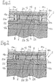
- the arrangement 2 shown in FIG. 1 shows sections the section through a pulley according to the invention (Toothed pulley) 4.
- This pulley 4 has in its middle Area 6 has a ring gear 8, while the edge areas 10a, 10b are cylindrical.
- This pulley (Toothed pulley) 4 is in engagement with a toothed belt 12.
- the in the figure downward running side of the Toothed belt 12 is on both of the edge regions 10a, 10b Toothed washer 4 corresponding edge zones 14a, 14b with a toothless (smooth) thickening strips (Reinforcing strips) 16a, 16b.
- the belt 12 has a Reinforcement insert 18 made of cord or fabric.
- the cylindrical regions 10a, 10b of the toothed disc 4 and the smooth thickening strips 16a, 16b of the toothed belt 12 designed such that the belt 12 in the area 14a, 14b the thickening strip 16 is not of the cylindrical Areas 10a, 10b of the disc 4 is supported. It is does not require the radius of the cylindrical areas 10a, 10b and the radius of the tooth base 30 of the disk 4 are identical to each other. It is crucial that when it runs out of the belt 12 on the disc 4 a certain distance between Thickening strips 16a, 16b and cylindrical area 10a, 10b the disc 4 remains.
- the belt / pulley arrangement shown in Fig. 2 differs from the arrangement described first in that the height 20a, 20b of the lateral Thickening strips 16a, 16b of the toothed belt 12 and the radius the cylindrical edge strips 10a, 10b of the disc 4 so are chosen to support the belt 12 during operation not only in the toothing area 6 but also an Support also in the cylindrical edge region 10a, 10b Disc is done.
- the arrangement shown in FIG. 3 differs from that shown in FIG. 1 not only in the larger width B of the belt / pulley arrangement 2.
- the belt 12 has a further thickening strip 16c in its center.
- This thickening strip 16c corresponds to a central cylindrical surface 10c of the pane 4.
- the overall dimensions are chosen such that the belt 12 is also radially supported in the region of the toothing 8.
- Fig. 4 represents a modification of that shown in Fig. 3 Arrangement. But similar to that shown in FIG. 2 also takes place here radial support of belt 12 over full width B.
Landscapes
- Engineering & Computer Science (AREA)
- General Engineering & Computer Science (AREA)
- Mechanical Engineering (AREA)
- Devices For Conveying Motion By Means Of Endless Flexible Members (AREA)
- Pulleys (AREA)
Abstract
Description
Grundlage der vorliegenden Erfindung ist ein aus Zahnriemen und
Zahnscheibe bestehender geräuscharmer Zahnriementrieb mit den
im Oberbegriff des Anspruchs 1 genannten Merkmalen.The basis of the present invention is a toothed belt and
Toothed pulley existing low-noise toothed belt drive with the
features mentioned in the preamble of
Ein bei Zahnriementrieben nach wie vor nicht befriedigend gelöstes Problem besteht in der Geräuschentwicklung, verursacht insbesondere durch den sogenannten Polygoneffekt. Unter Polygoneffekt versteht man das periodische Einknicken des Riemens im jeweils mit der Zahnscheibe in Eingriff stehenden Riemen-Zahngrund. Wegen der Unterbrechungen der Berührung Zahnriemen/Zahnscheibe ergibt sich eine periodische Radialschwingung des Riemens während des Abrollvorganges. Zusätzlich gibt es ein Aufschlaggeräusch, das beim Auftreffen flächiger Riemenzonen auf die Zahnscheibe entsteht.A still unsatisfactory with timing belt drives solved problem is the noise, caused especially through the so-called polygon effect. Under Polygon effect means the periodic buckling of the Belt in engagement with the pulley Belt tooth base. Because of the touch interruptions Timing belt / pulley results in a periodic Radial vibration of the belt during the unwinding process. In addition, there is an impact sound when it hits flat belt zones on the toothed pulley.
Bei Verwendung von bogenverzahnten Riemen erfolgt die periodische Berührung und Unterbrechung zwischen Riemen und Zahnscheibe nicht abrupt sondern gleitend. Eine harte Kontaktnahme nebst einer damit verbundenen Geräuschentwicklung läßt sich aber auch bei Bogenverzahnung nicht völlig vermeiden.When using curved toothed belts the periodic contact and interruption between belt and Toothed lock washer instead of abrupt but sliding. A tough one Contact along with the associated noise but can not be completely avoided even with curved teeth.
Der Patentschrift EP 0 389 741 A2 (DE 39 09 949 C2) liegt die Aufgabe zugrunde, den Umlauf eines Zahnriemens auf einer Zahnscheibe mit Hilfe einer mittig auf dem Zahnriemen angeordneten Längsrippe oder zwei seitlich angeordneten Längsrippen geräuschärmer zu gestalten. Diese mindestens eine Längsrippe, die Quernuten aufweist, korrespondiert zu mindestens einer in der Zahnscheibe befindlichen Längsnut. Um die Polygonwirkung zu bekämpfen, ist in der Längsnut ein Weichgummiring vorgesehen. Auf diese Weise laufen zwar die auf der Längsrippe durch die Quernuten gebildeten Klötze sanfter auf der Scheibe ab, der durch das Abrollen des sonstigen Zahnriemens auf der Riemenscheibe gegebene Polygoneffekt ist aber nach wie vor vorhanden. Dies kann durch den in der Längsrinne angeordneten Weichgummiring nicht verhindert werden.The patent specification EP 0 389 741 A2 (DE 39 09 949 C2) is the Task based on the circulation of a toothed belt on a Toothed pulley with the help of a center on the timing belt arranged longitudinal rib or two laterally arranged To design longitudinal ribs to be quieter. This at least one Longitudinal rib, which has transverse grooves, corresponds to at least one longitudinal groove in the toothed disc. Around Combating the polygon effect is in the longitudinal groove Soft rubber ring provided. In this way, they run up the longitudinal ribs formed by the transverse grooves more gently on the disc, which is caused by the rolling of the other Timing belt is given polygon effect on the pulley but still there. This can be done through the in the Soft rubber ring arranged in the longitudinal channel cannot be prevented.
Die Aufgabe der vorliegenden Erfindung, wie sie mit Anspruch 1
im wesentlichen gelöst ist, besteht in der Schaffung eines
Zahnriementriebs mit geräuschreduziertem Laufverhalten.The object of the present invention as set out in
Die Erfindung geht von der Erkenntnis aus, daß beim Eingriff eines Zahnriemens in eine Riemenscheibe zwischen den einzelnen Zahnblöcken aufgrund der dort vorhandenen geringen Riemendicke eine Art "Einknicken" entsteht, das zum Polygoneffekt beiträgt. Um diesem Einknicken entgegenzuwirken, wird erfindungsgemäß vorgeschlagen, einen auf der Zahnseite des Riemens anzubringenden wulstförmigen Verstärkungsstreifen mit dem Ziel vorzusehen, den Riemen im, Umlauf biegesteifer zu machen. Gemäß der Erfindung wird von einer Abstützung auf dem Kopfkreis ausgegangen. Die Zähne der Scheiben stützen den Zahnriemen im Nutgrund ab.The invention is based on the knowledge that during the intervention a timing belt in a pulley between each Tooth blocks due to the small belt thickness there a kind of "buckling" occurs, which contributes to the polygon effect. In order to counteract this buckling, the invention suggested one on the tooth side of the belt bead-like reinforcement strips to be attached with the aim to make the belt more rigid in the circulation. According to the invention is based on a support on the tip circle went out. The teeth of the pulleys support the timing belt in the Groove bottom.
Die Abstützung kann aber auch in den Zahnlücken der Zahnscheibe erfolgen. Besonders vorteilhaft im Hinblick auf eine Verminderung des Polygonwirkung ist es, wenn eine gleichmäßig auf den Zahnköpfen und Zahnlücken erfolgende Abstützung des Zahnriemens gewährleistet ist. Zu diesem Zweck wird - wegen der Elastizität des Riemenmaterials - die Höhe der Riemenzähne geringfügig höher ausgebildet als die Scheibennuten, um eine Abstützung des Riemens auch zwischen den Scheibenzähnen zu verwirklichen.The support can also be in the tooth gaps of the toothed disc respectively. Particularly advantageous with regard to a Decreasing the polygon effect is when a uniform support of the tooth heads and tooth gaps Timing belt is guaranteed. For this purpose - because of Elasticity of the belt material - the height of the belt teeth slightly higher than the disk grooves by one The belt is also supported between the pulley teeth realize.
Der umlaufende Verdickungsstreifen wird im wesentlichen kontaktfrei mit der Scheibenumfangsfläche durchgehend angeordnet. Es ist somit eine radiale Abstützung im Bereich der Festigkeitsträgerebene, der neutralen Faser, vorhanden.The circumferential thickening strip essentially becomes non-contact with the disc circumferential surface arranged. It is therefore a radial support in the area of Reinforcement layer, the neutral fiber, available.
Entsprechend eines alternativen Vorschlags ist eine leichte Abstützung des Verdickungsstreifens auf der Scheibenumfangsfläche realisiert. Hierdurch gibt es keine durchhängenden Querbereiche des Riemens, so daß die Festigkeitsträgerlage in einer Ebene auf gleichem radialen Niveau verbleibt, Dadurch nimmt die Festigkeitsträgerlage über ihre gesamte Breite gleichmäßig die Umfangskräfte auf. According to an alternative proposal is an easy one Support of the thickening strip on the Disk peripheral surface realized. As a result, there are none sagging transverse areas of the belt so that the Reinforcement layer in one plane on the same radial Level remains, This takes over the reinforcement layer their entire width evenly the circumferential forces.
Aus dem gesagten geht hervor, daß der wesentliche Grundgedanke der Erfindung in der weitgehenden Vermeidung eines "Einknickens" des Riemens im Rhythmus der Zahnfolge bzw. der Quernuten besteht, Dafür ist es nicht erforderlich, daß die wulstförmigen Längsränder des Riemens Laufstreifen nach Art eines Glattriemens bilden. Zur Unterdrückung des "Einknickens" genügt es, wenn die Längsränder des Riemens als bloße Verdickungs- bzw. Verstärkungsstreifen ausgebildet sind. Eine direkte Kontaktnahme mit dem jeweiligen glatten Rand der Riemenscheibe ist nicht erforderlich. Durch die Verdickungsstreifen wird der Riemen so biegesteif, daß eine radiale Abstützung auf der Verzahnung zugelassen werden kann. Erfindungswesentlich ist, daß die Verdickungsstreifen, die auf der Laufseite angeordnet sind, im Unterschied zu Längsstreifen gemäß dem Stand der Technik nicht durch Quernuten unterbrochen sind.From what has been said it follows that the essential basic idea the invention in largely avoiding a "Buckling" of the belt in the rhythm of the tooth sequence or the There are transverse grooves, it is not necessary for the beaded longitudinal edges of the belt tread according to Art form a smooth belt. To suppress the "buckling" it is sufficient if the longitudinal edges of the belt as bare Thickening or reinforcement strips are formed. A direct contact with the respective smooth edge of the Pulley is not required. Through the Thickening strips make the belt so rigid that a radial support on the teeth can be allowed. It is essential to the invention that the thickening strips that are on the running side are arranged, in contrast to longitudinal strips according to the prior art not interrupted by transverse grooves are.
Mit Hilfe des erfindungsgemäßen Zahnriementriebes ist eine formschlüssige Kraftübertragung, z. B. für Nockenwellen-Steuertriebe von Verbrennungsmotoren, bei gleichzeitiger Vermeidung des bisher üblichen negativen Polygoneffektes gegeben. With the help of the toothed belt drive according to the invention positive power transmission, e.g. B. for camshaft timing drives of internal combustion engines, with simultaneous Avoidance of the usual negative polygon effect given.
Bei größeren Riemenbreiten kann in der Riemenmitte ein weiterer Verdickungsstreifen zur zusätzlichen Versteifung und/oder Abstützung vorgesehen werden.For larger belt widths, another one can be found in the middle of the belt Thickening strips for additional stiffening and / or Support can be provided.
Durch Verwendung des erfindungsgemäßen Zahnriementriebes werden Polygoneffekt-Schwingungen vermieden, woraus ein geräuscharmer Lauf resultiert. Aufgrund einer besseren Stabilisierung durch die beidseitige Verbindung der Einzelzähne über die Verdickungsstreifen ergibt sich außerdem eine längere Riemenlebensdauer.By using the toothed belt drive according to the invention Polygon effect vibrations avoided, resulting in a low noise Run results. Because of better stabilization the bilateral connection of the individual teeth via the Thickening strips also result in a longer one Belt life.
Der erfindungsgemäße Zahnriementrieb ist prinzipiell für alle
Synchronantriebe (z. B. Nockenwellen-Steuertriebe,
Werkzeugmaschinen) einsetzbar. Er wird anhand der beigefügten
Zeichnungen näher erläutert; es zeigt:
Die in Fig. 1 dargestellte Anordnung 2 zeigt ausschnittsweise
den Schnitt durch eine erfindungsgemäße Riemenscheibe
(Zahnscheibe) 4. Diese Riemenscheibe 4 weist in ihrem mittleren
Bereich 6 einen Zahnkranz 8 auf, während die Randbereiche 10a,
10b zylindrisch gestaltet sind. Diese Riemenscheibe
(Zahnscheibe) 4 steht mit einem Zahnriemen 12 in Eingriff. Die
in der Abbildung nach unten gerichtete Laufseite des
Zahnriemens 12 ist an beiden zu den Randbereichen 10a, 10b der
Zahnscheibe 4 korrespondierenden Randzonen 14a, 14b mit einem
ungezahnten (glatten) Verdickungsstreifen
(Verstärkungsstreifen) 16a, 16b versehen.The
Zur Erhöhung der Zugfestigkeit weist der Riemen 12 eine
Verstärkungseinlage 18 aus Cord oder Gewebe auf. Die
zylindrischen Bereiche 10a, 10b der Zahnscheibe 4 und die
glatten Verdickungsstreifen 16a, 16b des Zahnriemens 12 sind
derartig ausgestaltet, daß der Riemen 12 im Bereich 14a, 14b
der Verdickungsstreifen 16 nicht von den zylindrischen
Bereichen 10a, 10b der Scheibe 4 abgestützt wird. Dabei ist es
nicht erforderlich, daß der Radius der zylindrischen Bereiche
10a, 10b und der Radius des Zahngrundes 30 der Scheibe 4
miteinander identisch sind. Entscheidend ist, daß beim Ablaufen
des Riemens 12 auf der Scheibe 4 ein gewisser Abstand zwischen
Verdickungsstreifen 16a, 16b und zylindrischem Bereich 10a, 10b
der Scheibe 4 verbleibt. To increase the tensile strength, the
Beim Betrieb des Zahnriementriebes 2 erfolgt eine Abstützung
des Riemens 12 ausschließlich im Verzahnungsbereich 6.
Die in Fig 2 dargestellte Riemen/Scheiben-Anordnung
unterscheidet sich von der zuerst beschriebenen Anordnung
dadurch, daß die Höhe 20a, 20b der seitlichen
Verdickungsstreifen 16a, 16b des Zahnriemens 12 und der Radius
der zylindrischen Randstreifen 10a, 10b der Scheibe 4 so
gewählt sind, daß beim Betrieb des Riemens 12 eine Abstützung
nicht nur im Verzahnungsbereich 6 sondern zusätzlich ein
Abstützung auch im zylindrischen Randbereich 10a, 10b der
Scheibe erfolgt.Support is provided during operation of the
Die in Fig. 3 dargestellte Anordnung unterscheidet sich von der
in Fig. 1 dargestellten nicht nur in der größeren Breite B der
Riemen/Scheiben-Anordnung 2. Zur zusätzlichen Führung weist der
Riemen 12 in seiner Mitte einen weiteren Verdickungsstreifen
16c auf. Dieser Verdickungsstreifen 16c korrespondiert zu einer
mittigen Zylinderfläche 10c der Scheibe 4.
Auch hierbei sind die Abmessungen insgesamt so gewählt, daß
auch hier die radiale Abstützung des Riemens 12 in dem Bereich
der Verzahnung 8 erfolgt.The arrangement shown in FIG. 3 differs from that shown in FIG. 1 not only in the larger width B of the belt /
Here, too, the overall dimensions are chosen such that the
Fig 4 stellt eine Abwandlung der in Fig. 3 dargestellten
Anordnung dar. Aber ähnlich wie gemäß Fig. 2 erfolgt auch hier
eine radiale Abstützung des Riemens 12 auf voller Breite B. Fig. 4 represents a modification of that shown in Fig. 3
Arrangement. But similar to that shown in FIG. 2 also takes place here
radial support of
- 22nd
- Antriebsanordnung, ZahnriementriebDrive arrangement, toothed belt drive
- 44th
- Riemenscheibe, ZahnscheibePulley, toothed pulley
- 66
- mittlerer Bereich der Riemenscheibe, Verzahnungsbereichmiddle area of the pulley, toothing area
- 88th
- Zahnkranz, Verzahnung, ZähneSprocket, gearing, teeth
- 10a, 10b10a, 10b
-
zylindrischer Bereich,
Randbereich der Riemenscheibecylindrical area,
Edge area of the pulley - 10c10c
- mittige Zylinderfläche der Scheibecentral cylindrical surface of the disc
- 1212th
- Zahnriemen, RiemenTiming belts, belts
- 14a, 14b14a, 14b
- Randzonen des ZahnriemensEdge zones of the timing belt
- 16a, 16b16a, 16b
- Verdickungsstreifen (Verstärkungsstreifen) des ZahnriemensThickening strips (reinforcement strips) of the timing belt
- 16c16c
- weiterer Verdickungsbereichfurther thickening area
- 1818th
- VerstärkungseinlageReinforcement insert
- 20a, 20b20a, 20b
-
Höhe des Verdickungsstreifens 16a, 16bHeight of the thickening
strip - 2222
- Höhe der VerzahnungTooth height
- BB
- Breite der Riemen/Scheiben-AnordnungWidth of the belt / pulley arrangement
- 2424th
- Riemen-ZahngrundBelt tooth base
- 2626
- Scheiben-ZahnkopfDisc tooth head
- 2828
- Riemen-ZahnkopfBelt tooth head
- 3030th
- Scheiben-ZahngrundDisc tooth base
Claims (2)
dadurch gekennzeichnet,
wobei seine Höhe (20a, ...) und der Radius des mindestens einen zylindrischen Bereichs (10a, ...) der Zahnscheibe (4) so gewählt sind,daß beim Betrieb des Riementriebs (2) eine Abstützung des Riemens (12) auf der Zahnscheibe (4) durch Kontakt zwischen Riemen-Zahngrund (24) und Scheiben-Zahnkopf (26) und/oder zwischen Riemen-Zahnkopf (28) und Scheiben-Zahngrund (30) erfolgt.
characterized,
The height (20a, ...) and the radius of the at least one cylindrical region (10a, ...) of the toothed pulley (4) are selected so that the belt (12) is supported when the belt drive (2) is in operation the toothed pulley (4) by contact between the belt tooth base (24) and the pulley tooth head (26) and / or between the belt tooth head (28) and the pulley tooth base (30).
dadurch gekennzeichnet,
characterized,
Applications Claiming Priority (2)
| Application Number | Priority Date | Filing Date | Title |
|---|---|---|---|
| DE19854849 | 1998-11-27 | ||
| DE1998154849 DE19854849A1 (en) | 1998-11-27 | 1998-11-27 | Low-noise toothed belt drive |
Publications (2)
| Publication Number | Publication Date |
|---|---|
| EP1004797A2 true EP1004797A2 (en) | 2000-05-31 |
| EP1004797A3 EP1004797A3 (en) | 2000-10-11 |
Family
ID=7889278
Family Applications (1)
| Application Number | Title | Priority Date | Filing Date |
|---|---|---|---|
| EP99123394A Withdrawn EP1004797A3 (en) | 1998-11-27 | 1999-11-24 | Low noise toothed belt drive |
Country Status (2)
| Country | Link |
|---|---|
| EP (1) | EP1004797A3 (en) |
| DE (1) | DE19854849A1 (en) |
Cited By (1)
| Publication number | Priority date | Publication date | Assignee | Title |
|---|---|---|---|---|
| DE10326512B4 (en) * | 2003-06-06 | 2008-04-10 | Aj Cybertron Gmbh | Timing belt guide without flanges |
Citations (1)
| Publication number | Priority date | Publication date | Assignee | Title |
|---|---|---|---|---|
| EP0389741A2 (en) | 1989-03-25 | 1990-10-03 | BRECO Kunststoffverarbeitungs-GmbH & Co. KG | Belt drive with toothed belt and pulley |
Family Cites Families (6)
| Publication number | Priority date | Publication date | Assignee | Title |
|---|---|---|---|---|
| US2724974A (en) * | 1951-09-18 | 1955-11-29 | White Sewing Machine Corp | Belt drive |
| US2770977A (en) * | 1953-11-27 | 1956-11-20 | Continental Gummi Werke Ag | Belt transmissions |
| FR1166734A (en) * | 1957-02-13 | 1958-11-14 | Belt drive device | |
| US4037485A (en) * | 1975-12-18 | 1977-07-26 | The Goodyear Tire & Rubber Company | Belt drive and belts and pulleys therefor |
| GB2188120B (en) * | 1985-06-28 | 1989-07-26 | Bruss Polt I | Toothed belt |
| JPH02199339A (en) * | 1989-10-23 | 1990-08-07 | Fuji Electric Co Ltd | Timing belt for conveyer device |
-
1998
- 1998-11-27 DE DE1998154849 patent/DE19854849A1/en not_active Withdrawn
-
1999
- 1999-11-24 EP EP99123394A patent/EP1004797A3/en not_active Withdrawn
Patent Citations (1)
| Publication number | Priority date | Publication date | Assignee | Title |
|---|---|---|---|---|
| EP0389741A2 (en) | 1989-03-25 | 1990-10-03 | BRECO Kunststoffverarbeitungs-GmbH & Co. KG | Belt drive with toothed belt and pulley |
Cited By (1)
| Publication number | Priority date | Publication date | Assignee | Title |
|---|---|---|---|---|
| DE10326512B4 (en) * | 2003-06-06 | 2008-04-10 | Aj Cybertron Gmbh | Timing belt guide without flanges |
Also Published As
| Publication number | Publication date |
|---|---|
| DE19854849A1 (en) | 2000-06-15 |
| EP1004797A3 (en) | 2000-10-11 |
Similar Documents
| Publication | Publication Date | Title |
|---|---|---|
| EP0601279B1 (en) | Toothed belt and V-belt apparatus for conveyors | |
| EP0925093B1 (en) | Moving walkway device | |
| DE3640354A1 (en) | DRIVE CHAIN | |
| DE102008033900A1 (en) | Low-noise chain | |
| CH636419A5 (en) | MECHANICAL POWER TRANSMISSION DEVICE. | |
| DE102005027328A1 (en) | Two-sided tooth chain | |
| DE3909950C2 (en) | Belt drive consisting of a toothed belt and a toothed pulley | |
| DE102010060933A1 (en) | Vehicle tires | |
| DE2527018C2 (en) | Vacuum belt filter system | |
| EP0778428B1 (en) | Chain guide and slide for motor vehicles | |
| DE19946554B4 (en) | Protective cover for attachment to a moving at least in one plane working organ | |
| CH628776A5 (en) | Belt for screening chain conveyors of potato-harvesting machines | |
| DE60205451T2 (en) | BELT ELEMENT FOR A DRIVE BELT FOR STEADLY CONTROLLED GEARBOX | |
| DE3233891C1 (en) | Toothed belt drive, especially for harvesting machines | |
| EP0599310A1 (en) | Door operator belt drive | |
| EP1066420B1 (en) | Machine for treating the surface of at least one textile web of endless fabric, especially for napping and/or emerizing or the like | |
| EP1004797A2 (en) | Low noise toothed belt drive | |
| EP1078179B1 (en) | Tooth belt drive mechanism | |
| DE60217935T3 (en) | SCREEN ARRANGEMENT FOR AN ELEVATOR SYSTEM | |
| EP1004796A2 (en) | Self-guiding toothed belt drive | |
| DE2906619C2 (en) | Timing belt | |
| EP0364992A2 (en) | Endless running belt for fitness training | |
| DE3737292C2 (en) | Endless drive belt | |
| DE3146975C2 (en) | ||
| DE2804549A1 (en) | Toothed belt drive esp. for a loom - has holes through belt retaining discs for passage of air |
Legal Events
| Date | Code | Title | Description |
|---|---|---|---|
| PUAI | Public reference made under article 153(3) epc to a published international application that has entered the european phase |
Free format text: ORIGINAL CODE: 0009012 |
|
| AK | Designated contracting states |
Kind code of ref document: A2 Designated state(s): AT BE CH CY DE DK ES FI FR GB GR IE IT LI LU MC NL PT SE |
|
| AX | Request for extension of the european patent |
Free format text: AL;LT;LV;MK;RO;SI |
|
| PUAL | Search report despatched |
Free format text: ORIGINAL CODE: 0009013 |
|
| AK | Designated contracting states |
Kind code of ref document: A3 Designated state(s): AT BE CH CY DE DK ES FI FR GB GR IE IT LI LU MC NL PT SE |
|
| AX | Request for extension of the european patent |
Free format text: AL;LT;LV;MK;RO;SI |
|
| RIC1 | Information provided on ipc code assigned before grant |
Free format text: 7F 16H 7/02 A, 7F 16G 1/28 B |
|
| STAA | Information on the status of an ep patent application or granted ep patent |
Free format text: STATUS: THE APPLICATION HAS BEEN WITHDRAWN |
|
| 18W | Application withdrawn |
Withdrawal date: 20001009 |