EP1003578B1 - Pump system - Google Patents
Pump system Download PDFInfo
- Publication number
- EP1003578B1 EP1003578B1 EP98903909A EP98903909A EP1003578B1 EP 1003578 B1 EP1003578 B1 EP 1003578B1 EP 98903909 A EP98903909 A EP 98903909A EP 98903909 A EP98903909 A EP 98903909A EP 1003578 B1 EP1003578 B1 EP 1003578B1
- Authority
- EP
- European Patent Office
- Prior art keywords
- chamber
- liquid medium
- pump system
- outlet
- chambers
- Prior art date
- Legal status (The legal status is an assumption and is not a legal conclusion. Google has not performed a legal analysis and makes no representation as to the accuracy of the status listed.)
- Expired - Lifetime
Links
Images


Classifications
-
- A—HUMAN NECESSITIES
- A61—MEDICAL OR VETERINARY SCIENCE; HYGIENE
- A61M—DEVICES FOR INTRODUCING MEDIA INTO, OR ONTO, THE BODY; DEVICES FOR TRANSDUCING BODY MEDIA OR FOR TAKING MEDIA FROM THE BODY; DEVICES FOR PRODUCING OR ENDING SLEEP OR STUPOR
- A61M5/00—Devices for bringing media into the body in a subcutaneous, intra-vascular or intramuscular way; Accessories therefor, e.g. filling or cleaning devices, arm-rests
- A61M5/14—Infusion devices, e.g. infusing by gravity; Blood infusion; Accessories therefor
- A61M5/168—Means for controlling media flow to the body or for metering media to the body, e.g. drip meters, counters ; Monitoring media flow to the body
- A61M5/16804—Flow controllers
- A61M5/16827—Flow controllers controlling delivery of multiple fluids, e.g. sequencing, mixing or via separate flow-paths
-
- A—HUMAN NECESSITIES
- A61—MEDICAL OR VETERINARY SCIENCE; HYGIENE
- A61M—DEVICES FOR INTRODUCING MEDIA INTO, OR ONTO, THE BODY; DEVICES FOR TRANSDUCING BODY MEDIA OR FOR TAKING MEDIA FROM THE BODY; DEVICES FOR PRODUCING OR ENDING SLEEP OR STUPOR
- A61M2206/00—Characteristics of a physical parameter; associated device therefor
- A61M2206/10—Flow characteristics
- A61M2206/22—Flow characteristics eliminating pulsatile flows, e.g. by the provision of a dampening chamber
Definitions
- the present invention relates to pump systems and, particularly, to pump systems used to pressurize fluids for use in medical procedures.
- contrast media are used in diagnostic procedures such as X-ray procedures (including, for example, angiography, venography and urography), CT scanning, magnetic resonance imaging (MRI), and ultrasonic imaging. Contrast media are also used during therapeutic procedures, including, for example, angioplasty and other interventional radiological procedures. Regardless of the type of procedure, any fluid injected into the patient must be sterile and contain a minimum of pyrogens.
- mechanized syringe injectors In the case of relatively high pressure applications, such as CT and angiography, mechanized syringe injectors are used.
- the use of mechanized syringe injectors also results in a number of substantial drawbacks.
- Current mechanisms for powering and controlling syringe pumps are complicated, inefficient and costly.
- Expensive and bulky pressure jackets for housing the syringe pumps are often required to prevent failure at high pressures.
- Syringe pumps are severely limited in that the maximum volume that can be injected at one time is the volume of the syringe.
- Disposable syringe pumps are costly.
- the flow rate acceleration of syringe injectors is limited by the inertia of the extensive drive train required to translate motor rotation into syringe plunger motion.
- contrast media are provided by manufacturers in numerous concentrations in sterilized containers (such as glass bottles or plastic packages) ranging incrementally in size from 20 ml to 200 ml. These containers are generally designed for a single use (that is, once a container is opened for a patient, it is used for that patient only).
- the contrast is generally aspirated from such containers via the syringe pump used to inject the contrast, and any contrast remaining in the container is discarded to prevent infection with potentially contaminated contrast.
- the hospital staff is faced with the task of choosing an appropriately sized contrast container to assure an optimum study while minimizing discarded contrast. Tune consuming procedures are required to reload the syringe if more contrast is required than originally calculated. On the other hand, expensive waste results if only a portion of a filled syringe is injected.
- the inventory of contrast containers required under the current system increases costs and regulatory burdens throughout the contrast media supplier-consumer chain.
- FR-A-2 715 310 discloses a pump for dispensing medical liquids which is powered by a drive mechanism and which comprises chambers attached to each other in generally linear, side-by-side alignment, each of the chambers having disposed therein a pressurizing mechanism to pressurize the liquid medium via generally linear motion of the pressurizing mechanism.
- US-A-3 447 479 discloses a syringe pump employing a series of similar syringes in which a fluid-pumping plunger is reciprocably movable.
- US-A-4 734 011 discloses a multicylinder single acting positive displacement pump used to move drilling fluid, water, crude oil, refined petroleum products and the like.
- the invention provides for a pump system according to claim 1.
- the present invention provides a pump system for use in pressurizing a liquid medium for injection into a patient.
- the pump system may also include a dampening chamber in fluid connection with the outlet flow of the pump system to decrease the pulsatile nature of the flow.
- Each chamber has disposed therein a pressurizing mechanism to pressurize liquid medium within the chamber.
- the pressurizing mechanism pressurizes the liquid medium via positive displacement thereof through generally linear motion of the pressurizing mechanism within the chamber.
- a piston Through reciprocating linear motion of the pressurizing mechanism by a piston, the liquid medium is alternatively drawn into the chamber from a source of liquid medium (for example, a container) and forced out of the chamber at a desired pressure.
- Generally linear, reciprocating motion can be provided by a number of pressurizing mechanisms including, but not limited to, pistons.
- Generally linear reciprocating motion can also be provided by a flexing element such as a diaphragm disposed within the chamber.
- a flexing element such as a diaphragm disposed within the chamber.
- Positive displacement through generally linear motion provides better volumetric efficiency than achievable through the use of rotational pumps.
- Volumetric efficiency can be defined as the volume of fluid actually delivered per unit mechanical displacement divided by the theoretical volume of fluid delivered per unit mechanical displacement. The volumetric efficiency of rotational pumps is undesirably dependent upon the pressure and flow rate of the liquid medium.
- Each chamber comprises an inlet port and an outlet port.
- the pump system also preferably comprises an inlet port check valve in fluid connection with each inlet port which allows the liquid medium to flow into the chamber through the inlet port, but substantially prevents the liquid medium from flowing out of the chamber through the inlet port.
- the pump system preferably comprises an outlet port check valve in fluid connection with each outlet port which allows pressurized liquid medium to flow out of the chamber through the outlet port, but substantially prevents the liquid medium from flowing into the chamber through the outlet port.
- Each inlet port is connected to a source of liquid medium.
- Each inlet port can be connected to different sources of varying liquid mediums in the case that mixing of varying liquid mediums is desired.
- Each outlet port is connected to a common outlet line for transmitting pressurized liquid medium to be injected into the patient.
- the pressurizing unit comprises at least three chambers. More preferably, the pressurizing unit comprises exactly three chambers.
- the present inventors have discovered that appropriately controlling the timing of the reciprocating motion of the pressurizing mechanism in each of three chambers enables control of the pump system to substantially reduce the pulsatile nature of flow commonly associated with pressurizing a liquid medium through reciprocal linear motion of a pressurizing mechanism.
- the pump system further comprises a drive mechanism in operative connection with the pressurizing mechanism of each chamber.
- the pressurizing unit is preferably readily releasable from connection with the drive mechanism. In this manner, those elements of the pump system which contact the liquid medium (that is, certain elements of the pressurizing unit) are easily removable for disposal or sterilization.
- the chambers, inlet ports and outlet ports of the pressurizing unit are molded from an integral piece of polymeric material.
- the chambers are in generally linear, side-by-side alignment in this embodiment.
- the pressurizing mechanism of each chamber preferably comprises a plunger or piston having a rearward extending member.
- the distal end of the extending member preferably extends beyond the rear of the chamber and comprises a cooperating connector (such as a flange) adapted to make a readily releasable connection of the extending member to the drive mechanism.
- the present invention further provides a pump system for cooperating with a powered drive mechanism to inject a liquid medium into a patient.
- the pump system comprises a disposable pump unit.
- the disposable pump unit comprises at least two chambers. Each of chambers is attached to each other chamber in generally linear, side-by-side alignment. Each of the chambers has disposed therein a pressurizing mechanism to pressurize the liquid medium via generally linear motion of the pressurizing mechanism.
- the pressurizing mechanism of each chamber comprises a connector to releasable connect the pressurizing mechanism of each chamber to the powered drive mechanism.
- the drive mechanisms of the pump systems of the present invention preferably comprises a timing mechanism to drive the pressurizing mechanism of each chamber in a timed fashion such that the flow rate and pressure of the liquid medium in the outlet line is substantially constant.
- the degree of pulsatile flow (as such term is defined below) is preferably maintained below 25%.
- the present invention also provides an injection system comprising one of the pump systems described above.
- the present invention comprises a method of using the pumps systems described above for injection of a fluid medium into a patient.
- the pump systems and injection systems of the present invention deliver pressurized fluid from a low-pressure container continuously without having to stop and reload as required with conventional syringe pumps.
- the pump or pressurizing units of the present pump systems can be constructed out of inexpensive, easily molded plastic parts that can be assembled with few steps in a high-volume production operation. These inexpensive pump units can be discarded after a single use.
- FIGS 1A through 7 illustrate one embodiment of a pump system 10 of the present invention.
- four chambers 20 of pressurizing unit 15 are in generally linear, side-by-side alignment (that is, the axes of chambers 20 are generally in the same plane).
- Each chamber 15 comprises an inlet port 25 and an outlet port 30.
- Inlet ports 25 and outlet ports 30 are preferably provided with check valves 40 to ensure the desired direction of flow is maintained.
- Inlet ports 25 are preferably in fluid connection with a common inlet channel 50, while outlet ports 30 are in fluid connection with a common outlet channel 60.
- pressurization unit 15 comprises a first or pump unit portion 15' and a second or head unit portion 15".
- First portion 15' comprises chambers 20, inlet ports 25 and outlet ports 30 and is preferably fabricated (for example, by injection molding) from an integral piece of polymeric material.
- Second portion 15" comprises inlet channel 50 and outlet channel 60. Like first portion 15', second portion 15" is preferably fabricated from an integral piece of polymeric material.
- Check valves 40 may comprise, for example, flexible disks that act as valves to allow unidirectional flow into or out of each chamber 20.
- Flexible check valves 40 can be made of rubber or a lightweight polymer.
- Check valves 40 can be easily inserted into appropriately shaped receptacles and are preferably held in place when first portion 15' and second portion 15" are bonded together as known in the polymer arts.
- each chamber 20 Disposed within each chamber 20 is a piston 70 suitable to alternatively draw the liquid medium into chamber 20 upon a downward or rearward (that is, away from second portion 15") stroke thereof and pressurize the liquid medium, forcing the pressurized liquid medium into outlet channel 60, upon an upward or forward stroke thereof.
- Motive force is provided to pistons 70 by an external motor-driven drive mechanism 100 that imparts reciprocating linear motion to piston 70.
- High pressures in outlet channel 60 are possible with the proper choice of materials and wall thickness. For example, a pressure of approximately 800 psi (55.16 bar) is attainable in the case of polypropylene chambers having an inner diameter of approximately .476 inches (1.209 cm) and a wall thickness of approximately .042 inches (0.107 cm).
- pistons 70 preferably comprise an elastomeric contact cover or surface 72.
- the circumference of contact surface 72 forms a sealing engagement with the sidewall of chamber 20.
- Contact surface 20 may be removably attachable to piston 70 via, for example, a flange 74.
- Piston 70 also preferably comprises a piston extension member 76 which extends rearward to exit chamber 20.
- piston 70' does not include a cover surface to contact the liquid medium. Rather, a sealing member such as an O-ring 72' is positioned between piston 70' and the inner wall of chamber 20'. As with piston 70, liquid medium is drawn into chamber 20' upon rearward motion of piston 70' and pressurized liquid medium is forced out of chamber 20' upon forward motion of piston 70'.
- a sealing member such as an O-ring 72'
- drive mechanism 100 comprises a cam shaft 110 which rotates to drive pistons 70 in a timed sequence chosen to reduce or substantially eliminate pulsatile flow.
- drive mechanism 100 preferably comprises drive extension members 120 which terminate on one end thereof in attachment members which cooperate with corresponding attachment members on piston extension members 76.
- slots 124 cooperate with flanges 78 to form a readily releasable connection between piston extension members 76 and drive extension members 120.
- Drive extension members 120 are preferably attached to cam shaft 110 via bearing assemblies 130 and contacting pins 126.
- bearing assemblies 130 preferably comprises a first bearing portion 132 and a second bearing portion 134 which are attached around cam shaft 110 via pins 136.
- cam shaft 110 is preferably powered by a motor 150 via belt 160.
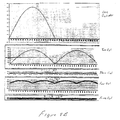
- Figure 8A illustrates the flow from each cylinder 20 as a function of shaft angle for three cylinders 20.
- the flow from each cylinder remains greater than 0 for only 180° of each 360° cycle. Flow less than 0 for any chamber is prevented because of check valves 40.
- the three flow curve (a, b and c) are summed together.
- K was chosen to be 0.8.
- the average flow (that is, the area under the "sum of the components" curve) was set to be the same for each study.
- the maximum flow rate (max flow) and minimum flow rate (min flow) vary based on this normalization.
- a degree or percent of pulsatile flow can be defined with the following equation: 100% * (max flow - min flow)/average flow
- Table 1 summarizes the results obtained for one through five chambers 20. These results are illustrated graphically in Figure 8B. Chambers Avg.
- the degree of pulsatile flow is maintained at or below 25%. At or below such a degree of pulsatile flow, the pulsatile nature of the flow is considered to be minimal for the purpose of the present invention. More preferably, the degree of pulsatile flow is maintained at or below 20%.
- the present inventors have discovered that with a minimum of three chambers 20 it is possible to develop a substantially steady fluid flow with minimal pulsatile component. Surprisingly, four chamber 20 are shown to have a greater degree of pulsatile flow than three chambers 20. In general, beyond four chambers 20, the degree of pulsatile flow continues to decrease. Adding more chambers 20 may allow a higher flow rate to be achieved with a shorter piston stroke length in each chamber 20. Additional chambers 20 may thus reduce wear and extend lifetime of pump system 10.
- pressurizing unit 15 While providing greater than three chambers 15 may increase the lifetime of pressurizing unit 15, it also increases manufacturing costs and manufacturing difficulty. It is desirable, however, to minimize the costs of pressurizing unit 15 in part so that pressurizing unit 15 (or at least those elements of pressurizing unit 15 that contact the liquid medium) may be discarded after use with a single patient. Disposal of pressurizing unit 15 after use with a single patient reduces the likelihood of cross-patient contamination. As three chambers 20 enable flow with a minimal pulsatile component at a minimum manufacturing cost, pressurizing unit 15 preferably comprises three chambers 20. Additionally, for any number of chambers 20, the degree of pulsatile flow can be decreased or substantially eliminated by including a damping chamber 660 (see Figure 11) in fluid connection with outlet channel 60.
- damping chambers have a mechanical capacitance provided by some type of distending member such as a balloon or bladder.
- a damping chamber suitable for use in the present invention is the FMI Pulse Dampener Model PD-60-LS or Model PD-HF available from Fluid Metering, Inc. of Oyster Bay, New York.
Abstract
Description
- The present invention relates to pump systems and, particularly, to pump systems used to pressurize fluids for use in medical procedures.
- In many medical procedures, such as drug delivery, it is desirable to inject a fluid into a patient. Likewise, numerous types of contrast media (often referred to simply as contrast) are injected into a patient for many diagnostic and therapeutic imaging procedures. For example, contrast media are used in diagnostic procedures such as X-ray procedures (including, for example, angiography, venography and urography), CT scanning, magnetic resonance imaging (MRI), and ultrasonic imaging. Contrast media are also used during therapeutic procedures, including, for example, angioplasty and other interventional radiological procedures. Regardless of the type of procedure, any fluid injected into the patient must be sterile and contain a minimum of pyrogens.
- A number of substantial problems arise in the use of current pumping systems and methods for injecting fluid into a patient's body. For example, it is often difficult to accurately control the pressure and flow rate of the fluid exiting the pumping system. In relatively low pressure applications, for example, peristaltic pumps have long been used. However, peristaltic pumps are difficult to control with accuracy.
- In the case of relatively high pressure applications, such as CT and angiography, mechanized syringe injectors are used. The use of mechanized syringe injectors also results in a number of substantial drawbacks. Current mechanisms for powering and controlling syringe pumps are complicated, inefficient and costly. Expensive and bulky pressure jackets for housing the syringe pumps are often required to prevent failure at high pressures. Syringe pumps are severely limited in that the maximum volume that can be injected at one time is the volume of the syringe. Disposable syringe pumps are costly. Moreover, the flow rate acceleration of syringe injectors is limited by the inertia of the extensive drive train required to translate motor rotation into syringe plunger motion.
- These and other drawbacks in currently available syringe pumping systems create and magnify a number of inefficiencies in current procedures for injecting contrast media. For example, a number of factors, including, but not limited to, the procedure to be performed and the size of the patient, determine: (i) the contrast to be used, (ii) the concentration thereof, and (iii) the amount to be injected. Under current practice of injecting contrast media via syringe pumping systems, hospitals must purchase and stock many contrast media concentrations in multiple container sizes in an attempt to provide the correct concentration and amount of a specific contrast for a specific procedure, while minimizing the wastage of contrast. In that regard, contrast is typically very expensive.
- Thus, most contrast media are provided by manufacturers in numerous concentrations in sterilized containers (such as glass bottles or plastic packages) ranging incrementally in size from 20 ml to 200 ml. These containers are generally designed for a single use (that is, once a container is opened for a patient, it is used for that patient only). The contrast is generally aspirated from such containers via the syringe pump used to inject the contrast, and any contrast remaining in the container is discarded to prevent infection with potentially contaminated contrast. The hospital staff is faced with the task of choosing an appropriately sized contrast container to assure an optimum study while minimizing discarded contrast. Tune consuming procedures are required to reload the syringe if more contrast is required than originally calculated. On the other hand, expensive waste results if only a portion of a filled syringe is injected. The inventory of contrast containers required under the current system increases costs and regulatory burdens throughout the contrast media supplier-consumer chain.
- Many of these costs, regulatory burdens and other problems associated with the use of multiple contrast containers can be substantially eliminated through use of relatively large contrast media containers for single- and multiple-patient use in connection with a pumping system allowing any volume and concentration of contrast to be injected as determined by the hospital staff before or during a procedure. Current syringe pumping systems simply do not provide a sufficiently cost-effective and efficient pumping system to provide optimal pressurization for injection of contrast and other liquid media.
- FR-A-2 715 310 discloses a pump for dispensing medical liquids which is powered by a drive mechanism and which comprises chambers attached to each other in generally linear, side-by-side alignment, each of the chambers having disposed therein a pressurizing mechanism to pressurize the liquid medium via generally linear motion of the pressurizing mechanism.
- US-A-3 447 479 discloses a syringe pump employing a series of similar syringes in which a fluid-pumping plunger is reciprocably movable.
- US-A-4 734 011 discloses a multicylinder single acting positive displacement pump used to move drilling fluid, water, crude oil, refined petroleum products and the like.
- It is, therefore, very desirable to develop injection systems and pump systems that reduce or eliminate the limitations associated with current injection systems and pump systems.
- The invention provides for a pump system according to claim 1.
- Preferred embodiments are described in the subclaims.
- The present invention provides a pump system for use in pressurizing a liquid medium for injection into a patient. The pump system may also include a dampening chamber in fluid connection with the outlet flow of the pump system to decrease the pulsatile nature of the flow.
- Each chamber has disposed therein a pressurizing mechanism to pressurize liquid medium within the chamber. The pressurizing mechanism pressurizes the liquid medium via positive displacement thereof through generally linear motion of the pressurizing mechanism within the chamber. Through reciprocating linear motion of the pressurizing mechanism by a piston, the liquid medium is alternatively drawn into the chamber from a source of liquid medium (for example, a container) and forced out of the chamber at a desired pressure.
- Generally linear, reciprocating motion can be provided by a number of pressurizing mechanisms including, but not limited to, pistons. Generally linear reciprocating motion can also be provided by a flexing element such as a diaphragm disposed within the chamber. In positive displacement of the liquid medium, there is generally a one-to-one correspondence between the length of the generally linear stroke of the pressurizing mechanism and the amount of liquid medium displaced. Positive displacement through generally linear motion provides better volumetric efficiency than achievable through the use of rotational pumps. Volumetric efficiency can be defined as the volume of fluid actually delivered per unit mechanical displacement divided by the theoretical volume of fluid delivered per unit mechanical displacement. The volumetric efficiency of rotational pumps is undesirably dependent upon the pressure and flow rate of the liquid medium.
- Each chamber comprises an inlet port and an outlet port. The pump system also preferably comprises an inlet port check valve in fluid connection with each inlet port which allows the liquid medium to flow into the chamber through the inlet port, but substantially prevents the liquid medium from flowing out of the chamber through the inlet port. Likewise, the pump system preferably comprises an outlet port check valve in fluid connection with each outlet port which allows pressurized liquid medium to flow out of the chamber through the outlet port, but substantially prevents the liquid medium from flowing into the chamber through the outlet port. Each inlet port is connected to a source of liquid medium. Each inlet port can be connected to different sources of varying liquid mediums in the case that mixing of varying liquid mediums is desired. If the volume displaced in each stroke is maintained relatively small, liquids of widely varying viscosity and density can be mixed without the use of mixing devices (for example, mechanical stirrers or rotary vane mixers) other than the present invention. Each outlet port is connected to a common outlet line for transmitting pressurized liquid medium to be injected into the patient.
- Preferably, the pressurizing unit comprises at least three chambers. More preferably, the pressurizing unit comprises exactly three chambers. The present inventors have discovered that appropriately controlling the timing of the reciprocating motion of the pressurizing mechanism in each of three chambers enables control of the pump system to substantially reduce the pulsatile nature of flow commonly associated with pressurizing a liquid medium through reciprocal linear motion of a pressurizing mechanism.
- The pump system further comprises a drive mechanism in operative connection with the pressurizing mechanism of each chamber. The pressurizing unit is preferably readily releasable from connection with the drive mechanism. In this manner, those elements of the pump system which contact the liquid medium (that is, certain elements of the pressurizing unit) are easily removable for disposal or sterilization.
- In a preferred embodiment, the chambers, inlet ports and outlet ports of the pressurizing unit are molded from an integral piece of polymeric material. Preferably, the chambers are in generally linear, side-by-side alignment in this embodiment. The pressurizing mechanism of each chamber preferably comprises a plunger or piston having a rearward extending member. The distal end of the extending member preferably extends beyond the rear of the chamber and comprises a cooperating connector (such as a flange) adapted to make a readily releasable connection of the extending member to the drive mechanism.
- The present invention further provides a pump system for cooperating with a powered drive mechanism to inject a liquid medium into a patient. The pump system comprises a disposable pump unit. The disposable pump unit comprises at least two chambers. Each of chambers is attached to each other chamber in generally linear, side-by-side alignment. Each of the chambers has disposed therein a pressurizing mechanism to pressurize the liquid medium via generally linear motion of the pressurizing mechanism. The pressurizing mechanism of each chamber comprises a connector to releasable connect the pressurizing mechanism of each chamber to the powered drive mechanism.
- The drive mechanisms of the pump systems of the present invention preferably comprises a timing mechanism to drive the pressurizing mechanism of each chamber in a timed fashion such that the flow rate and pressure of the liquid medium in the outlet line is substantially constant. In that regard, the degree of pulsatile flow (as such term is defined below) is preferably maintained below 25%.
- The present invention also provides an injection system comprising one of the pump systems described above. Likewise, the present invention comprises a method of using the pumps systems described above for injection of a fluid medium into a patient. The pump systems and injection systems of the present invention deliver pressurized fluid from a low-pressure container continuously without having to stop and reload as required with conventional syringe pumps. The pump or pressurizing units of the present pump systems can be constructed out of inexpensive, easily molded plastic parts that can be assembled with few steps in a high-volume production operation. These inexpensive pump units can be discarded after a single use.
-
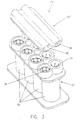
- Figure 1A illustrates an embodiment of a pressurizing unit of the present invention.
- Figure 1B illustrates the pressurizing unit of Figure 1A showing several subassemblies thereof.
- Figure 1C illustrates a cross-sectional view of an alternative embodiment of a piston for use in a pressurizing unit of the present invention.
- Figure 2A illustrates a partially cut-away view of the pressurizing unit of Figure 1A showing the pressurizing mechanisms (pistons) within the chambers.
- Figure 2B illustrates a partially cut-away view of the pressurizing unit of Figure 1A with the inlet and outlet channel portion and the pistons removed.
- Figure 3 illustrates a top perspective view of the pressurizing unit of Figure 1A.
- Figure 4 illustrates a front, cross-sectional view of the pressurizing unit of Figure 1A.
- Figure 5 illustrates an expanded, front cross-sectional view of an inlet port and outlet port of a single chamber.
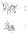
- Figure 6A illustrates a partially cut-away view of an embodiment of a drive mechanism for use with the pressurizing unit of Figure 1.
- Figure 6B illustrates a partially cut-away view of the drive mechanism of Figure 6A showing several subassemblies thereof.
- Figure 6C illustrates a top perspective view of the drive mechanism of Figure 6A.
- Figure 6D illustrates a bottom perspective view of the drive mechanism of Figure 6A.
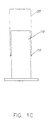
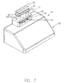
- Figure 7 illustrates a perspective view of a pump system comprising the pressurizing unit of Figure 1 and the drive mechanism of Figures 6A through 6D in releasable connection.
- Figure 8A illustrates the flow from each cylinder in a three-cylinder pressurizing unit as a function of shaft angle.
- Figure 8B illustrates the flow from pressurizing units comprising one, two, three, four and five cylinders.
-
- Figures 1A through 7 illustrate one embodiment of a
pump system 10 of the present invention. In this embodiment, fourchambers 20 of pressurizingunit 15 are in generally linear, side-by-side alignment (that is, the axes ofchambers 20 are generally in the same plane). Eachchamber 15 comprises aninlet port 25 and anoutlet port 30. -
Inlet ports 25 andoutlet ports 30 are preferably provided withcheck valves 40 to ensure the desired direction of flow is maintained.Inlet ports 25 are preferably in fluid connection with acommon inlet channel 50, whileoutlet ports 30 are in fluid connection with acommon outlet channel 60. - In this embodiment,
pressurization unit 15 comprises a first or pump unit portion 15' and a second orhead unit portion 15". First portion 15' compriseschambers 20,inlet ports 25 andoutlet ports 30 and is preferably fabricated (for example, by injection molding) from an integral piece of polymeric material.Second portion 15" comprisesinlet channel 50 andoutlet channel 60. Like first portion 15',second portion 15" is preferably fabricated from an integral piece of polymeric material. - Check
valves 40 may comprise, for example, flexible disks that act as valves to allow unidirectional flow into or out of eachchamber 20.Flexible check valves 40 can be made of rubber or a lightweight polymer. Checkvalves 40 can be easily inserted into appropriately shaped receptacles and are preferably held in place when first portion 15' andsecond portion 15" are bonded together as known in the polymer arts. - Disposed within each
chamber 20 is apiston 70 suitable to alternatively draw the liquid medium intochamber 20 upon a downward or rearward (that is, away fromsecond portion 15") stroke thereof and pressurize the liquid medium, forcing the pressurized liquid medium intooutlet channel 60, upon an upward or forward stroke thereof. Motive force is provided topistons 70 by an external motor-drivendrive mechanism 100 that imparts reciprocating linear motion topiston 70. High pressures inoutlet channel 60 are possible with the proper choice of materials and wall thickness. For example, a pressure of approximately 800 psi (55.16 bar) is attainable in the case of polypropylene chambers having an inner diameter of approximately .476 inches (1.209 cm) and a wall thickness of approximately .042 inches (0.107 cm). - In the illustrated embodiment,
pistons 70 preferably comprise an elastomeric contact cover orsurface 72. The circumference ofcontact surface 72 forms a sealing engagement with the sidewall ofchamber 20.Contact surface 20 may be removably attachable topiston 70 via, for example, aflange 74.Piston 70 also preferably comprises apiston extension member 76 which extends rearward to exitchamber 20. - An alternative embodiment is illustrated in Figure 1C. In this embodiment, piston 70' does not include a cover surface to contact the liquid medium. Rather, a sealing member such as an O-ring 72' is positioned between piston 70' and the inner wall of chamber 20'. As with
piston 70, liquid medium is drawn into chamber 20' upon rearward motion of piston 70' and pressurized liquid medium is forced out of chamber 20' upon forward motion of piston 70'. - Preferably,
drive mechanism 100 comprises acam shaft 110 which rotates to drivepistons 70 in a timed sequence chosen to reduce or substantially eliminate pulsatile flow. As illustrated in Figures 6A through 7,drive mechanism 100 preferably comprisesdrive extension members 120 which terminate on one end thereof in attachment members which cooperate with corresponding attachment members onpiston extension members 76. As best illustrated in Figure 7,slots 124 cooperate withflanges 78 to form a readily releasable connection betweenpiston extension members 76 and driveextension members 120. - Drive
extension members 120 are preferably attached tocam shaft 110 via bearingassemblies 130 and contactingpins 126. As illustrated in Figure6B bearing assemblies 130 preferably comprises afirst bearing portion 132 and asecond bearing portion 134 which are attached aroundcam shaft 110 viapins 136. As best illustrated in Figure 6D,cam shaft 110 is preferably powered by amotor 150 viabelt 160. - Several studies of the effect of the number of
chambers 20 on the pulsatile nature of the flow are illustrated in Figures 8A and 8B. Figure 8A illustrates the flow from eachcylinder 20 as a function of shaft angle for threecylinders 20. The flow from each cylinder remains greater than 0 for only 180° of each 360° cycle. Flow less than 0 for any chamber is prevented because ofcheck valves 40. The three flow curve (a, b and c) are summed together. In general, the flow rate (as a function of time in seconds) is provided by the following equations:
pos designates that only the positive part of each sine wave is added; and
ω is the rate of rotation in degrees per second. - In the present calculations, K was chosen to be 0.8. The average flow rate (avg flow) per 360-degree cycle can be shown to be K/π = .254. The average flow (that is, the area under the "sum of the components" curve) was set to be the same for each study. The maximum flow rate (max flow) and minimum flow rate (min flow) vary based on this normalization. A degree or percent of pulsatile flow can be defined with the following equation:
chambers 20. These results are illustrated graphically in Figure 8B.Chambers Avg. Flow Min Flow Max Flow Degree of Pulsatile Flow 1 .254 0 .8 315% 2 .254 0 .4 157% 3 .254 .236 .271 14% 4 .254 .243 .283 31% 5 .254 .249 .261 5% - Preferably, the degree of pulsatile flow is maintained at or below 25%. At or below such a degree of pulsatile flow, the pulsatile nature of the flow is considered to be minimal for the purpose of the present invention. More preferably, the degree of pulsatile flow is maintained at or below 20%. The present inventors have discovered that with a minimum of three
chambers 20 it is possible to develop a substantially steady fluid flow with minimal pulsatile component. Surprisingly, fourchamber 20 are shown to have a greater degree of pulsatile flow than threechambers 20. In general, beyond fourchambers 20, the degree of pulsatile flow continues to decrease. Addingmore chambers 20 may allow a higher flow rate to be achieved with a shorter piston stroke length in eachchamber 20.Additional chambers 20 may thus reduce wear and extend lifetime ofpump system 10. - While providing greater than three
chambers 15 may increase the lifetime of pressurizingunit 15, it also increases manufacturing costs and manufacturing difficulty. It is desirable, however, to minimize the costs of pressurizingunit 15 in part so that pressurizing unit 15 (or at least those elements of pressurizingunit 15 that contact the liquid medium) may be discarded after use with a single patient. Disposal of pressurizingunit 15 after use with a single patient reduces the likelihood of cross-patient contamination. As threechambers 20 enable flow with a minimal pulsatile component at a minimum manufacturing cost, pressurizingunit 15 preferably comprises threechambers 20. Additionally, for any number ofchambers 20, the degree of pulsatile flow can be decreased or substantially eliminated by including a damping chamber 660 (see Figure 11) in fluid connection withoutlet channel 60. In general, such damping chambers have a mechanical capacitance provided by some type of distending member such as a balloon or bladder. An example of a damping chamber suitable for use in the present invention is the FMI Pulse Dampener Model PD-60-LS or Model PD-HF available from Fluid Metering, Inc. of Oyster Bay, New York.
Claims (5)
- A pump system for cooperating with a powered drive mechanism to inject a liquid medium into a patient, the pump system comprising a pump unit (15), the pump unit comprising at least two chambers (20), each of the chambers having an inlet port (25) and an outlet port (30) and being attached to each other chamber in linear, side-by-side alignment, each of the chambers having disposed therein a piston (70) to pressurize the liquid medium via linear motion,
characterized in that
the pump unit (15) is disposable, the piston (70) of each chamber comprises a connector (78) to releasable connect the piston (70) of each chamber (20) to the powered drive mechanism (100) and the disposable pump unit comprises an integral head unit (15") comprising a common outlet channel (60) connectable with a common outlet line, the common outlet channel (60) being in fluid connection with the outlet ports (30) and a common inlet channel (50) being in fluid connection with the inlet ports (25). - The pump system of claim 1 wherein the disposable pump unit (15) comprises three chambers (20).
- The pump system of claim 1 or 2 wherein the piston (70) comprises a rearward extending member (76) having a connector (78) on a distal end thereof to releasably connect the extending member (76) to the drive mechanism.
- The pump system of any one of claims 1-3 wherein the inlet port of each chamber (20) is in fluid connection with an inlet port check valve (40) adapted to allow the liquid medium to flow into the chamber through the inlet port and to substantially prevent the liquid medium from flowing out of the chamber through the inlet port, the outlet port of each chamber being in fluid connection with an outlet port check valve (40) adapted to allow pressurized liquid medium to flow out of the chamber through the outlet port and to substantially prevent the liquid medium from flowing into the chamber through the outlet port, the common inlet channel being connectable to a liquid medium source, each outlet port being connected to the common outlet line (60) for transmitting pressurized liquid medium to the patient.
- The pump system of any one of claims 1-4 wherein the disposable pumping unit (15) is molded from an integral piece of polymeric material.
Applications Claiming Priority (3)
| Application Number | Priority Date | Filing Date | Title |
|---|---|---|---|
| US801706 | 1997-02-14 | ||
| US08/801,706 US5916197A (en) | 1997-02-14 | 1997-02-14 | Injection system, pump system for use therein and method of use of pumping system |
| PCT/US1998/002027 WO1998035712A1 (en) | 1997-02-14 | 1998-02-05 | Injection system, pump system for use therein and method of use of pumping system |
Publications (2)
| Publication Number | Publication Date |
|---|---|
| EP1003578A1 EP1003578A1 (en) | 2000-05-31 |
| EP1003578B1 true EP1003578B1 (en) | 2005-04-06 |
Family
ID=25181850
Family Applications (1)
| Application Number | Title | Priority Date | Filing Date |
|---|---|---|---|
| EP98903909A Expired - Lifetime EP1003578B1 (en) | 1997-02-14 | 1998-02-05 | Pump system |
Country Status (7)
| Country | Link |
|---|---|
| US (2) | US5916197A (en) |
| EP (1) | EP1003578B1 (en) |
| JP (1) | JP2001512342A (en) |
| AT (1) | ATE292485T1 (en) |
| AU (1) | AU6055298A (en) |
| DE (1) | DE69829669T2 (en) |
| WO (1) | WO1998035712A1 (en) |
Families Citing this family (80)
| Publication number | Priority date | Publication date | Assignee | Title |
|---|---|---|---|---|
| US8082018B2 (en) * | 1995-04-20 | 2011-12-20 | Acist Medical Systems, Inc. | System and method for multiple injection procedures on heart vessels |
| US20030028145A1 (en) * | 1995-04-20 | 2003-02-06 | Duchon Douglas J. | Angiographic injector system with multiple processor redundancy |
| US6656157B1 (en) * | 1995-04-20 | 2003-12-02 | Acist Medical Systems, Inc. | Infinitely refillable syringe |
| US7267666B1 (en) | 1995-04-20 | 2007-09-11 | Acist Medical Systems, Inc. | Angiographic injector system with multiple processor redundancy |
| US6099502A (en) * | 1995-04-20 | 2000-08-08 | Acist Medical Systems, Inc. | Dual port syringe |
| US5916197A (en) * | 1997-02-14 | 1999-06-29 | Medrad, Inc. | Injection system, pump system for use therein and method of use of pumping system |
| ES2252871T3 (en) * | 1997-11-07 | 2006-05-16 | Acist Medical Systems, Inc. | ANGIOGRAPHIC INJECTOR SYSTEM WITH MULTIPLE FLUID PROCESSOR. |
| AU4185600A (en) * | 1999-04-01 | 2000-10-23 | Acist Medical Systems, Inc. | An integrated medical information management and medical device control system and method |
| WO2001013785A2 (en) * | 1999-08-20 | 2001-03-01 | Acist Medical Systems, Inc. | Apparatus and method of detecting fluid |
| US6669679B1 (en) | 2000-01-07 | 2003-12-30 | Acist Medical Systems, Inc. | Anti-recoil catheter |
| US6626862B1 (en) * | 2000-04-04 | 2003-09-30 | Acist Medical Systems, Inc. | Fluid management and component detection system |
| US6471674B1 (en) | 2000-04-21 | 2002-10-29 | Medrad, Inc. | Fluid delivery systems, injector systems and methods of fluid delivery |
| US6673048B1 (en) | 2000-05-24 | 2004-01-06 | Acist Medical Systems, Inc. | Pressure sleeve assembly |
| WO2002007812A2 (en) * | 2000-07-20 | 2002-01-31 | Acist Medical Systems, Inc. | Syringe plunger locking mechanism |
| US8489176B1 (en) | 2000-08-21 | 2013-07-16 | Spectrum Dynamics Llc | Radioactive emission detector equipped with a position tracking system and utilization thereof with medical systems and in medical procedures |
| US8565860B2 (en) | 2000-08-21 | 2013-10-22 | Biosensors International Group, Ltd. | Radioactive emission detector equipped with a position tracking system |
| US8909325B2 (en) | 2000-08-21 | 2014-12-09 | Biosensors International Group, Ltd. | Radioactive emission detector equipped with a position tracking system and utilization thereof with medical systems and in medical procedures |
| EP2253340A1 (en) | 2000-08-24 | 2010-11-24 | Cordis Corporation | Fluid delivery systems for delivering fluids to multi-lumen catheters |
| US7094216B2 (en) | 2000-10-18 | 2006-08-22 | Medrad, Inc. | Injection system having a pressure isolation mechanism and/or a handheld controller |
| US7018363B2 (en) | 2001-01-18 | 2006-03-28 | Medrad, Inc. | Encoding and sensing of syringe information |
| US7566320B2 (en) * | 2001-02-14 | 2009-07-28 | Acist Medical Systems, Inc. | Fluid injector system |
| WO2002064195A2 (en) * | 2001-02-14 | 2002-08-22 | Acist Medical Systems, Inc. | Catheter fluid control system |
| WO2002065114A2 (en) * | 2001-02-15 | 2002-08-22 | Acist Medical Systems, Inc. | Systems and methods for detection and measurement of elements in a medium |
| US7308300B2 (en) * | 2001-05-30 | 2007-12-11 | Acist Medical Systems, Inc. | Medical injection system |
| US7174240B2 (en) * | 2001-10-19 | 2007-02-06 | Cardiovascular Systems, Inc. | Control system for rotational angioplasty device |
| EP2272423B1 (en) * | 2001-12-07 | 2016-04-13 | ACIST Medical Systems, Inc. | Fluid valve which blocks output by high pressure input |
| US6880808B2 (en) | 2002-05-03 | 2005-04-19 | Acist Medical Systems, Inc. | Gamma-stable high pressure stopcock |
| FR2856306B1 (en) * | 2003-06-17 | 2005-09-16 | Sedat | MEDICAL DEVICE FOR DISPENSING AT LEAST ONE FLUID |
| US9470801B2 (en) | 2004-01-13 | 2016-10-18 | Spectrum Dynamics Llc | Gating with anatomically varying durations |
| WO2008010227A2 (en) | 2006-07-19 | 2008-01-24 | Spectrum Dynamics Llc | Imaging protocols |
| US7968851B2 (en) | 2004-01-13 | 2011-06-28 | Spectrum Dynamics Llc | Dynamic spect camera |
| US8571881B2 (en) | 2004-11-09 | 2013-10-29 | Spectrum Dynamics, Llc | Radiopharmaceutical dispensing, administration, and imaging |
| WO2005067383A2 (en) | 2004-01-13 | 2005-07-28 | Spectrum Dynamics Llc | Multi-dimensional image reconstruction |
| US8586932B2 (en) | 2004-11-09 | 2013-11-19 | Spectrum Dynamics Llc | System and method for radioactive emission measurement |
| DE102004021035B3 (en) * | 2004-04-07 | 2005-11-17 | Erbe Elektromedizin Gmbh | Apparatus for waterjet surgery |
| EP1778957A4 (en) | 2004-06-01 | 2015-12-23 | Biosensors Int Group Ltd | Radioactive-emission-measurement optimization to specific body structures |
| US8615405B2 (en) | 2004-11-09 | 2013-12-24 | Biosensors International Group, Ltd. | Imaging system customization using data from radiopharmaceutical-associated data carrier |
| US9316743B2 (en) | 2004-11-09 | 2016-04-19 | Biosensors International Group, Ltd. | System and method for radioactive emission measurement |
| US9943274B2 (en) | 2004-11-09 | 2018-04-17 | Spectrum Dynamics Medical Limited | Radioimaging using low dose isotope |
| EP1827505A4 (en) | 2004-11-09 | 2017-07-12 | Biosensors International Group, Ltd. | Radioimaging |
| US8000773B2 (en) | 2004-11-09 | 2011-08-16 | Spectrum Dynamics Llc | Radioimaging |
| US20060211989A1 (en) | 2005-03-04 | 2006-09-21 | Rhinehart Edward J | Fluid delivery systems, devices and methods for delivery of fluids |
| US9011377B2 (en) | 2008-11-05 | 2015-04-21 | Bayer Medical Care Inc. | Fluid mixing control device for a multi-fluid delivery system |
| US9433730B2 (en) | 2013-03-14 | 2016-09-06 | Bayer Healthcare Llc | Fluid mixing control device for a multi-fluid delivery system |
| US7766883B2 (en) | 2007-10-30 | 2010-08-03 | Medrad, Inc. | System and method for proportional mixing and continuous delivery of fluids |
| US8837793B2 (en) | 2005-07-19 | 2014-09-16 | Biosensors International Group, Ltd. | Reconstruction stabilizer and active vision |
| EP1909853B1 (en) | 2005-07-19 | 2015-03-18 | Biosensors International Group, Ltd. | Imaging protocols |
| WO2007076463A2 (en) * | 2005-12-27 | 2007-07-05 | Acist Medical Systems, Inc. | Balloon inflation device |
| US8894974B2 (en) | 2006-05-11 | 2014-11-25 | Spectrum Dynamics Llc | Radiopharmaceuticals for diagnosis and therapy |
| US8610075B2 (en) | 2006-11-13 | 2013-12-17 | Biosensors International Group Ltd. | Radioimaging applications of and novel formulations of teboroxime |
| WO2008075362A2 (en) | 2006-12-20 | 2008-06-26 | Spectrum Dynamics Llc | A method, a system, and an apparatus for using and processing multidimensional data |
| US8172799B2 (en) * | 2007-01-10 | 2012-05-08 | Acist Medical Systems, Inc. | Volumetric pump |
| USD942005S1 (en) | 2007-03-14 | 2022-01-25 | Bayer Healthcare Llc | Orange syringe plunger cover |
| USD1002840S1 (en) | 2007-03-14 | 2023-10-24 | Bayer Healthcare Llc | Syringe plunger |
| USD847985S1 (en) | 2007-03-14 | 2019-05-07 | Bayer Healthcare Llc | Syringe plunger cover |
| US8521253B2 (en) | 2007-10-29 | 2013-08-27 | Spectrum Dynamics Llc | Prostate imaging |
| CN101939540B (en) | 2007-12-10 | 2013-10-23 | 梅德拉股份有限公司 | Continuous fluid delivery system and method |
| US8608484B2 (en) | 2008-03-04 | 2013-12-17 | Medrad, Inc. | Dynamic anthropomorphic cardiovascular phantom |
| EP2448614B1 (en) | 2009-07-01 | 2018-10-10 | Fresenius Medical Care Holdings, Inc. | Drug delivery devices and related systems and methods |
| US8338788B2 (en) | 2009-07-29 | 2012-12-25 | Spectrum Dynamics Llc | Method and system of optimized volumetric imaging |
| US8281807B2 (en) | 2009-08-31 | 2012-10-09 | Medrad, Inc. | Fluid path connectors and container spikes for fluid delivery |
| DE102009057070B9 (en) * | 2009-12-04 | 2012-11-29 | Maquet Gmbh & Co. Kg | Piston machine for use as a vacuum pump for medical purposes |
| US9480791B2 (en) * | 2009-12-21 | 2016-11-01 | Bayer Healthcare Llc | Pumping devices, systems and methods for use with medical fluids including compensation for variations in pressure or flow rate |
| WO2011153457A1 (en) | 2010-06-04 | 2011-12-08 | Medrad, Inc. | System and method for planning and monitoring multi-dose radiopharmaceutical usage on radiopharmaceutical injectors |
| US8944780B2 (en) | 2011-03-25 | 2015-02-03 | Bayer Medical Care Inc. | Pumping devices, systems including multiple pistons and methods for use with medical fluids |
| US10064987B2 (en) | 2011-01-31 | 2018-09-04 | Fresenius Medical Care Holdings, Inc. | Preventing over-delivery of drug |
| EP2673018B1 (en) | 2011-02-08 | 2019-04-10 | Fresenius Medical Care Holdings, Inc. | Magnetic sensors and related systems and methods |
| CN106975117A (en) * | 2011-09-21 | 2017-07-25 | 拜耳医药保健有限责任公司 | Continuous multiple fluid pump device, driving and actuating system and method |
| JP6379033B2 (en) * | 2012-04-06 | 2018-08-22 | 厚夫 森 | Automatic rapid infusion or blood transfusion device |
| US9144646B2 (en) | 2012-04-25 | 2015-09-29 | Fresenius Medical Care Holdings, Inc. | Vial spiking devices and related assemblies and methods |
| US9511186B1 (en) | 2012-10-23 | 2016-12-06 | Acist Medical Systems, Inc. | Medical injection systems and pumps |
| US9107986B2 (en) | 2013-03-11 | 2015-08-18 | Boston Scientific Limited | Double action infusion pump |
| US9925331B2 (en) | 2013-03-11 | 2018-03-27 | Boston Scientific Limited | Double action infusion system |
| US9714650B2 (en) | 2013-06-11 | 2017-07-25 | Matthew G. Morris, Jr. | Pumping system |
| WO2015106107A1 (en) | 2014-01-10 | 2015-07-16 | Bayer Medical Care Inc. | Single-use disposable set connector |
| CA2942754C (en) | 2014-03-19 | 2019-10-15 | Bayer Healthcare Llc | System for syringe engagement to an injector |
| JP6749918B2 (en) | 2015-01-09 | 2020-09-02 | バイエル・ヘルスケア・エルエルシーBayer HealthCare LLC | Multi-fluid delivery system with multi-use disposable set and features thereof |
| CN112999464B (en) | 2015-08-28 | 2023-04-18 | 拜耳医药保健有限公司 | Systems and methods for syringe fluid fill verification and image recognition of power injector system features |
| WO2017218372A1 (en) | 2016-06-15 | 2017-12-21 | Bayer Healthcare Llc | Multi-use disposable system and syringe therefor |
| EP4133180A1 (en) | 2020-04-06 | 2023-02-15 | Robert E. Mayle, Jr. | Injection device |
Family Cites Families (29)
| Publication number | Priority date | Publication date | Assignee | Title |
|---|---|---|---|---|
| GB511715A (en) * | 1938-03-29 | 1939-08-23 | Standard Pressed Steel Co | Improvements in or relating to vehicle suspension systems |
| US3447479A (en) * | 1967-06-02 | 1969-06-03 | Pall Corp | Syringe pump |
| US3949746A (en) * | 1974-09-03 | 1976-04-13 | Animal Systems, Inc. | Animal injector apparatus |
| GB1511715A (en) * | 1974-11-04 | 1978-05-24 | Dresser Ind | Multiplex pump |
| US3993061A (en) * | 1975-02-28 | 1976-11-23 | Ivac Corporation | Syringe pump drive system and disposable syringe cartridge |
| US3994294A (en) * | 1975-02-28 | 1976-11-30 | Ivac Corporation | Syringe pump valving and motor direction control system |
| US4475666A (en) * | 1981-08-31 | 1984-10-09 | American Hospital Supply Corporation | Automated liquid dispenser control |
| US4563175A (en) * | 1983-12-19 | 1986-01-07 | Lafond Margaret | Multiple syringe pump |
| US4846797A (en) * | 1985-05-14 | 1989-07-11 | Intelligent Medicine, Inc. | Syringe positioning device for enhancing fluid flow control |
| US4734011A (en) * | 1986-08-01 | 1988-03-29 | Texaco Inc. | Pulsation dampener for reciprocating pumps |
| US4795441A (en) * | 1987-04-16 | 1989-01-03 | Bhatt Kunjlata M | Medication administration system |
| US4898579A (en) * | 1987-06-26 | 1990-02-06 | Pump Controller Corporation | Infusion pump |
| US4838860A (en) * | 1987-06-26 | 1989-06-13 | Pump Controller Corporation | Infusion pump |
| US5237309A (en) * | 1987-07-20 | 1993-08-17 | Frantz Medical Development, Ltd. | Pump cassette and method of pumping |
| US5066282A (en) * | 1987-09-23 | 1991-11-19 | Leocor, Inc. | Positive displacement piston driven blood pump |
| FR2644212B1 (en) * | 1989-03-13 | 1991-11-15 | Malbec Edouard | CASSETTE FOR PERISTALTIC PUMP WITH DEFORMABLE TUBE, AND PERISTALTIC PUMP EQUIPPED WITH SUCH A CASSETTE |
| AT398694B (en) * | 1990-07-19 | 1995-01-25 | Avl Verbrennungskraft Messtech | DEVICE FOR DETERMINING THE CONCENTRATION OF AT LEAST ONE SUBSTANCE IN ORGANIC TISSUE |
| US5192269A (en) * | 1991-07-24 | 1993-03-09 | Abbott Laboratories | Multi-valve manifold for drug infusion systems |
| WO1993012825A1 (en) * | 1991-12-20 | 1993-07-08 | Abbott Laboratories | Automated drug infusion system with autopriming |
| DE4336336A1 (en) * | 1992-11-23 | 1994-05-26 | Lang Volker | Cassette infusion system |
| US5378231A (en) * | 1992-11-25 | 1995-01-03 | Abbott Laboratories | Automated drug infusion system |
| GB2273533B (en) * | 1992-12-18 | 1996-09-25 | Minnesota Mining & Mfg | Pumping cassette with integral manifold |
| US5411485A (en) * | 1993-04-19 | 1995-05-02 | Hyprotek | Catheter access system and method |
| US5454792A (en) * | 1993-04-19 | 1995-10-03 | Hyproteck, Inc. | Linear slide valve for CVC access |
| US5417667A (en) * | 1993-04-19 | 1995-05-23 | Hyprotek, Inc. | Catheter access system and method |
| US5632606A (en) * | 1993-11-23 | 1997-05-27 | Sarcos Group | Volumetric pump/valve |
| FR2715310B1 (en) * | 1994-01-24 | 1996-03-01 | Aguettant Cie Dev | Medical liquid infusion pump. |
| US5529463A (en) * | 1994-04-19 | 1996-06-25 | Cordis Corporation | Pumping apparatus for perfusion and other fluid catheterization procedures |
| US5916197A (en) * | 1997-02-14 | 1999-06-29 | Medrad, Inc. | Injection system, pump system for use therein and method of use of pumping system |
-
1997
- 1997-02-14 US US08/801,706 patent/US5916197A/en not_active Expired - Lifetime
-
1998
- 1998-02-05 EP EP98903909A patent/EP1003578B1/en not_active Expired - Lifetime
- 1998-02-05 AU AU60552/98A patent/AU6055298A/en not_active Abandoned
- 1998-02-05 DE DE69829669T patent/DE69829669T2/en not_active Expired - Lifetime
- 1998-02-05 AT AT98903909T patent/ATE292485T1/en not_active IP Right Cessation
- 1998-02-05 JP JP53579498A patent/JP2001512342A/en active Pending
- 1998-02-05 WO PCT/US1998/002027 patent/WO1998035712A1/en active IP Right Grant
-
1999
- 1999-04-13 US US09/290,451 patent/US6197000B1/en not_active Expired - Lifetime
Also Published As
| Publication number | Publication date |
|---|---|
| AU6055298A (en) | 1998-09-08 |
| WO1998035712A1 (en) | 1998-08-20 |
| JP2001512342A (en) | 2001-08-21 |
| ATE292485T1 (en) | 2005-04-15 |
| EP1003578A1 (en) | 2000-05-31 |
| DE69829669T2 (en) | 2006-03-16 |
| US6197000B1 (en) | 2001-03-06 |
| US5916197A (en) | 1999-06-29 |
| DE69829669D1 (en) | 2005-05-12 |
Similar Documents
| Publication | Publication Date | Title |
|---|---|---|
| EP1003578B1 (en) | Pump system | |
| US8079999B2 (en) | Fluid injector system | |
| EP0909192B1 (en) | Injection system and pumping system for use therein | |
| JP5543216B2 (en) | Capacity pump | |
| CN105816943B (en) | Quantitative administration device for fluid under aseptic condition | |
| US6972001B2 (en) | Fluid delivery system having pump systems, check valves and a removable patient interface | |
| US5378126A (en) | Diaphragm cassette for solution pumping system | |
| US7905861B2 (en) | Injection system having readable information stores and method for controlling the operation thereof | |
| US20170043083A1 (en) | Pumping devices, systems and methods for use with medical fluids including compensation for variations in pressure or flow rate | |
| US8944780B2 (en) | Pumping devices, systems including multiple pistons and methods for use with medical fluids | |
| US20210290842A1 (en) | Pump | |
| US20230084243A1 (en) | Modular fluid delivery system | |
| JP2000120549A (en) | Chemical transferring device | |
| EP2022982B1 (en) | Volumetric pump |
Legal Events
| Date | Code | Title | Description |
|---|---|---|---|
| PUAI | Public reference made under article 153(3) epc to a published international application that has entered the european phase |
Free format text: ORIGINAL CODE: 0009012 |
|
| 17P | Request for examination filed |
Effective date: 19990827 |
|
| AK | Designated contracting states |
Kind code of ref document: A1 Designated state(s): AT BE CH DE FR GB IT LI LU NL SE |
|
| 17Q | First examination report despatched |
Effective date: 20030307 |
|
| GRAP | Despatch of communication of intention to grant a patent |
Free format text: ORIGINAL CODE: EPIDOSNIGR1 |
|
| RTI1 | Title (correction) |
Free format text: PUMP SYSTEM |
|
| GRAS | Grant fee paid |
Free format text: ORIGINAL CODE: EPIDOSNIGR3 |
|
| GRAA | (expected) grant |
Free format text: ORIGINAL CODE: 0009210 |
|
| AK | Designated contracting states |
Kind code of ref document: B1 Designated state(s): AT BE CH DE FR GB IT LI LU NL SE |
|
| PG25 | Lapsed in a contracting state [announced via postgrant information from national office to epo] |
Ref country code: LI Free format text: LAPSE BECAUSE OF FAILURE TO SUBMIT A TRANSLATION OF THE DESCRIPTION OR TO PAY THE FEE WITHIN THE PRESCRIBED TIME-LIMIT Effective date: 20050406 Ref country code: IT Free format text: LAPSE BECAUSE OF FAILURE TO SUBMIT A TRANSLATION OF THE DESCRIPTION OR TO PAY THE FEE WITHIN THE PRESCRIBED TIME-LIMIT;WARNING: LAPSES OF ITALIAN PATENTS WITH EFFECTIVE DATE BEFORE 2007 MAY HAVE OCCURRED AT ANY TIME BEFORE 2007. THE CORRECT EFFECTIVE DATE MAY BE DIFFERENT FROM THE ONE RECORDED. Effective date: 20050406 Ref country code: CH Free format text: LAPSE BECAUSE OF FAILURE TO SUBMIT A TRANSLATION OF THE DESCRIPTION OR TO PAY THE FEE WITHIN THE PRESCRIBED TIME-LIMIT Effective date: 20050406 Ref country code: BE Free format text: LAPSE BECAUSE OF FAILURE TO SUBMIT A TRANSLATION OF THE DESCRIPTION OR TO PAY THE FEE WITHIN THE PRESCRIBED TIME-LIMIT Effective date: 20050406 Ref country code: AT Free format text: LAPSE BECAUSE OF FAILURE TO SUBMIT A TRANSLATION OF THE DESCRIPTION OR TO PAY THE FEE WITHIN THE PRESCRIBED TIME-LIMIT Effective date: 20050406 |
|
| REG | Reference to a national code |
Ref country code: GB Ref legal event code: FG4D |
|
| REG | Reference to a national code |
Ref country code: CH Ref legal event code: EP |
|
| REF | Corresponds to: |
Ref document number: 69829669 Country of ref document: DE Date of ref document: 20050512 Kind code of ref document: P |
|
| PG25 | Lapsed in a contracting state [announced via postgrant information from national office to epo] |
Ref country code: SE Free format text: LAPSE BECAUSE OF FAILURE TO SUBMIT A TRANSLATION OF THE DESCRIPTION OR TO PAY THE FEE WITHIN THE PRESCRIBED TIME-LIMIT Effective date: 20050706 |
|
| REG | Reference to a national code |
Ref country code: CH Ref legal event code: PL |
|
| PG25 | Lapsed in a contracting state [announced via postgrant information from national office to epo] |
Ref country code: GB Free format text: LAPSE BECAUSE OF NON-PAYMENT OF DUE FEES Effective date: 20060205 |
|
| PLBE | No opposition filed within time limit |
Free format text: ORIGINAL CODE: 0009261 |
|
| STAA | Information on the status of an ep patent application or granted ep patent |
Free format text: STATUS: NO OPPOSITION FILED WITHIN TIME LIMIT |
|
| ET | Fr: translation filed | ||
| PG25 | Lapsed in a contracting state [announced via postgrant information from national office to epo] |
Ref country code: LU Free format text: LAPSE BECAUSE OF NON-PAYMENT OF DUE FEES Effective date: 20060228 |
|
| 26N | No opposition filed |
Effective date: 20060110 |
|
| GBPC | Gb: european patent ceased through non-payment of renewal fee |
Effective date: 20060205 |
|
| REG | Reference to a national code |
Ref country code: DE Ref legal event code: R082 Ref document number: 69829669 Country of ref document: DE Representative=s name: RECHTS- UND PATENTANWAELTE LORENZ SEIDLER GOSS, DE |
|
| REG | Reference to a national code |
Ref country code: NL Ref legal event code: TD Effective date: 20140418 |
|
| REG | Reference to a national code |
Ref country code: DE Ref legal event code: R082 Ref document number: 69829669 Country of ref document: DE Representative=s name: LORENZ SEIDLER GOSSEL RECHTSANWAELTE PATENTANW, DE Effective date: 20140331 Ref country code: DE Ref legal event code: R082 Ref document number: 69829669 Country of ref document: DE Representative=s name: RECHTS- UND PATENTANWAELTE LORENZ SEIDLER GOSS, DE Effective date: 20140331 Ref country code: DE Ref legal event code: R081 Ref document number: 69829669 Country of ref document: DE Owner name: BAYER HEALTHCARE LLC, WHIPPANY, US Free format text: FORMER OWNER: MEDRAD, INC., INDIANOLA, PA., US Effective date: 20140331 Ref country code: DE Ref legal event code: R081 Ref document number: 69829669 Country of ref document: DE Owner name: BAYER MEDICAL CARE INC., INDIANOLA, US Free format text: FORMER OWNER: MEDRAD, INC., INDIANOLA, PA., US Effective date: 20140331 Ref country code: DE Ref legal event code: R081 Ref document number: 69829669 Country of ref document: DE Owner name: BAYER MEDICAL CARE INC., US Free format text: FORMER OWNER: MEDRAD, INC., INDIANOLA, US Effective date: 20140331 |
|
| REG | Reference to a national code |
Ref country code: FR Ref legal event code: CD Owner name: BAYER MEDICAL CARE INC., US Effective date: 20141118 Ref country code: FR Ref legal event code: CA Effective date: 20141118 |
|
| REG | Reference to a national code |
Ref country code: FR Ref legal event code: PLFP Year of fee payment: 19 |
|
| REG | Reference to a national code |
Ref country code: FR Ref legal event code: PLFP Year of fee payment: 20 |
|
| REG | Reference to a national code |
Ref country code: DE Ref legal event code: R082 Ref document number: 69829669 Country of ref document: DE Representative=s name: LORENZ SEIDLER GOSSEL RECHTSANWAELTE PATENTANW, DE Ref country code: DE Ref legal event code: R081 Ref document number: 69829669 Country of ref document: DE Owner name: BAYER HEALTHCARE LLC, WHIPPANY, US Free format text: FORMER OWNER: BAYER MEDICAL CARE INC., INDIANOLA, PA., US |
|
| REG | Reference to a national code |
Ref country code: NL Ref legal event code: PD Owner name: BAYER HEALTHCARE LLC; US Free format text: DETAILS ASSIGNMENT: CHANGE OF OWNER(S), ASSIGNMENT; FORMER OWNER NAME: BAYER MEDICAL CARE INC. Effective date: 20170215 |
|
| PGFP | Annual fee paid to national office [announced via postgrant information from national office to epo] |
Ref country code: FR Payment date: 20170126 Year of fee payment: 20 Ref country code: DE Payment date: 20170131 Year of fee payment: 20 |
|
| PGFP | Annual fee paid to national office [announced via postgrant information from national office to epo] |
Ref country code: NL Payment date: 20170210 Year of fee payment: 20 |
|
| REG | Reference to a national code |
Ref country code: FR Ref legal event code: TP Owner name: BAYER HEALTHCARE LLC, US Effective date: 20170621 |
|
| REG | Reference to a national code |
Ref country code: DE Ref legal event code: R071 Ref document number: 69829669 Country of ref document: DE |
|
| REG | Reference to a national code |
Ref country code: NL Ref legal event code: MK Effective date: 20180204 |