EP1003233A1 - Nonaqueous electrolyte battery - Google Patents
Nonaqueous electrolyte battery Download PDFInfo
- Publication number
- EP1003233A1 EP1003233A1 EP99122700A EP99122700A EP1003233A1 EP 1003233 A1 EP1003233 A1 EP 1003233A1 EP 99122700 A EP99122700 A EP 99122700A EP 99122700 A EP99122700 A EP 99122700A EP 1003233 A1 EP1003233 A1 EP 1003233A1
- Authority
- EP
- European Patent Office
- Prior art keywords
- nonaqueous electrolyte
- electrolyte battery
- battery
- battery according
- control circuit
- Prior art date
- Legal status (The legal status is an assumption and is not a legal conclusion. Google has not performed a legal analysis and makes no representation as to the accuracy of the status listed.)
- Granted
Links
Images



Classifications
-
- H—ELECTRICITY
- H01—ELECTRIC ELEMENTS
- H01M—PROCESSES OR MEANS, e.g. BATTERIES, FOR THE DIRECT CONVERSION OF CHEMICAL ENERGY INTO ELECTRICAL ENERGY
- H01M50/00—Constructional details or processes of manufacture of the non-active parts of electrochemical cells other than fuel cells, e.g. hybrid cells
- H01M50/10—Primary casings; Jackets or wrappings
- H01M50/172—Arrangements of electric connectors penetrating the casing
-
- H—ELECTRICITY
- H01—ELECTRIC ELEMENTS
- H01M—PROCESSES OR MEANS, e.g. BATTERIES, FOR THE DIRECT CONVERSION OF CHEMICAL ENERGY INTO ELECTRICAL ENERGY
- H01M10/00—Secondary cells; Manufacture thereof
- H01M10/04—Construction or manufacture in general
- H01M10/0436—Small-sized flat cells or batteries for portable equipment
-
- H—ELECTRICITY
- H01—ELECTRIC ELEMENTS
- H01M—PROCESSES OR MEANS, e.g. BATTERIES, FOR THE DIRECT CONVERSION OF CHEMICAL ENERGY INTO ELECTRICAL ENERGY
- H01M10/00—Secondary cells; Manufacture thereof
- H01M10/05—Accumulators with non-aqueous electrolyte
- H01M10/052—Li-accumulators
- H01M10/0525—Rocking-chair batteries, i.e. batteries with lithium insertion or intercalation in both electrodes; Lithium-ion batteries
-
- H—ELECTRICITY
- H01—ELECTRIC ELEMENTS
- H01M—PROCESSES OR MEANS, e.g. BATTERIES, FOR THE DIRECT CONVERSION OF CHEMICAL ENERGY INTO ELECTRICAL ENERGY
- H01M10/00—Secondary cells; Manufacture thereof
- H01M10/05—Accumulators with non-aqueous electrolyte
- H01M10/058—Construction or manufacture
- H01M10/0585—Construction or manufacture of accumulators having only flat construction elements, i.e. flat positive electrodes, flat negative electrodes and flat separators
-
- H—ELECTRICITY
- H01—ELECTRIC ELEMENTS
- H01M—PROCESSES OR MEANS, e.g. BATTERIES, FOR THE DIRECT CONVERSION OF CHEMICAL ENERGY INTO ELECTRICAL ENERGY
- H01M10/00—Secondary cells; Manufacture thereof
- H01M10/42—Methods or arrangements for servicing or maintenance of secondary cells or secondary half-cells
- H01M10/425—Structural combination with electronic components, e.g. electronic circuits integrated to the outside of the casing
- H01M10/4257—Smart batteries, e.g. electronic circuits inside the housing of the cells or batteries
-
- H—ELECTRICITY
- H01—ELECTRIC ELEMENTS
- H01M—PROCESSES OR MEANS, e.g. BATTERIES, FOR THE DIRECT CONVERSION OF CHEMICAL ENERGY INTO ELECTRICAL ENERGY
- H01M10/00—Secondary cells; Manufacture thereof
- H01M10/42—Methods or arrangements for servicing or maintenance of secondary cells or secondary half-cells
- H01M10/48—Accumulators combined with arrangements for measuring, testing or indicating the condition of cells, e.g. the level or density of the electrolyte
-
- H—ELECTRICITY
- H01—ELECTRIC ELEMENTS
- H01M—PROCESSES OR MEANS, e.g. BATTERIES, FOR THE DIRECT CONVERSION OF CHEMICAL ENERGY INTO ELECTRICAL ENERGY
- H01M50/00—Constructional details or processes of manufacture of the non-active parts of electrochemical cells other than fuel cells, e.g. hybrid cells
- H01M50/10—Primary casings; Jackets or wrappings
- H01M50/116—Primary casings; Jackets or wrappings characterised by the material
- H01M50/117—Inorganic material
- H01M50/119—Metals
-
- H—ELECTRICITY
- H01—ELECTRIC ELEMENTS
- H01M—PROCESSES OR MEANS, e.g. BATTERIES, FOR THE DIRECT CONVERSION OF CHEMICAL ENERGY INTO ELECTRICAL ENERGY
- H01M50/00—Constructional details or processes of manufacture of the non-active parts of electrochemical cells other than fuel cells, e.g. hybrid cells
- H01M50/10—Primary casings; Jackets or wrappings
- H01M50/116—Primary casings; Jackets or wrappings characterised by the material
- H01M50/121—Organic material
-
- H—ELECTRICITY
- H01—ELECTRIC ELEMENTS
- H01M—PROCESSES OR MEANS, e.g. BATTERIES, FOR THE DIRECT CONVERSION OF CHEMICAL ENERGY INTO ELECTRICAL ENERGY
- H01M50/00—Constructional details or processes of manufacture of the non-active parts of electrochemical cells other than fuel cells, e.g. hybrid cells
- H01M50/10—Primary casings; Jackets or wrappings
- H01M50/116—Primary casings; Jackets or wrappings characterised by the material
- H01M50/124—Primary casings; Jackets or wrappings characterised by the material having a layered structure
-
- H—ELECTRICITY
- H01—ELECTRIC ELEMENTS
- H01M—PROCESSES OR MEANS, e.g. BATTERIES, FOR THE DIRECT CONVERSION OF CHEMICAL ENERGY INTO ELECTRICAL ENERGY
- H01M50/00—Constructional details or processes of manufacture of the non-active parts of electrochemical cells other than fuel cells, e.g. hybrid cells
- H01M50/50—Current conducting connections for cells or batteries
- H01M50/572—Means for preventing undesired use or discharge
-
- H—ELECTRICITY
- H01—ELECTRIC ELEMENTS
- H01M—PROCESSES OR MEANS, e.g. BATTERIES, FOR THE DIRECT CONVERSION OF CHEMICAL ENERGY INTO ELECTRICAL ENERGY
- H01M6/00—Primary cells; Manufacture thereof
- H01M6/14—Cells with non-aqueous electrolyte
- H01M6/16—Cells with non-aqueous electrolyte with organic electrolyte
-
- H—ELECTRICITY
- H01—ELECTRIC ELEMENTS
- H01M—PROCESSES OR MEANS, e.g. BATTERIES, FOR THE DIRECT CONVERSION OF CHEMICAL ENERGY INTO ELECTRICAL ENERGY
- H01M6/00—Primary cells; Manufacture thereof
- H01M6/40—Printed batteries, e.g. thin film batteries
-
- Y—GENERAL TAGGING OF NEW TECHNOLOGICAL DEVELOPMENTS; GENERAL TAGGING OF CROSS-SECTIONAL TECHNOLOGIES SPANNING OVER SEVERAL SECTIONS OF THE IPC; TECHNICAL SUBJECTS COVERED BY FORMER USPC CROSS-REFERENCE ART COLLECTIONS [XRACs] AND DIGESTS
- Y02—TECHNOLOGIES OR APPLICATIONS FOR MITIGATION OR ADAPTATION AGAINST CLIMATE CHANGE
- Y02E—REDUCTION OF GREENHOUSE GAS [GHG] EMISSIONS, RELATED TO ENERGY GENERATION, TRANSMISSION OR DISTRIBUTION
- Y02E60/00—Enabling technologies; Technologies with a potential or indirect contribution to GHG emissions mitigation
- Y02E60/10—Energy storage using batteries
-
- Y—GENERAL TAGGING OF NEW TECHNOLOGICAL DEVELOPMENTS; GENERAL TAGGING OF CROSS-SECTIONAL TECHNOLOGIES SPANNING OVER SEVERAL SECTIONS OF THE IPC; TECHNICAL SUBJECTS COVERED BY FORMER USPC CROSS-REFERENCE ART COLLECTIONS [XRACs] AND DIGESTS
- Y02—TECHNOLOGIES OR APPLICATIONS FOR MITIGATION OR ADAPTATION AGAINST CLIMATE CHANGE
- Y02P—CLIMATE CHANGE MITIGATION TECHNOLOGIES IN THE PRODUCTION OR PROCESSING OF GOODS
- Y02P70/00—Climate change mitigation technologies in the production process for final industrial or consumer products
- Y02P70/50—Manufacturing or production processes characterised by the final manufactured product
Definitions
- the present invention relates to a nonaqueous electrolyte battery incorporating a casing constituted by a laminate film in which a battery element is accommodated. More particularly, the present invention relates to improvement in a volume energy density of a gel electrolyte battery, a solid electrolyte battery or the like.
- batteries in particular, secondary batteries, and more particularly, nonaqueous-electrolyte secondary batteries (so-called "lithium ion batteries”) have energetically researched and developed to reduce the thickness of the battery and realize a foldable structure.
- solidified electrolytic solution As the electrolyte for the shape-variable battery, solidified electrolytic solution has energetically been studied. In particular, attention is being given to a polymer solid electrolyte lithium salt is dissolved in a gel electrolyte, which is a solid electrolyte containing a plasticizer, or a polymer.
- a secondary battery must have a control circuit which controls charge/discharge and which is disposed in the vicinity of the battery. Therefore, a structure is required with which the volume efficiency can be improved if the foregoing charge/discharge circuit is mounted.
- the battery having the above-mentioned structure must have a variety of characteristics as the battery investigated to cause the overall body of the battery including the control circuit to have impact resistance, improve the efficiency when the volume energy density is defined with the outer size of the battery constituted by the laminate film and improve heat radiating characteristic to elongate lifetime against charge/discharge cycles which is one of performance factors when the battery is operated.
- an object of the present invention is to provide a nonaqueous electrolyte battery exhibiting an excellent volume efficiency even if a control circuit is mounted thereon.
- Another object of the present invention is to provide a nonaqueous electrolyte battery exhibiting excellent impact resistance and a heat radiating characteristic and having a long lifetime against charge/discharge cycles which is a performance factor when the battery is used.
- Another object of the present invention is to provide a nonaqueous electrolyte battery exhibiting excellent producibility.
- a nonaqueous electrolyte battery incorporating a casing constituted by a laminate film in which a battery element is accommodated and encapsulate by welding and electrode-terminal leads electrically conducted with electrodes are exposed to the outside portion of the casing such that the electrode-terminal leads are sandwiched by a welded portion
- the nonaqueous electrolyte battery comprising: a control circuit for the nonaqueous electrolyte battery mounted on the welded portion of the casing.
- control circuit of the battery is mounted on the welded portion, spaces in the battery in which the battery element is not present can effectively be used. As a result, the volume efficiency can considerably be improved.
- the present invention is structured to raise the volume energy density of the outer size of the battery including the control circuit for the battery.
- excellent impact resistance is attempted to be realized. Therefore, a portion of the welded portion except for the portion in which the electrode-terminal leads are sandwiched by the laminate film and which is welded is folded one or more times toward the side ends of the battery to have a width smaller than the thickness (the shortest length of the battery is defined to be a "thickness of the battery") of the battery.
- the foregoing folded portion protects the overall body of the battery including the battery.
- the portions folded toward the side ends of the battery are not bonded, that is, folded so as to enlarge the surface area.
- the portions are folded toward the side ends of the battery with a curvature.
- the nonaqueous electrolyte battery (a so-called “lithium-ion secondary battery”) according to the present invention is, for example, a solid electrolyte battery or a gel electrolyte battery.
- a battery element 1 having a structure that a solid electrolyte or a gel electrolyte is placed between a positive-electrode active-material layer and a negative-electrode active-material layer is accommodated in a casing 2 constituted by a laminate film.
- the peripheral portion of the casing 2 is welded so that the battery element 1 is encapsulated.
- the nonaqueous electrolyte battery according to the present invention has a substantially rectangular shape.
- the battery element 1 is provided with a negative-electrode terminal lead 3 which is electrically connected to a negative electrode which constitutes the battery element 1 and a positive-electrode terminal lead 4 which is electrically connected to a positive electrode.
- the negative-electrode terminal lead 3 and the positive-electrode terminal lead 4 are drawn to the outside portion of the casing 2.
- the negative-electrode terminal lead 3 and the positive-electrode terminal lead 4 are joined to collectors of the positive and negative electrodes.
- the positive-electrode terminal lead 4 must be made of a material, for example, aluminum, titanium or their alloy, which is not melted at a high potential.
- the negative-electrode terminal lead 3 may be made of copper, nickel or their alloy.
- the lithium-ion secondary battery is formed into a battery which is a final produced when the body and the control circuit are packed in a decorative case.
- the volume efficiency of a battery of a type having a structure that a flat battery is packed in a laminate film is greatly determined by a method of constituting the sealing portion. If the capacity of the battery is the same, reduction in the thickness is an important factor. In a case of a battery having a thickness of 3 mm, enlargement of a thickness of 100 ⁇ m results in deterioration in the volume efficiency by 3 %. Enlargement of the thickness by 100 ⁇ m of a battery having a thickness of 0.5 mm results in deterioration in the volume efficiency by 20 %.
- the welded portion 2a of the laminate film holds the negative-electrode terminal lead 3 and the positive-electrode terminal lead 4, as shown in Figs. 1 and 2.
- the negative-electrode terminal lead 3 and the positive-electrode terminal lead 4 are drawn from the welded portion 2a.
- the control circuit 5 is mounted on a space in which the battery element 1 is not present. Thus, the battery element 1 and the control circuit 5 are electrically connected to each other. Moreover, the control circuit 5 is held on the welded portion 2a of the casing 2 so as to be stable against vibrations and a shock.
- the space on which the control circuit 5 is mounted can effectively be created.
- the space can furthermore effectively be used.
- the welded portion of the casing 2 in a direction except for the direction from which the terminal leads are drawn will now be described.
- Welded portions 2b and 2c corresponding to two sides perpendicular to the welded portion 2a from which the terminal leads are drawn are folded one or more times in such a manner that the width is not larger than the thickness of the battery.
- the welded portions 2b and 2c are folded back toward the side ends of the battery.
- the folded portions, that is, the welded portions 2b and 2c protect the battery including the control circuit 5.
- the welded portions 2b and 2c are folded toward the sides ends of the battery to shorten the length in the direction of the thickness of the battery.
- the volume efficiency can considerably be improved.
- the volume efficiency become different by about 5 %.
- the volume efficiency becomes different by about 25 %.
- the folded welded portions 2b and 2c protect the control circuit 5 from the side surfaces from an external impact.
- the foregoing structure permits a battery exhibiting a high volume energy density of the overall size of the battery including the control circuit and satisfactory impact resistance to be obtained.
- the basic structure of the nonaqueous electrolyte battery according to the present invention is formed as described above. To specifically describe the structure of the nonaqueous electrolyte battery according to the present invention, a procedure for mounting the control circuit 5 is shown in Figs. 3 and 4.
- the welded portions 2b and 2c are folded toward the side ends of the battery, as shown in Fig. 3. Then, as shown in Fig. 4, the negative-electrode terminal lead 3 and the positive-electrode terminal lead 4 are folded back onto the welded portion 2a. Then, the control circuit 5 is secured to the upper surfaces of the negative-electrode terminal lead 3 and positive-electrode terminal lead 4. Thus, the control circuit 5 and the positive and negative terminal leads 3 and 4 are electrically connected to one another. Therefore, the above-mentioned battery structure can be obtained.
- the battery having the above-mentioned structure is accommodated in a case, for example, a decorative case so that a final product is formed.
- a connection terminal 5a of the control circuit 5 is exposed to the outside through an opening provided for the container, the connection to an external circuit is permitted.
- the welded portions 2b and 2c are not bonded by an adhesive agent or the like.
- plastic deformation of metal foil constituting the casing 2 is used to maintain the state of folding. As a result, a battery having a large surface area, exhibiting excellent a heat radiating characteristic and satisfactory cycle characteristic can be obtained.
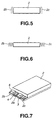
- each of the welded portions 2b and 2c When the width of each of the welded portions 2b and 2c is larger than the thickness of the battery, the welded portions 2b and 2c may be folded back, followed by folding the same, as shown in Fig. 5. When the thickness of the battery is very small, the welded portions 2b and 2c may be folded back plural times to form a bellows form, as shown in Fig. 6.
- the welded portions 2b and 2c are folded with a certain curvature. As compared with a structure that the welded portions 2b and 2c are folded with substantially no curvature, the sealing characteristic can be maintained if damage of the casing 2 constituted by the laminate film occurs in a case where the battery is dropped.
- the curvature radius is 0.025 mm or smaller, the effect of providing the curvature cannot easily be obtained. If the curvature radius is 1 mm or larger, a volume efficiency loss occurs excessively. It is preferable that the curvature radius is 0.05 mm to 0.5 mm. If the curvature radius is 0.05 mm or larger, the welded portions 2b and 2c can be folded by a machine. Therefore, a variety of methods can be used which include a method that a wire is sandwiched when folding is performed. When the welded portions 2b and 2c are folded with the curvature radius of 0.5 mm or larger, impact exerted from a planar direction cannot effectively be absorbed.
- the welded portions 2b and 2c can be folded toward the bottom, as shown in Figs. 7 and 8. Also the foregoing structure is included in the scope of the present invention. In the foregoing case, the volume efficiency somewhat deteriorates as described above.
- the size of the substrate for the control circuit 5 must be minimized to enable the control circuit 5 to be included in the terminal-portion sealing area. Therefore, it is preferable that a double-sided substrate is employed for the control circuit 5 and a land is formed on the reverse side of the substrate to establish the connection with the battery.
- the terminals of the battery may directly be soldered to the substrate of the control circuit 5, damage occurs if the welded portion 2a, which is the sealing portion of the battery, is heated. Therefore, the terminals are previously connected to the substrate of the control circuit 5. Moreover, the terminals are connected to each other by a means, such as resistance welding or ultrasonic welding, which does not exert excessive influence of heat. In the foregoing case, the foregoing damage can be prevented. Therefore, the terminals of the control circuit 5 may be structured such that individual terminal plates 6 are bonded to the control circuit 5 so as to be superimposed on the negative-electrode terminal lead 3 and the positive-electrode terminal lead 4.
- control circuit 5 may be formed on a printed circuit board 7 having terminals 8 formed thereon. Moreover, the printed circuit board 7 is folded back to superimpose the terminals 8 on the negative-electrode terminal lead 3 and the positive-electrode terminal lead 4.
- the terminals are folded.
- the stepped portions of the welded portions 2b and 2c can be used. Therefore, the overall thickness of the battery can be reduced.
- a polymer material for constituting the solid polymer electrolyte may be any one of the following materials: silicon gel, acrylic gel, acrylonitrile gel, polyphosphagen denatured polymer, polyethylene oxide, polypropylene oxide, their composite polymer, their crosslinked polymer or fluorine polymer which is, for example, poly (vinylidene fluoride), poly (vinylidene fluoride-co-hexafluoropropylene), poly (vinylidene fluoride-co-tetrafluoroethylene), poly (vinylidene fluoride-co-trifluoroethylene) and their mixture.
- the material is not limited to the foregoing materials.
- the solid electrolyte or the gel electrolyte laminated in the active material layer of the positive electrode or the active material layer of the negative electrode is obtained by causing the active material layer of the positive electrode or the active material layer of the negative electrode to be impregnated with solution composed of a polymer compound, an electrolyte salt and solvent (and a plasticizer in the case of the gel electrolyte). Then, the solvent is removed so that the solution is solidified.
- the active material layer of the positive electrode or the active material layer of the negative electrode is impregnated with a portion of the solid electrolyte or the gel electrolyte laminated in the active material layer of the positive electrode or the active material layer of the negative electrode so as to be solidified.
- the crosslinked material light or heat is used to crosslink the material so as to be solidified.
- the gel electrolyte is composed of a plasticizer containing a lithium salt and 2 wt% to 30 wt% matrix polymer. At this time, ester, ether or carbonate may be employed solely or a component of the plasticizer.
- a matrix polymer for gelling the carbonate may be any one of a variety of polymers for use to constitute the gel electrolyte. From a viewpoint of stability of oxidation and reduction, it is preferable that a fluorine polymer, such as poly (vinylidene fluoride) or poly (vinylidene fluoride-co-hexafluoropropylene), is employed.
- a fluorine polymer such as poly (vinylidene fluoride) or poly (vinylidene fluoride-co-hexafluoropropylene
- the solid polymer electrolyte is composed of a lithium salt and a polymer compound for dissolving the lithium salt.
- the polymer compound may be ether polymer, such as poly (ethylene oxide) or its crosslinked material, poly (methacrylate) ester, acrylate material, fluorine polymer, such as poly (vinylidene fluoride) or poly (vinylidene fluoride-co-hexafluoropropylene) may solely be employed or their mixture may be employed. From a viewpoint of stability of oxidation and reduction, it is preferable that a fluorine polymer, such as poly (vinylidene fluoride) or poly (vinylidene fluoride-co-hexafluoropropylene), is employed.
- the lithium salt which is contained in the gel electrolyte or the solid polymer electrolyte may be the lithium salt for use in a usual electrolytic solution for a battery.
- the lithium compound (salt) may be the following materials. Note that the present invention is not limited to the following materials.
- the lithium compound (salt) is exemplified by lithium chloride, lithium bromide, lithium iodide, lithium chlorate, lithium perchlorate, lithium bromate, lithium iodate, lithium nitrate, lithium tetrafluoroborate, lithium hexafluorophosphate, lithium acetate, bis (trifluoromethanesulfonyl) imide lithium.
- the foregoing lithium compound may solely be employed or a plurality of the lithium compounds may be mixed. From a viewpoint of stability of oxidation, it is preferable that LiPF 6 or LiBF 4 is employed.
- concentration of the lithium salt which must be dissolved will now be described.
- 0.1 mol to 3.0 mol may be dissolved in the plasticizer. It is preferable that the concentration is 0.5 mol/litter to 2.0 mol/litter.
- the battery according to the present invention may have a structure of a conventional lithium-ion battery except for the structure that the gel electrolyte or the solid electrolyte is employed.
- the material of the negative electrode of a lithium-ion battery may be a material which permits doping/dedoping of lithium.
- the material for constituting the negative electrode for example, non-graphitizing carbon or graphite may be employed.
- any one of the following materials may be employed: pyrocarbon, cokes (pitch cokes, needle cokes or petroleum cokes), graphite, vitreous carbon, a sintered material of organic polymer compound (material obtained by baking phenol resin or furan resin at a proper temperature so as to be carbonized), carbon fiber and active carbon.
- polymer such as polyacetylene or polypyrrole, or an oxide, such as SnO 2
- a known binder or the like may be added.
- the positive electrode may be constituted by using metal oxide, metal sulphide or specific polymer as the active material of the positive electrode.
- the active material of the positive electrode may be metal sulphide or oxide, such as TiS 2 , MoS 2 , NbSe 2 , or V 2 O 5 , which does not contain lithium, or lithium composite oxide mainly composed of LiMo 2 (where M is one or more types of transition metal, x varies depending on a state of charge/discharge and it is 0.05 or more and 1.10 or less).
- M is one or more types of transition metal, x varies depending on a state of charge/discharge and it is 0.05 or more and 1.10 or less.
- the transition metal M which constitutes the lithium composite oxide it is preferable that Co, Ni or Mn is employed.
- the lithium composite oxide is exemplified by LiCoO 2 , LiNiO 2 , LiNi y Co 1-y O 2 (where 0 ⁇ y ⁇ 1) and LiMn 2 O 4 .
- the foregoing lithium composite oxide is an excellent active material of the positive electrode which is capable of generating high voltage and which exhibits a satisfactory energy density.
- the positive electrode may be constituted by combining a plurality of types of the foregoing active materials of the positive electrode.
- a known conductive material and a binder may be added.
- the structure of the battery element 1 may be a laminate structure formed such that the positive electrodes and negative electrodes are alternately laminated in such a manner that the solid electrolyte is sandwiched, a winding-type structure formed such that the positive electrode and the negative electrode are laminated in such a manner that the solid electrolyte is sandwiched and the thus-formed laminate is wound and a folded structure formed such that the positive electrode and the negative electrode are laminated in such a manner that the solid electrolyte is sandwiched and the thus-formed laminate is alternately folded.
- the structure may arbitrarily be selected.
- the present invention may be applied to either of a primary battery or the secondary battery.
- a satisfactory effect can be obtained.
- Sample batteries were manufactured and evaluated by the following methods.
- the negative electrode was manufactured as follows.
- Powder of pulverized graphite in a quantity of 90 parts by weight and 10 parts by weight of poly (vinylidene fluoride-co-hexafluoropropylene) were mixed so that a mix for the negative electrode was prepared. Then, the foregoing mix was dispersed in N-methyl-2-pyrolidone so that slurry was prepared. The foregoing slurry was uniformly applied to either surface of an elongated copper foil which was a collector for the negative electrode and having a thickness of 10 ⁇ m. Then, the wet surface was dried, followed by compression-molding the elongated copper foil by a roll pressing machine. Thus, a negative electrode was manufactured.
- the positive electrode was manufactured as follows.
- LiCoO 2 lithium carbonate and cobalt carbonate were mixed at a ratio of 0.5 mol:1 mol, and then the mixed materials were baked at 900°C for 5 hours in air. Then, 91 parts by weight of obtained LiCoO 2 , 6 parts by weight of graphite serving as a conductive material and 10 parts by weight of poly (vinylidene fluoride-co-hexafluoropropylene) serving as the binder were mixed with one another. Thus, a mix for the positive electrode was prepared. Then, the mix was dispersed in N-methyl-2-pyrolidone so that slurry was prepared.
- the foregoing slurry was uniformly applied to either surface of an elongated aluminum foil which was a collector for the positive electrode and having a thickness of 20 ⁇ m. Then, the wet surface was dried, followed by compression-molding the elongated aluminum foil by a roll pressing machine. Thus, a positive electrode was manufactured.
- the gel electrolyte was obtained as follows.
- each of the negative and positive electrodes was uniformly coated with solution prepared by mixing and dissolving 10 parts by weight of poly (vinylidene fluoride-co-hexafluoropropylene) having a weight average molecular weight of 600,000 and 60 parts by weight of diethyl carbonate in 30 parts by weight of plasticizer composed of 42.5 parts by weight of ethylene carbonate (EC), 42.5 parts by weight of propylene carbonate (PC) and 15 parts by weight of LiPF 6 .
- plasticizer composed of 42.5 parts by weight of ethylene carbonate (EC), 42.5 parts by weight of propylene carbonate (PC) and 15 parts by weight of LiPF 6 .
- a positive-electrode-terminal, lead made of aluminum and a negative-electrode-terminal lead made of nickel were welded to the surface of the portion of the pole plate on which the active material was not applied. Then, the manufactured structure was encapsulated in a pack constitute by a laminate film. The pack was welded at 200°C for 10 seconds by a sealing machine so that test batteries were manufactured.
- the size of the control circuit of each sample was 32 mm ⁇ 5 mm ⁇ 3 mm.
- Sample 5 having the welded portions folded without any curvature was unsatisfactory in the impact resistance. Damage of the corner portions constituted by the laminate film resulted in introduction of water. Thus, significant difference was confirmed.
- Sample 6 having the bonded welded portions encountered an influence of the heat radiation characteristic which was exerted on the cycle characteristic.
- the nonaqueous electrolyte battery can be provided which exhibits a satisfactory volume energy density, the overall body of which including the control circuit has impact resistance, which has an improved heat radiating characteristic and elongated lifetime against charge/discharge cycles and which exhibits excellent producibility.
Landscapes
- Chemical & Material Sciences (AREA)
- Chemical Kinetics & Catalysis (AREA)
- Electrochemistry (AREA)
- General Chemical & Material Sciences (AREA)
- Engineering & Computer Science (AREA)
- Manufacturing & Machinery (AREA)
- Inorganic Chemistry (AREA)
- Microelectronics & Electronic Packaging (AREA)
- Materials Engineering (AREA)
- Secondary Cells (AREA)
- Sealing Battery Cases Or Jackets (AREA)
- Connection Of Batteries Or Terminals (AREA)
Abstract
Description
- The present invention relates to a nonaqueous electrolyte battery incorporating a casing constituted by a laminate film in which a battery element is accommodated. More particularly, the present invention relates to improvement in a volume energy density of a gel electrolyte battery, a solid electrolyte battery or the like.
- In recent years, a multiplicity of portable electronic apparatuses including camcoders, portable telephones and portable computers have come on the market. An attempt has been made to reduce the size and weight of the foregoing electronic apparatuses. As the portable power sources for the foregoing electronic apparatuses, batteries, in particular, secondary batteries, and more particularly, nonaqueous-electrolyte secondary batteries (so-called "lithium ion batteries") have energetically researched and developed to reduce the thickness of the battery and realize a foldable structure.
- As the electrolyte for the shape-variable battery, solidified electrolytic solution has energetically been studied. In particular, attention is being given to a polymer solid electrolyte lithium salt is dissolved in a gel electrolyte, which is a solid electrolyte containing a plasticizer, or a polymer.
- On the other hand, the merits of the foregoing battery, which are small thickness and light weight, are attempted to be used. Therefore, a variety of batteries have been studied which have an encapsulating structure which uses a plastic film or a laminate film constituted by bonding a plastic film and a metal sheet to each other.
- For example, a secondary battery must have a control circuit which controls charge/discharge and which is disposed in the vicinity of the battery. Therefore, a structure is required with which the volume efficiency can be improved if the foregoing charge/discharge circuit is mounted.
- Moreover, the battery having the above-mentioned structure must have a variety of characteristics as the battery investigated to cause the overall body of the battery including the control circuit to have impact resistance, improve the efficiency when the volume energy density is defined with the outer size of the battery constituted by the laminate film and improve heat radiating characteristic to elongate lifetime against charge/discharge cycles which is one of performance factors when the battery is operated.
- In view of the foregoing, an object of the present invention is to provide a nonaqueous electrolyte battery exhibiting an excellent volume efficiency even if a control circuit is mounted thereon.
- Another object of the present invention is to provide a nonaqueous electrolyte battery exhibiting excellent impact resistance and a heat radiating characteristic and having a long lifetime against charge/discharge cycles which is a performance factor when the battery is used.
- Another object of the present invention is to provide a nonaqueous electrolyte battery exhibiting excellent producibility.
- To achieve the foregoing objects, according to one aspect of the present invention, there is provided a nonaqueous electrolyte battery incorporating a casing constituted by a laminate film in which a battery element is accommodated and encapsulate by welding and electrode-terminal leads electrically conducted with electrodes are exposed to the outside portion of the casing such that the electrode-terminal leads are sandwiched by a welded portion, the nonaqueous electrolyte battery comprising: a control circuit for the nonaqueous electrolyte battery mounted on the welded portion of the casing.
- Since the control circuit of the battery is mounted on the welded portion, spaces in the battery in which the battery element is not present can effectively be used. As a result, the volume efficiency can considerably be improved.
- The basic concept of the present invention is as described above. Moreover, the present invention is structured to raise the volume energy density of the outer size of the battery including the control circuit for the battery. Thus, excellent impact resistance is attempted to be realized. Therefore, a portion of the welded portion except for the portion in which the electrode-terminal leads are sandwiched by the laminate film and which is welded is folded one or more times toward the side ends of the battery to have a width smaller than the thickness (the shortest length of the battery is defined to be a "thickness of the battery") of the battery. Thus, the size in the direction of the thickness of the battery is minimized. Thus, the foregoing folded portion protects the overall body of the battery including the battery.
- To improve the heat radiating characteristic, the portions folded toward the side ends of the battery are not bonded, that is, folded so as to enlarge the surface area.
- To improve impact resistance, the portions are folded toward the side ends of the battery with a curvature.
- Other objects, features and advantages of the invention will be evident from the following detailed description of the preferred embodiments described in conjunction with the attached drawings.
-
- Fig. 1 is a schematic perspective view showing an example of the structure of a nonaqueous electrolyte battery according to the present invention;
- Fig. 2 is a schematic cross sectional view showing an example of the structure of the nonaqueous electrolyte battery according to the present invention;
- Fig. 3 is a schematic perspective view showing a process for folding a welded portion;
- Fig. 4 is a schematic perspective view showing a process for folding electrode-terminal leads back;
- Fig. 5 is a schematic perspective view showing an example of a state in which the welded portion is folded;
- Fig. 6 is a schematic perspective view showing another example of a state in which the welded portion is folded;
- Fig. 7 is a schematic perspective view showing another example of the nonaqueous electrolyte battery according to the present invention;
- Fig. 8 is a schematic front view showing another example of the nonaqueous electrolyte battery according to the present invention; and
- Fig. 9 is an exploded perspective view showing an example of formed terminals in a control circuit.
-
- The structure of a nonaqueous electrolyte battery according to the present invention will now be described with reference to the drawings.
- The nonaqueous electrolyte battery (a so-called "lithium-ion secondary battery") according to the present invention is, for example, a solid electrolyte battery or a gel electrolyte battery. As shown in Figs. 1 and 2, a battery element 1 having a structure that a solid electrolyte or a gel electrolyte is placed between a positive-electrode active-material layer and a negative-electrode active-material layer is accommodated in a
casing 2 constituted by a laminate film. The peripheral portion of thecasing 2 is welded so that the battery element 1 is encapsulated. The nonaqueous electrolyte battery according to the present invention has a substantially rectangular shape. - The battery element 1 is provided with a negative-
electrode terminal lead 3 which is electrically connected to a negative electrode which constitutes the battery element 1 and a positive-electrode terminal lead 4 which is electrically connected to a positive electrode. The negative-electrode terminal lead 3 and the positive-electrode terminal lead 4 are drawn to the outside portion of thecasing 2. - The negative-
electrode terminal lead 3 and the positive-electrode terminal lead 4 are joined to collectors of the positive and negative electrodes. The positive-electrode terminal lead 4 must be made of a material, for example, aluminum, titanium or their alloy, which is not melted at a high potential. The negative-electrode terminal lead 3 may be made of copper, nickel or their alloy. - The lithium-ion secondary battery is formed into a battery which is a final produced when the body and the control circuit are packed in a decorative case.
- At this time, there is a requirement for effectively using a limited space to introduce many battery elements to raise the volume efficiency so as to improve the performance.
- The volume efficiency of a battery of a type having a structure that a flat battery is packed in a laminate film is greatly determined by a method of constituting the sealing portion. If the capacity of the battery is the same, reduction in the thickness is an important factor. In a case of a battery having a thickness of 3 mm, enlargement of a thickness of 100 µm results in deterioration in the volume efficiency by 3 %. Enlargement of the thickness by 100 µm of a battery having a thickness of 0.5 mm results in deterioration in the volume efficiency by 20 %.
- The direction in which the terminal leads are drawn will now be considered. A structure has been disclosed in, for example, Japanese Patent Laid-Open No. 10-208710, formed such that the terminal leads are drawn from a portion which is not the welded portion of the laminate film by using the surface of the collector of the battery element. When the connection with the control circuit is considered, the electric line connected to the control circuit is present in the direction of the thickness of the battery. Therefore, the volume efficiency of the battery undesirably deteriorates after the body of the battery and the control circuit are packed in the decorative case and thus a final product is manufactured.
- Therefore, the
welded portion 2a of the laminate film holds the negative-electrode terminal lead 3 and the positive-electrode terminal lead 4, as shown in Figs. 1 and 2. Thus, the negative-electrode terminal lead 3 and the positive-electrode terminal lead 4 are drawn from thewelded portion 2a. - The
control circuit 5 is mounted on a space in which the battery element 1 is not present. Thus, the battery element 1 and thecontrol circuit 5 are electrically connected to each other. Moreover, thecontrol circuit 5 is held on the weldedportion 2a of thecasing 2 so as to be stable against vibrations and a shock. - When a space capable of accommodating the battery element 1 is previously provided for the
casing 2 by, for example, deep drawing, the space on which thecontrol circuit 5 is mounted can effectively be created. As a result, the space can furthermore effectively be used. - The welded portion of the
casing 2 in a direction except for the direction from which the terminal leads are drawn will now be described. Weldedportions portion 2a from which the terminal leads are drawn are folded one or more times in such a manner that the width is not larger than the thickness of the battery. The weldedportions portions control circuit 5. - The welded
portions - The folded welded
portions control circuit 5 from the side surfaces from an external impact. The foregoing structure permits a battery exhibiting a high volume energy density of the overall size of the battery including the control circuit and satisfactory impact resistance to be obtained. - The basic structure of the nonaqueous electrolyte battery according to the present invention is formed as described above. To specifically describe the structure of the nonaqueous electrolyte battery according to the present invention, a procedure for mounting the
control circuit 5 is shown in Figs. 3 and 4. - To mount the
control circuit 5, the weldedportions electrode terminal lead 3 and the positive-electrode terminal lead 4 are folded back onto the weldedportion 2a. Then, thecontrol circuit 5 is secured to the upper surfaces of the negative-electrode terminal lead 3 and positive-electrode terminal lead 4. Thus, thecontrol circuit 5 and the positive and negative terminal leads 3 and 4 are electrically connected to one another. Therefore, the above-mentioned battery structure can be obtained. - The battery having the above-mentioned structure is accommodated in a case, for example, a decorative case so that a final product is formed. When a
connection terminal 5a of thecontrol circuit 5 is exposed to the outside through an opening provided for the container, the connection to an external circuit is permitted. - It is preferable that the welded
portions casing 2 is used to maintain the state of folding. As a result, a battery having a large surface area, exhibiting excellent a heat radiating characteristic and satisfactory cycle characteristic can be obtained. - When the width of each of the welded
portions portions portions - It is preferable that the welded
portions portions casing 2 constituted by the laminate film occurs in a case where the battery is dropped. - If the curvature radius is 0.025 mm or smaller, the effect of providing the curvature cannot easily be obtained. If the curvature radius is 1 mm or larger, a volume efficiency loss occurs excessively. It is preferable that the curvature radius is 0.05 mm to 0.5 mm. If the curvature radius is 0.05 mm or larger, the welded
portions portions - The welded
portions - In the foregoing case, the size of the substrate for the
control circuit 5 must be minimized to enable thecontrol circuit 5 to be included in the terminal-portion sealing area. Therefore, it is preferable that a double-sided substrate is employed for thecontrol circuit 5 and a land is formed on the reverse side of the substrate to establish the connection with the battery. - Although the terminals of the battery may directly be soldered to the substrate of the
control circuit 5, damage occurs if the weldedportion 2a, which is the sealing portion of the battery, is heated. Therefore, the terminals are previously connected to the substrate of thecontrol circuit 5. Moreover, the terminals are connected to each other by a means, such as resistance welding or ultrasonic welding, which does not exert excessive influence of heat. In the foregoing case, the foregoing damage can be prevented. Therefore, the terminals of thecontrol circuit 5 may be structured such thatindividual terminal plates 6 are bonded to thecontrol circuit 5 so as to be superimposed on the negative-electrode terminal lead 3 and the positive-electrode terminal lead 4. As an alternative to this, thecontrol circuit 5 may be formed on a printedcircuit board 7 havingterminals 8 formed thereon. Moreover, the printedcircuit board 7 is folded back to superimpose theterminals 8 on the negative-electrode terminal lead 3 and the positive-electrode terminal lead 4. - Since the foregoing terminals result in enlargement of the size of the battery if not contrivance is employed, it is preferable that the terminals are folded. When the terminals are folded back to the bottom surface, the stepped portions of the welded
portions - When a solid electrolyte battery or a gel electrolyte battery is manufactured which incorporates the battery element 1, a polymer material for constituting the solid polymer electrolyte may be any one of the following materials: silicon gel, acrylic gel, acrylonitrile gel, polyphosphagen denatured polymer, polyethylene oxide, polypropylene oxide, their composite polymer, their crosslinked polymer or fluorine polymer which is, for example, poly (vinylidene fluoride), poly (vinylidene fluoride-co-hexafluoropropylene), poly (vinylidene fluoride-co-tetrafluoroethylene), poly (vinylidene fluoride-co-trifluoroethylene) and their mixture. As a matter of course, the material is not limited to the foregoing materials.
- The solid electrolyte or the gel electrolyte laminated in the active material layer of the positive electrode or the active material layer of the negative electrode is obtained by causing the active material layer of the positive electrode or the active material layer of the negative electrode to be impregnated with solution composed of a polymer compound, an electrolyte salt and solvent (and a plasticizer in the case of the gel electrolyte). Then, the solvent is removed so that the solution is solidified. The active material layer of the positive electrode or the active material layer of the negative electrode is impregnated with a portion of the solid electrolyte or the gel electrolyte laminated in the active material layer of the positive electrode or the active material layer of the negative electrode so as to be solidified. In the case of the crosslinked material, light or heat is used to crosslink the material so as to be solidified.
- The gel electrolyte is composed of a plasticizer containing a lithium salt and 2 wt% to 30 wt% matrix polymer. At this time, ester, ether or carbonate may be employed solely or a component of the plasticizer.
- When the gel electrolyte is prepared, a matrix polymer for gelling the carbonate may be any one of a variety of polymers for use to constitute the gel electrolyte. From a viewpoint of stability of oxidation and reduction, it is preferable that a fluorine polymer, such as poly (vinylidene fluoride) or poly (vinylidene fluoride-co-hexafluoropropylene), is employed.
- The solid polymer electrolyte is composed of a lithium salt and a polymer compound for dissolving the lithium salt. The polymer compound may be ether polymer, such as poly (ethylene oxide) or its crosslinked material, poly (methacrylate) ester, acrylate material, fluorine polymer, such as poly (vinylidene fluoride) or poly (vinylidene fluoride-co-hexafluoropropylene) may solely be employed or their mixture may be employed. From a viewpoint of stability of oxidation and reduction, it is preferable that a fluorine polymer, such as poly (vinylidene fluoride) or poly (vinylidene fluoride-co-hexafluoropropylene), is employed.
- The lithium salt which is contained in the gel electrolyte or the solid polymer electrolyte may be the lithium salt for use in a usual electrolytic solution for a battery. The lithium compound (salt) may be the following materials. Note that the present invention is not limited to the following materials.
- The lithium compound (salt) is exemplified by lithium chloride, lithium bromide, lithium iodide, lithium chlorate, lithium perchlorate, lithium bromate, lithium iodate, lithium nitrate, lithium tetrafluoroborate, lithium hexafluorophosphate, lithium acetate, bis (trifluoromethanesulfonyl) imide lithium. LiAsF6, LiCF3SO3, LiC (SO2CF3)3, LiAlCl4 and LiSiF6.
- The foregoing lithium compound may solely be employed or a plurality of the lithium compounds may be mixed. From a viewpoint of stability of oxidation, it is preferable that LiPF6 or LiBF4 is employed.
- The concentration of the lithium salt which must be dissolved will now be described. In the case of the gel electrolyte, 0.1 mol to 3.0 mol may be dissolved in the plasticizer. It is preferable that the concentration is 0.5 mol/litter to 2.0 mol/litter.
- The battery according to the present invention may have a structure of a conventional lithium-ion battery except for the structure that the gel electrolyte or the solid electrolyte is employed.
- That is, the material of the negative electrode of a lithium-ion battery may be a material which permits doping/dedoping of lithium. The material for constituting the negative electrode, for example, non-graphitizing carbon or graphite may be employed. Specifically, any one of the following materials may be employed: pyrocarbon, cokes (pitch cokes, needle cokes or petroleum cokes), graphite, vitreous carbon, a sintered material of organic polymer compound (material obtained by baking phenol resin or furan resin at a proper temperature so as to be carbonized), carbon fiber and active carbon. As the material which permits doping/dedoping lithium, polymer, such as polyacetylene or polypyrrole, or an oxide, such as SnO2, may be employed. When the negative electrode is constituted from the foregoing material, a known binder or the like may be added.
- The positive electrode may be constituted by using metal oxide, metal sulphide or specific polymer as the active material of the positive electrode. When a lithium battery is constituted, the active material of the positive electrode may be metal sulphide or oxide, such as TiS2, MoS2, NbSe2, or V2O5, which does not contain lithium, or lithium composite oxide mainly composed of LiMo2 (where M is one or more types of transition metal, x varies depending on a state of charge/discharge and it is 0.05 or more and 1.10 or less). As the transition metal M which constitutes the lithium composite oxide, it is preferable that Co, Ni or Mn is employed. The lithium composite oxide is exemplified by LiCoO2, LiNiO2, LiNiyCo1-yO2 (where 0 < y < 1) and LiMn2O4. The foregoing lithium composite oxide is an excellent active material of the positive electrode which is capable of generating high voltage and which exhibits a satisfactory energy density. The positive electrode may be constituted by combining a plurality of types of the foregoing active materials of the positive electrode. When the positive electrode is constituted by using the foregoing active material of the positive electrode, a known conductive material and a binder may be added.
- The structure of the battery element 1 may be a laminate structure formed such that the positive electrodes and negative electrodes are alternately laminated in such a manner that the solid electrolyte is sandwiched, a winding-type structure formed such that the positive electrode and the negative electrode are laminated in such a manner that the solid electrolyte is sandwiched and the thus-formed laminate is wound and a folded structure formed such that the positive electrode and the negative electrode are laminated in such a manner that the solid electrolyte is sandwiched and the thus-formed laminate is alternately folded. The structure may arbitrarily be selected.
- The present invention may be applied to either of a primary battery or the secondary battery. When the present invention is applied to a nonaqueous-electrolyte secondary battery, a satisfactory effect can be obtained.
- Examples and comparative examples of the present invention will now be described in accordance with results of experiments.
- Sample batteries were manufactured and evaluated by the following methods.
- Initially, the negative electrode was manufactured as follows.
- Powder of pulverized graphite in a quantity of 90 parts by weight and 10 parts by weight of poly (vinylidene fluoride-co-hexafluoropropylene) were mixed so that a mix for the negative electrode was prepared. Then, the foregoing mix was dispersed in N-methyl-2-pyrolidone so that slurry was prepared. The foregoing slurry was uniformly applied to either surface of an elongated copper foil which was a collector for the negative electrode and having a thickness of 10 µm. Then, the wet surface was dried, followed by compression-molding the elongated copper foil by a roll pressing machine. Thus, a negative electrode was manufactured.
- On the other hand, the positive electrode was manufactured as follows.
- To obtain an active material (LiCoO2) for the positive electrode, lithium carbonate and cobalt carbonate were mixed at a ratio of 0.5 mol:1 mol, and then the mixed materials were baked at 900°C for 5 hours in air. Then, 91 parts by weight of obtained LiCoO2, 6 parts by weight of graphite serving as a conductive material and 10 parts by weight of poly (vinylidene fluoride-co-hexafluoropropylene) serving as the binder were mixed with one another. Thus, a mix for the positive electrode was prepared. Then, the mix was dispersed in N-methyl-2-pyrolidone so that slurry was prepared. The foregoing slurry was uniformly applied to either surface of an elongated aluminum foil which was a collector for the positive electrode and having a thickness of 20 µm. Then, the wet surface was dried, followed by compression-molding the elongated aluminum foil by a roll pressing machine. Thus, a positive electrode was manufactured.
- Moreover, the gel electrolyte was obtained as follows.
- The surface of each of the negative and positive electrodes was uniformly coated with solution prepared by mixing and dissolving 10 parts by weight of poly (vinylidene fluoride-co-hexafluoropropylene) having a weight average molecular weight of 600,000 and 60 parts by weight of diethyl carbonate in 30 parts by weight of plasticizer composed of 42.5 parts by weight of ethylene carbonate (EC), 42.5 parts by weight of propylene carbonate (PC) and 15 parts by weight of LiPF6. Thus, the negative electrode and the positive electrode were impregnated with the solution, and then negative electrode and the positive electrode were allowed to stand at room temperature for 8 hours. Thus, dimethyl carbonate was vaporized and removed so that the gel electrolyte was obtained.
- The gel electrolyte sides of the negative electrode and the positive electrode were joined and contact-bonded. Thus, 3.3 cm × 5.2 cm flat gel-electrolyte battery having a thickness of 0.3 mm and a capacity of 50 mAh and 3.3 cm × 5.2 cm flat gel-electrolyte battery having a thickness of 3.3 mm and a capacity of 550 mAh were manufactured.
- A positive-electrode-terminal, lead made of aluminum and a negative-electrode-terminal lead made of nickel were welded to the surface of the portion of the pole plate on which the active material was not applied. Then, the manufactured structure was encapsulated in a pack constitute by a laminate film. The pack was welded at 200°C for 10 seconds by a sealing machine so that test batteries were manufactured.
- The structure of each sample was as follows.
- Sample 1: the welded
portions - Sample 2: the welded
portions - Sample 3: the welded
portions - Sample 4: the welded
portions - Sample 5: the structure of the battery was similar to that of Sample 1. When
the welded
portions - Sample 6: the structure of the battery was similar to that of Sample 1. The
folded welded
portions - Sample 7: the welded
portions - Sample 8: the welded
portions - Sample 9: the casing was not deep-drawn. The other structures were similar to Sample 1. The length in the direction of 3.3 cm was 3.4 cm. The thickness was 35 mm. When the control circuit was included, the corresponding portion projected. Thus, the thickness was 5 mm.
- Sample 10: the control circuit was not mounted on the welded
portion 2a. As an alternative to this, the control was joined to outwards project over the terminal lead. -
- The size of the control circuit of each sample was 32 mm × 5 mm × 3 mm.
- The structural characteristics of the samples were shown in Table 1.


- The samples were evaluated as follows.
- 1. Each sample was initially discharged at a 5-hour ratio (1/5C) of the theoretical capacity. Then, the battery was charged at a 2-hour ratio (1/2C) of the theoretical capacity. The capacity realized after the discharge and an average discharging voltage were used to calculate the volume energy density in accordance with the volume of a rectangular parallelopiped of the structure which was packed in the laminate film and on which the control was mounted.
- 2. Each sample was subjected to a charge/discharge cycle test 500 times at the two-hour discharge (1/2C) of the theoretical capacity at 50°C. Thus, a retention ratio of the discharge capacity was measured.
- 3. Each sample was subjected to a 2 m in height drop test 50 times. Then, the sample was placed in a constant-temperature and humidity tank, the temperature of which was 70°C and the relative humidity of which was 90 %. After a lapse of 720 hours, measurement of water was performed by a Karl Fischer's method.
-
- Results were shown in Table 2.
Volume Energy Density (Wh/l) Discharge Capacity Retention Ratio (%) Concentration of Water (ppm) Sample 1 280 92 3 Sample 2280 90 3 Sample 3159 93 2 Sample 4163 90 5 Sample 5280 90 12 Sample 6280 80 5 Sample 7130 90 3 Sample 8271 89 2 Sample 9 208 91 3 Sample 10 263 92 2 - As can be understood from Table 2, Sample 1 to 4 each having the welded portions folded toward the side ends of the battery with the curvature had excellent volume energy densities. Also satisfactory impact resistance was realized. In addition, introduction of water was satisfactorily prevented. As a result, excellent cycle characteristics of the foregoing samples were confirmed.
- On the other hand,
Sample 5 having the welded portions folded without any curvature was unsatisfactory in the impact resistance. Damage of the corner portions constituted by the laminate film resulted in introduction of water. Thus, significant difference was confirmed. -
Sample 6 having the bonded welded portions encountered an influence of the heat radiation characteristic which was exerted on the cycle characteristic. - When
Samples 1 and 2 and thesample 7 were compared and whenSamples Sample 6 were compared, an effect on the volume energy density was confirmed in a case where the welded portions except for the portion in which the electrode terminal leads were sandwiched by the laminate film so as to be welded were folded toward the side ends of the battery in such a manner that the width was smaller than the thickness of the battery. - When a comparison was made between
Sample 1 and 2 and samples 9 and 10, an effect was confirmed in a case where the laminate film was employed in which the space was formed accommodate the battery and the control circuit was mounted on the space created in the terminal portion. - As can be understood from the description, according to the present invention, the nonaqueous electrolyte battery can be provided which exhibits a satisfactory volume energy density, the overall body of which including the control circuit has impact resistance, which has an improved heat radiating characteristic and elongated lifetime against charge/discharge cycles and which exhibits excellent producibility.
- Although the invention has been described in its preferred form and structure with a certain degree of particularity, it is understood that the present disclosure of the preferred form can be changed in the details of construction and in the combination and arrangement of parts without departing from the spirit and the scope or the invention as hereinafter claimed.
Claims (18)
- A nonaqueous electrolyte battery incorporating a casing constituted by a laminate film in which a battery element is accommodated and encapsulate by welding and electrode-terminal leads electrically conducted with electrodes are exposed to the outside portion of said casing such that said electrode-terminal leads are sandwiched by a welded portion, said nonaqueous electrolyte battery comprising:a control circuit for said nonaqueous electrolyte battery mounted on said welded portion of said casing.
- A nonaqueous electrolyte battery according to claim 1, wherein said casing is deep-drawn to create a space for accommodating said battery element.
- A nonaqueous electrolyte battery according to claim 1, wherein the outer shape is rectangular, and said control circuit is mounted on said welded portion corresponding to one of four sides from which said electrode terminal leads are drawn.
- A nonaqueous electrolyte battery according to claim 3, wherein said welded portion corresponding to the other sides is folded to have a width smaller than the thickness of said battery so as to be folded back along the side surface of said casing.
- A nonaqueous electrolyte battery according to claim 4, wherein the other sides are two sides perpendicular to the side from which said electrode-terminal leads are drawn.
- A nonaqueous electrolyte battery according to claim 5, wherein two end portions of said welded portion on which said control circuit is mounted by folding is raised to create a space for accommodating said control circuit.
- A nonaqueous electrolyte battery according to claim 4, wherein said welded portion corresponding to the other side maintains the folded state by plastic deformation of said casing.
- A nonaqueous electrolyte battery according to claim 4, wherein said welded portion corresponding to the other side is folded with a curvature.
- A nonaqueous electrolyte battery according to claim 8, wherein the curvature of said welded portion corresponding to the other side is 0.05 mm to 0.5 mm.
- A nonaqueous electrolyte battery according to claim 8, wherein said welded portion corresponding to the other side is folded through a wire.
- A nonaqueous electrolyte battery according to claim 3, wherein said electrode-terminal lead is folded back toward said welded portion so as to be connected to said control circuit.
- A nonaqueous electrolyte battery according to claim 3, wherein said control circuit is formed on a flexible printed circuit board, and a terminal portion provided for said flexible printed board is connected to said electrode-terminal lead.
- A nonaqueous electrolyte battery according to claim 1, wherein an electrolyte constituting said battery element is a gel electrolyte or a solid electrolyte containing matrix polymer and a lithium salt.
- A nonaqueous electrolyte battery according to claim 1, wherein a negative electrode constituting said battery element is a negative electrode containing a material which is capable of doping/dedoping lithium.
- A nonaqueous electrolyte battery according to claim 13, wherein said material which is capable of doping/dedoping lithium is a carbon material.
- A nonaqueous electrolyte battery according to claim 1, a positive electrode constituting said battery element is a positive electrode containing a composite oxide of lithium and transition metal.
- A nonaqueous electrolyte battery according to claim 1, said nonaqueous electrolyte battery is a secondary battery.
- A nonaqueous electrolyte battery according to claim 1, wherein said battery element is accommodated in a container together with said control circuit, and a terminal of said control circuit is exposed to the outside through an opening formed in said container.
Applications Claiming Priority (2)
| Application Number | Priority Date | Filing Date | Title |
|---|---|---|---|
| JP32851298A JP3899499B2 (en) | 1998-11-18 | 1998-11-18 | Non-aqueous electrolyte battery |
| JP32851298 | 1998-11-18 |
Publications (2)
| Publication Number | Publication Date |
|---|---|
| EP1003233A1 true EP1003233A1 (en) | 2000-05-24 |
| EP1003233B1 EP1003233B1 (en) | 2005-01-12 |
Family
ID=18211117
Family Applications (1)
| Application Number | Title | Priority Date | Filing Date |
|---|---|---|---|
| EP99122700A Expired - Lifetime EP1003233B1 (en) | 1998-11-18 | 1999-11-15 | Nonaqueous electrolyte battery |
Country Status (7)
| Country | Link |
|---|---|
| US (1) | US6368744B1 (en) |
| EP (1) | EP1003233B1 (en) |
| JP (1) | JP3899499B2 (en) |
| KR (1) | KR100648550B1 (en) |
| CN (1) | CN1147958C (en) |
| DE (1) | DE69923148T2 (en) |
| TW (1) | TW444420B (en) |
Cited By (5)
| Publication number | Priority date | Publication date | Assignee | Title |
|---|---|---|---|---|
| EP1134832A2 (en) | 2000-03-17 | 2001-09-19 | Sony Corporation | Method of manufacturing a battery |
| WO2001099210A1 (en) * | 2000-06-22 | 2001-12-27 | Danionics A/S | Electrochemical cells |
| EP1139482A3 (en) * | 2000-03-29 | 2003-08-06 | VARTA Microbattery GmbH | Electric accumulator with electronic protection circuit |
| EP1239531A3 (en) * | 2001-03-07 | 2006-03-15 | Nisshinbo Industries Inc. | Pregel compositions for polymer gel electrolytes, method of dehydrating pregel compositions, secondary cell, and electrical double-layer capacitor |
| EP1717881A1 (en) * | 2005-04-26 | 2006-11-02 | Samsung SDI Co., Ltd. | Polymer battery pack and manufacturing method of the same |
Families Citing this family (48)
| Publication number | Priority date | Publication date | Assignee | Title |
|---|---|---|---|---|
| JP4793517B2 (en) * | 2000-07-10 | 2011-10-12 | 株式会社Gsユアサ | Sealed battery |
| JP4686823B2 (en) * | 2000-07-10 | 2011-05-25 | 株式会社Gsユアサ | Sealed battery |
| JP2003142043A (en) | 2001-07-09 | 2003-05-16 | Hitachi Maxell Ltd | Battery |
| KR100958647B1 (en) | 2002-12-18 | 2010-05-20 | 삼성에스디아이 주식회사 | Pouch Type Secondary Battery Unit |
| US7348762B2 (en) | 2003-05-01 | 2008-03-25 | Sony Corporation | Battery pack and method for producing battery pack |
| KR100553200B1 (en) * | 2003-06-19 | 2006-02-22 | 삼성에스디아이 주식회사 | Battery pack |
| JP4788889B2 (en) | 2003-10-07 | 2011-10-05 | 日本電気株式会社 | Film-clad battery and method for producing film-clad battery |
| KR100553753B1 (en) * | 2003-10-16 | 2006-02-20 | 삼성에스디아이 주식회사 | Pouch Type Secondary Battery |
| KR100561284B1 (en) * | 2003-12-26 | 2006-03-15 | 삼성에스디아이 주식회사 | Pouch Type Lithium Secondary Battery |
| CN2772044Y (en) * | 2004-11-18 | 2006-04-12 | 比亚迪股份有限公司 | Lithium ion secondary cell |
| USD516018S1 (en) * | 2005-01-28 | 2006-02-28 | Casio Keisanki Kabushiki Kaisha | Rechargeable battery for digital camera |
| US20070044299A1 (en) * | 2005-08-30 | 2007-03-01 | Cheng-Hsin Chen | Method of fabricating rechargeable batteries |
| KR100760752B1 (en) * | 2005-12-23 | 2007-09-21 | 삼성에스디아이 주식회사 | Lithium Polymer Battery and Manufacturing Method Thereof |
| USD571717S1 (en) * | 2006-01-24 | 2008-06-24 | Symbol Technologies, Inc. | Mobile device battery |
| KR100763931B1 (en) * | 2006-06-27 | 2007-10-05 | (주)비피에스 | Manufacturing Method of Battery Using Heat Shrinkable Tube as Appearance |
| JP4165586B2 (en) | 2006-08-02 | 2008-10-15 | ソニー株式会社 | Battery pack |
| KR100913836B1 (en) * | 2006-09-18 | 2009-08-26 | 주식회사 엘지화학 | Pouch type secondary battery with improved safety |
| JP4992921B2 (en) | 2009-02-19 | 2012-08-08 | ソニー株式会社 | Non-aqueous electrolyte secondary battery |
| WO2012047316A1 (en) * | 2010-05-21 | 2012-04-12 | Ada Technologies, Inc. | High performance carbon nano-tube composites for electrochemical energy storage devices |
| JP5035397B2 (en) | 2010-07-28 | 2012-09-26 | Tdk株式会社 | Electrochemical devices |
| WO2012147375A1 (en) * | 2011-04-27 | 2012-11-01 | 日立マクセルエナジー株式会社 | Battery unit |
| KR20130016034A (en) * | 2011-08-04 | 2013-02-14 | 주식회사 엘지화학 | Secondary battery pack with improved safety |
| KR20130016035A (en) | 2011-08-04 | 2013-02-14 | 주식회사 엘지화학 | Secondary battery pack of novel structure |
| KR20130018097A (en) * | 2011-08-12 | 2013-02-20 | 주식회사 엘지화학 | Secondary battery pack of novel structure |
| US9343716B2 (en) | 2011-12-29 | 2016-05-17 | Apple Inc. | Flexible battery pack |
| TWI484881B (en) * | 2011-12-30 | 2015-05-11 | Uer Technology Corp | Welding structure and welding method for connecting lithium battery to electric circuit board |
| WO2013105231A1 (en) | 2012-01-11 | 2013-07-18 | 日立マクセル株式会社 | Battery unit |
| US9812680B2 (en) | 2012-08-30 | 2017-11-07 | Apple Inc. | Low Z-fold battery seal |
| US20140147703A1 (en) * | 2012-11-28 | 2014-05-29 | Apple Inc. | Battery safety circuit and tab placement and orientation |
| KR20140145787A (en) * | 2013-06-14 | 2014-12-24 | 삼성에스디아이 주식회사 | Rechargeable battery pack |
| US9799933B2 (en) * | 2013-08-28 | 2017-10-24 | Robert Bosch Gmbh | Solid state battery with integrated rate booster |
| KR101619926B1 (en) * | 2013-09-27 | 2016-05-12 | 주식회사 엘지화학 | Battery Pack Having PCM Case |
| US9593969B2 (en) | 2013-12-27 | 2017-03-14 | Apple Inc. | Concealed electrical connectors |
| US9479007B1 (en) | 2014-02-21 | 2016-10-25 | Apple Inc. | Induction charging system |
| US20150255776A1 (en) | 2014-03-06 | 2015-09-10 | Apple Inc. | Battery Pack System |
| US9455582B2 (en) | 2014-03-07 | 2016-09-27 | Apple Inc. | Electronic device and charging device for electronic device |
| US9917335B2 (en) | 2014-08-28 | 2018-03-13 | Apple Inc. | Methods for determining and controlling battery expansion |
| KR102290162B1 (en) * | 2015-01-19 | 2021-08-17 | 주식회사 아모그린텍 | Flexible battery and supplementary battery including the same |
| US10637017B2 (en) | 2016-09-23 | 2020-04-28 | Apple Inc. | Flexible battery structure |
| KR102247395B1 (en) | 2016-10-05 | 2021-05-03 | 삼성에스디아이 주식회사 | Rechargeable battery |
| JP6762194B2 (en) * | 2016-10-11 | 2020-09-30 | 株式会社やまびこ | Backpack type power supply system |
| WO2018100846A1 (en) * | 2016-11-29 | 2018-06-07 | 株式会社村田製作所 | Secondary battery and device |
| JP6683263B2 (en) * | 2016-11-29 | 2020-04-15 | 株式会社村田製作所 | Secondary battery |
| CN110121804B (en) * | 2016-12-29 | 2022-12-02 | 株式会社村田制作所 | Negative electrode active material, manufacturing method thereof, negative electrode, battery, battery pack, electronic equipment, and power storage device |
| US20210020880A1 (en) * | 2018-03-28 | 2021-01-21 | Honda Motor Co., Ltd. | Solid-state battery module |
| JP7224903B2 (en) * | 2018-12-26 | 2023-02-20 | 株式会社東芝 | BATTERY, BATTERY ASSEMBLY AND BATTERY MODULE |
| CN114444643B (en) | 2019-04-17 | 2024-08-06 | 苹果公司 | Wireless locatable tags |
| WO2026053768A1 (en) * | 2024-09-03 | 2026-03-12 | 日東電工株式会社 | Inter-cell structure |
Citations (8)
| Publication number | Priority date | Publication date | Assignee | Title |
|---|---|---|---|---|
| EP0390557A2 (en) * | 1989-03-30 | 1990-10-03 | Mhb Joint Venture | Battery assembly and method for producing the same |
| EP0644642A2 (en) * | 1993-07-30 | 1995-03-22 | Texas Instruments Incorporated | Improvements in or relating to power sources |
| US5436089A (en) * | 1993-08-31 | 1995-07-25 | Vst Power Systems, Inc. | Portable battery pack apparatus and method of fabrication thereof |
| JPH07201358A (en) * | 1993-12-29 | 1995-08-04 | Sony Corp | Non-aqueous electrolyte secondary battery |
| JPH09139235A (en) * | 1995-11-16 | 1997-05-27 | Japan Storage Battery Co Ltd | Battery device |
| EP0862230A2 (en) * | 1997-02-24 | 1998-09-02 | Mitsubishi Denki Kabushiki Kaisha | Thin battery |
| EP0863564A1 (en) * | 1997-02-18 | 1998-09-09 | Koninklijke Philips Electronics N.V. | Thin type accumulator device comprising an electrochemical cell and electrical contact means |
| EP0917218A2 (en) * | 1997-11-05 | 1999-05-19 | Philips Consumer Communications France | A battery unit and a portable battery-operated device including such a battery unit |
Family Cites Families (4)
| Publication number | Priority date | Publication date | Assignee | Title |
|---|---|---|---|---|
| JP3485655B2 (en) * | 1994-12-14 | 2004-01-13 | 株式会社ルネサステクノロジ | Composite MOSFET |
| JPH10241736A (en) * | 1997-02-26 | 1998-09-11 | Rohm Co Ltd | Battery structure |
| US5895731A (en) * | 1997-05-15 | 1999-04-20 | Nelson E. Smith | Thin-film lithium battery and process |
| KR100863564B1 (en) * | 2008-03-26 | 2008-10-15 | 주식회사 텔론텍 | Cancer device |
-
1998
- 1998-11-18 JP JP32851298A patent/JP3899499B2/en not_active Expired - Lifetime
-
1999
- 1999-11-11 TW TW088119704A patent/TW444420B/en not_active IP Right Cessation
- 1999-11-15 DE DE69923148T patent/DE69923148T2/en not_active Expired - Lifetime
- 1999-11-15 EP EP99122700A patent/EP1003233B1/en not_active Expired - Lifetime
- 1999-11-16 US US09/440,537 patent/US6368744B1/en not_active Expired - Lifetime
- 1999-11-17 KR KR1019990051002A patent/KR100648550B1/en not_active Expired - Lifetime
- 1999-11-18 CN CNB991273486A patent/CN1147958C/en not_active Expired - Lifetime
Patent Citations (8)
| Publication number | Priority date | Publication date | Assignee | Title |
|---|---|---|---|---|
| EP0390557A2 (en) * | 1989-03-30 | 1990-10-03 | Mhb Joint Venture | Battery assembly and method for producing the same |
| EP0644642A2 (en) * | 1993-07-30 | 1995-03-22 | Texas Instruments Incorporated | Improvements in or relating to power sources |
| US5436089A (en) * | 1993-08-31 | 1995-07-25 | Vst Power Systems, Inc. | Portable battery pack apparatus and method of fabrication thereof |
| JPH07201358A (en) * | 1993-12-29 | 1995-08-04 | Sony Corp | Non-aqueous electrolyte secondary battery |
| JPH09139235A (en) * | 1995-11-16 | 1997-05-27 | Japan Storage Battery Co Ltd | Battery device |
| EP0863564A1 (en) * | 1997-02-18 | 1998-09-09 | Koninklijke Philips Electronics N.V. | Thin type accumulator device comprising an electrochemical cell and electrical contact means |
| EP0862230A2 (en) * | 1997-02-24 | 1998-09-02 | Mitsubishi Denki Kabushiki Kaisha | Thin battery |
| EP0917218A2 (en) * | 1997-11-05 | 1999-05-19 | Philips Consumer Communications France | A battery unit and a portable battery-operated device including such a battery unit |
Non-Patent Citations (2)
| Title |
|---|
| PATENT ABSTRACTS OF JAPAN vol. 1995, no. 11 26 December 1995 (1995-12-26) * |
| PATENT ABSTRACTS OF JAPAN vol. 1997, no. 09 30 September 1997 (1997-09-30) * |
Cited By (8)
| Publication number | Priority date | Publication date | Assignee | Title |
|---|---|---|---|---|
| EP1134832A2 (en) | 2000-03-17 | 2001-09-19 | Sony Corporation | Method of manufacturing a battery |
| EP1134832A3 (en) * | 2000-03-17 | 2006-08-16 | Sony Corporation | Method of manufacturing a battery |
| EP1139482A3 (en) * | 2000-03-29 | 2003-08-06 | VARTA Microbattery GmbH | Electric accumulator with electronic protection circuit |
| WO2001099210A1 (en) * | 2000-06-22 | 2001-12-27 | Danionics A/S | Electrochemical cells |
| GB2380614A (en) * | 2000-06-22 | 2003-04-09 | Danionics As | Electrochemical cells |
| GB2380614B (en) * | 2000-06-22 | 2003-11-12 | Danionics As | Electrochemical cells |
| EP1239531A3 (en) * | 2001-03-07 | 2006-03-15 | Nisshinbo Industries Inc. | Pregel compositions for polymer gel electrolytes, method of dehydrating pregel compositions, secondary cell, and electrical double-layer capacitor |
| EP1717881A1 (en) * | 2005-04-26 | 2006-11-02 | Samsung SDI Co., Ltd. | Polymer battery pack and manufacturing method of the same |
Also Published As
| Publication number | Publication date |
|---|---|
| EP1003233B1 (en) | 2005-01-12 |
| US6368744B1 (en) | 2002-04-09 |
| JP3899499B2 (en) | 2007-03-28 |
| KR100648550B1 (en) | 2006-11-24 |
| DE69923148D1 (en) | 2005-02-17 |
| JP2000156208A (en) | 2000-06-06 |
| DE69923148T2 (en) | 2005-12-22 |
| CN1147958C (en) | 2004-04-28 |
| TW444420B (en) | 2001-07-01 |
| CN1259772A (en) | 2000-07-12 |
| KR20000047663A (en) | 2000-07-25 |
Similar Documents
| Publication | Publication Date | Title |
|---|---|---|
| EP1003233B1 (en) | Nonaqueous electrolyte battery | |
| US6319630B1 (en) | Laminate film case comprising nonaqueous electrolyte battery and control circuit | |
| US7297441B2 (en) | Nonaqueous-electrolyte secondary battery | |
| US6399241B1 (en) | Nonaqueous electrolyte battery | |
| US7563535B2 (en) | Battery pack with insulating film sheath material and method of producing the same | |
| EP0997954B1 (en) | Non-aqueous electrolyte cell | |
| EP0996179B1 (en) | Nonaqueous-electrolyte secondary battery | |
| EP1244169B1 (en) | Method of producing a polymer electrolyte battery | |
| KR100661429B1 (en) | Non-aqueous Electrolyte Cell | |
| EP1006602B1 (en) | Non-aqueous electrolyte battery | |
| US8431265B2 (en) | Electric cell | |
| US20020015885A1 (en) | Solid electrolyte cell | |
| JPH10275633A (en) | Lithium ion secondary battery | |
| CN1193452C (en) | Solid electrolyte battery and manufacturing method thereof | |
| JP2003007345A (en) | Lithium secondary battery | |
| JP2002260736A (en) | Lithium secondary battery | |
| EP1043783A1 (en) | Nonaqueous electrolyte cell | |
| JPH11121043A (en) | Manufacture of polymer secondary battery | |
| JP2002141030A (en) | Battery | |
| KR200242801Y1 (en) | Nonaqueous electrolyte battery | |
| JP2004247261A (en) | Battery lead terminals and battery packs | |
| KR200242800Y1 (en) | Non-aqueous electrolyte cell |
Legal Events
| Date | Code | Title | Description |
|---|---|---|---|
| PUAI | Public reference made under article 153(3) epc to a published international application that has entered the european phase |
Free format text: ORIGINAL CODE: 0009012 |
|
| AK | Designated contracting states |
Kind code of ref document: A1 Designated state(s): DE FR GB |
|
| AX | Request for extension of the european patent |
Free format text: AL;LT;LV;MK;RO;SI |
|
| 17P | Request for examination filed |
Effective date: 20001025 |
|
| AKX | Designation fees paid |
Free format text: DE FR GB |
|
| 17Q | First examination report despatched |
Effective date: 20040119 |
|
| GRAP | Despatch of communication of intention to grant a patent |
Free format text: ORIGINAL CODE: EPIDOSNIGR1 |
|
| GRAS | Grant fee paid |
Free format text: ORIGINAL CODE: EPIDOSNIGR3 |
|
| GRAA | (expected) grant |
Free format text: ORIGINAL CODE: 0009210 |
|
| AK | Designated contracting states |
Kind code of ref document: B1 Designated state(s): DE FR GB |
|
| REG | Reference to a national code |
Ref country code: GB Ref legal event code: FG4D |
|
| REF | Corresponds to: |
Ref document number: 69923148 Country of ref document: DE Date of ref document: 20050217 Kind code of ref document: P |
|
| PLBE | No opposition filed within time limit |
Free format text: ORIGINAL CODE: 0009261 |
|
| STAA | Information on the status of an ep patent application or granted ep patent |
Free format text: STATUS: NO OPPOSITION FILED WITHIN TIME LIMIT |
|
| 26N | No opposition filed |
Effective date: 20051013 |
|
| ET | Fr: translation filed | ||
| REG | Reference to a national code |
Ref country code: DE Ref legal event code: R084 Ref document number: 69923148 Country of ref document: DE |
|
| REG | Reference to a national code |
Ref country code: GB Ref legal event code: 746 Effective date: 20150424 |
|
| REG | Reference to a national code |
Ref country code: DE Ref legal event code: R084 Ref document number: 69923148 Country of ref document: DE Effective date: 20150410 |
|
| REG | Reference to a national code |
Ref country code: FR Ref legal event code: PLFP Year of fee payment: 17 |
|
| REG | Reference to a national code |
Ref country code: FR Ref legal event code: PLFP Year of fee payment: 18 |
|
| REG | Reference to a national code |
Ref country code: FR Ref legal event code: PLFP Year of fee payment: 19 |
|
| REG | Reference to a national code |
Ref country code: GB Ref legal event code: 732E Free format text: REGISTERED BETWEEN 20180315 AND 20180326 |
|
| REG | Reference to a national code |
Ref country code: FR Ref legal event code: TP Owner name: MURATA MANUFACTURING CO., LTD., JP Effective date: 20180613 |
|
| REG | Reference to a national code |
Ref country code: DE Ref legal event code: R082 Ref document number: 69923148 Country of ref document: DE Ref country code: DE Ref legal event code: R081 Ref document number: 69923148 Country of ref document: DE Owner name: MURATA MANUFACTURING CO., LTD., NAGAOKAKYO-SHI, JP Free format text: FORMER OWNER: TOHOKU MURATA MANUFACTURING CO., LTD, KORIYAMA-SHI, JP Ref country code: DE Ref legal event code: R081 Ref document number: 69923148 Country of ref document: DE Owner name: MURATA MANUFACTURING CO., LTD., NAGAOKAKYO-SHI, JP Free format text: FORMER OWNER: SONY CORPORATION, TOKIO/TOKYO, JP |
|
| PGFP | Annual fee paid to national office [announced via postgrant information from national office to epo] |
Ref country code: DE Payment date: 20181120 Year of fee payment: 20 |
|
| PGFP | Annual fee paid to national office [announced via postgrant information from national office to epo] |
Ref country code: FR Payment date: 20181123 Year of fee payment: 20 Ref country code: GB Payment date: 20181120 Year of fee payment: 20 |
|
| REG | Reference to a national code |
Ref country code: DE Ref legal event code: R071 Ref document number: 69923148 Country of ref document: DE |
|
| REG | Reference to a national code |
Ref country code: GB Ref legal event code: PE20 Expiry date: 20191114 |
|
| PG25 | Lapsed in a contracting state [announced via postgrant information from national office to epo] |
Ref country code: GB Free format text: LAPSE BECAUSE OF EXPIRATION OF PROTECTION Effective date: 20191114 |