EP1002357B1 - Rotor for an electrical machine - Google Patents
Rotor for an electrical machine Download PDFInfo
- Publication number
- EP1002357B1 EP1002357B1 EP98936561A EP98936561A EP1002357B1 EP 1002357 B1 EP1002357 B1 EP 1002357B1 EP 98936561 A EP98936561 A EP 98936561A EP 98936561 A EP98936561 A EP 98936561A EP 1002357 B1 EP1002357 B1 EP 1002357B1
- Authority
- EP
- European Patent Office
- Prior art keywords
- rotor
- fan
- pole
- pole piece
- fingers
- Prior art date
- Legal status (The legal status is an assumption and is not a legal conclusion. Google has not performed a legal analysis and makes no representation as to the accuracy of the status listed.)
- Expired - Lifetime
Links
Images


Classifications
-
- H—ELECTRICITY
- H02—GENERATION; CONVERSION OR DISTRIBUTION OF ELECTRIC POWER
- H02K—DYNAMO-ELECTRIC MACHINES
- H02K21/00—Synchronous motors having permanent magnets; Synchronous generators having permanent magnets
- H02K21/02—Details
- H02K21/04—Windings on magnets for additional excitation ; Windings and magnets for additional excitation
- H02K21/042—Windings on magnets for additional excitation ; Windings and magnets for additional excitation with permanent magnets and field winding both rotating
- H02K21/044—Rotor of the claw pole type
-
- H—ELECTRICITY
- H02—GENERATION; CONVERSION OR DISTRIBUTION OF ELECTRIC POWER
- H02K—DYNAMO-ELECTRIC MACHINES
- H02K1/00—Details of the magnetic circuit
- H02K1/06—Details of the magnetic circuit characterised by the shape, form or construction
- H02K1/22—Rotating parts of the magnetic circuit
- H02K1/24—Rotor cores with salient poles ; Variable reluctance rotors
- H02K1/243—Rotor cores with salient poles ; Variable reluctance rotors of the claw-pole type
-
- H—ELECTRICITY
- H02—GENERATION; CONVERSION OR DISTRIBUTION OF ELECTRIC POWER
- H02K—DYNAMO-ELECTRIC MACHINES
- H02K9/00—Arrangements for cooling or ventilating
- H02K9/02—Arrangements for cooling or ventilating by ambient air flowing through the machine
- H02K9/04—Arrangements for cooling or ventilating by ambient air flowing through the machine having means for generating a flow of cooling medium
- H02K9/06—Arrangements for cooling or ventilating by ambient air flowing through the machine having means for generating a flow of cooling medium with fans or impellers driven by the machine shaft
Definitions
- the present invention relates generally to electrical machines and more specifically to rotors for electrical machines.
- One challenge in adding permanent magnets to a Lundell rotor concerns securely mounting the magnets in a manner which will retain the magnets at the high speeds at which an alternator rotor rotates. Another challenge is in protecting the magnets from corrosion while in service in the rotor. Corrosion of permanent magnets is disadvantageous because it reduces the structural integrity and magnetic strength of the magnets. Yet a third challenge in adding permanent magnets to a Lundell rotor involves finding the highest efficiency with which to assemble the rotor, given that several more components are now involved. A fourth challenge involves assuring sufficient cooling for the alternator in light of the additional electrical output which is the goal of adding the permanent magnets in the first place.
- EP 0 762 601 describes an alternator having a rotor carrying two axially spaced fans.
- the rotor also incorporates two pole pieces arranged opposite each other and defining an axis of rotation of the rotor.
- the two pole pieces have pole fingers arranged such that the pole fingers of one pole piece intermesh with the pole fingers of the other.
- Permanent magnets are arranged in pockets in the two axially spaced fans.
- JP 04 165950 describes an automobile alternator the rotor of which includes a pair of inter-digitated claw-shaped pole pieces enclosing a field coil. Permanent magnets are inserted in the axial gaps between adjacent pole fingers of the pole pieces. The pole pieces and the pole fingers and magnets are encased in a member made of die-cast aluminium or stainless steel. A pair of fans are placed closely adjacent to the permanent magnets.
- a rotor for an electrical machine comprising:
- Rotors for electrical machines can include embedded permanent magnets and the increased power density and efficiency which the magnets can provide. Further, the design can securely hold the permanent magnets in place, protect against corrosion of the permanent magnets and be assembled with very high efficiency. Rotors according to the present invention can thus provide substantial advantages over alternative designs.
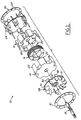
- FIG 1 an exploded view of the relevant portions of a rotor 10 for an electrical machine.
- rotor 10 will recognize rotor 10 as being generally of the Lundell or "claw pole" type, used widely in motor vehicle alternators.
- Rotor 10 includes a first pole piece 12, a second pole piece 14 and a field coil assembly 16.
- First pole piece 12 and second pole piece 14 are mounted on a shaft 18 and enclose field coil assembly 16.
- pole fingers 20 of first pole piece 12 are intermeshed with pole fingers 22 of second pole piece 14.
- Rotor 10 further includes a first fan 24.
- Fan 24 is located at one axial end of the portion of rotor 10 containing pole pieces 12 and 14. Fan 24 is adjacent first pole piece 12.
- a support plate 26 bridges the tips of the blades of fan 24 to provide added support for the fan blades.
- Rotor 10 also includes a second fan 28.
- Fan 28 is located at the opposite axial end of the portion of rotor 10 containing pole pieces 12 and 14. Fan 28 is adjacent second pole piece 14.
- a support plate 30 bridges the tips of the blades of fan 28 to provide added support for the fan blades.
- Pole piece 12 is made of a ferromagnetic material and comprises a body 32 and six pole fingers 20 extending axially from body 32. Pole piece 12 also includes a hub 34 adapted to fit within field coil assembly 16.
- Second pole piece 14 is preferably identical to first pole piece 12, to provide economies of scale in manufacturing pole pieces 12 and 14.
- Fan 24 is preferably molded of plastic. Fan 24 has six preferably enclosed pockets 36. Each pocket 36 contains an insert-molded permanent magnet 38. Permanent magnets 38 can be of any known permanent magnet material, including but not limited to ferrite and rare earth magnetic material. An advantage of designing pockets 36 to fully enclose magnets 38 is that magnets 38 are then protected from corrosion during service in rotor 10. Each pocket 36 is located so that when fan 24 is assembled into rotor 10, a pocket 36 is pressed under a pole finger 22 of second pole piece 14 and above body 32 of first pole piece 12. This is preferably a very snug or interference fit.
- each pocket 36 can be molded with an opening allowing for insertion of a magnet 38.
- the pocket 36 can then be sealed with a potting material.
- Fan 24 further includes a plurality of fan blades 40.
- Each fan blade 40 has a projection 42.
- Each projection 42 is designed to fit through a complementary opening 44 (see Fig. 1) in support plate 26.
- Support plate 26 is preferably stamped from metal but can be any material which provides added structural support to fan blades 40, particularly during high-speed rotation of rotor 10. After assembly of support plate 26 onto blades 40, projections 42 are preferably heat-staked to hold support plate 26 onto blades 40.
- Fan 24 also includes a plurality of posts 46, each post terminating in a tip 48.
- posts 46 span past pole pieces 12 and 14 to fan 28.
- Fan 28 is identical in all relevant respects to fan 24, except that fan 28 has complementary holes 51 (see Fig. 1) sized to accept tips 48 of posts 46.
- tips 48 are heat-staked to fasten fan 24 to fan 28.
- Fans 24 and 28 are thus affixed for rotation with pole pieces 12 and 14.
- Fans 24 and 28 can be further affixed within rotor 10 to the respective pole pieces 12 and 14 by additional means, such as adhesive. Because fan 28 is coupled to integrally-formed posts 46 of fan 24, fans 24 and 28 can be said to be directly coupled together.
- fan 28 is identical in all relevant respects to fan 24 but for the provision of complementary holes for insertion of tips 48 of posts 46 of fan 24. Accordingly, like fan 24, fan 28 has six pockets 50 (see Fig. 1) which each enclose a permanent magnet. In the assembly of rotor 10, each pocket of fan 28 is pressed under a pole finger 20 of first pole piece 12 and above the body of second pole piece 14. Again, this is preferably a very snug or interference fit.
- Figure 4 is an end view of rotor 10 with fan 28 and support plate 30 removed for ease in further illustrating rotor 10.
- one pocket 36 is shown in cross-section to reveal the permanent magnet 38 disposed within.
- Figure 4 also illustrates the locations where posts 46 of fan 24 are routed through rotor 10 for subsequent attachment to fan 28.
- Figure 4 illustrates the location of each pocket 36 of fan 24 between a pole finger 20 of pole piece 12 and the body of pole piece 14.
- FIG. 5 a cross-sectional side view of rotor 10, with shaft 18 removed for aid in illustration. Visible in Figure 5 are two pockets 50 of fan 28, with their associated permanent magnets 52 enclosed within. Also visible in Figure 5 is a tip 48 of a post 46 of fan 24. As was discussed above, the tips 48 are heat-staked to fasten fans 24 and 28 together and to help affix them for rotation with pole pieces 12 and 14. Figure 5 also illustrates some of the projections 42 of the blades 40 of fan 24 and some of the projections 54 of the blades 56 of fan 28. Projections 42 and 54 are heat staked to the respective support plates 26 and 30 of fans 24 and 28. Figure 5 shows tip 48 and projections 42 and 54 prior to heat-staking.
- pole pieces 12 and 14 can also be employed.
- the pole fingers of those pole pieces can be tapered to a reduced lateral dimension at their tips (like a more conventional Lundell rotor). Also, the lateral edges of the pole fingers can be beveled.
- Such an alternative design for pole pieces 12 and 14 may have the benefit of reducing audible noise when the rotor rotates.
- Rotors such as the embodiments of rotor 10 disclosed herein provide many advantages when employed in an electrical machine.
- provision of the permanent magnets provides substantially increased power density and efficiency when compared to standard Lundell rotors.
- the location of the permanent magnets beneath the ends of the pole fingers of pole pieces 12 and 14 provides the added benefit of allowing the pole fingers of each pole piece 12 and 14 to extend over the body of the other pole piece, reducing the overall length of rotor 10. In a typical Lundell rotor, this configuration would cause considerable electromagnetic flux leakage from the pole fingers of one pole piece to the body of the other pole piece.
- the permanent magnets as located in this disclosure greatly reduce or prevent such leakage.
- alternators containing rotors of the design described herein have been shown to provide their increased electrical output with control accomplished by a conventional unidirectional voltage regulator.
- Bidirectional voltage regulators add cost and complexity over conventional unidirectional voltage regulators.
- a further advantage of the rotor design disclosed herein is in the corrosion resistance provided to the permanent magnets by encapsulating them within the pockets of fans 24 and 28. Additionally, support plates 26 and 30 for fans 24 and 28 allow the blades of fans 24 and 28 to be made relatively tall and have considerable structural integrity, even at high rotational speeds of rotor 10. The tall fan blades increase cooling airflow for rotor 10 and for the stator (not shown) of the machine containing rotor 10. Providing support plates 26 and 30 as separate parts from fans 24 and 28 allows significant flexibility in molding fans 24 and 28. Including support plates 26 and 30 as integrally formed with fans 24 and 28 would considerably constrain the ability to mold fans 24 and 28.
- Additional advantages of this embodiment of the present invention are secure retention of the permanent magnets within the pockets of fans 24 and 28 and the increased assembly efficiency of the rotor when the permanent magnets are located within the pockets of fans 24 and 28.
Landscapes
- Engineering & Computer Science (AREA)
- Power Engineering (AREA)
- Permanent Field Magnets Of Synchronous Machinery (AREA)
- Motor Or Generator Cooling System (AREA)
- Synchronous Machinery (AREA)
- Permanent Magnet Type Synchronous Machine (AREA)
Description
Claims (9)
- A rotor for an electrical machine, said rotor comprising:characterised in that the fan (24) is located adjacent one of said pole pieces (12, 14) and each pocket (36) thereof extends under the distal end of a pole finger of the opposite pole piece (12,14).first and second pole pieces (12,14) arranged opposite each other and defining an axis of rotation of said rotor;said first pole piece (12) comprising a body (32) and a plurality of pole fingers (20) extending axially from said body (32) of said first pole piece (12);said second pole piece (14) comprising a body and a plurality of pole fingers (22) extending axially from said body of said second pole piece (14) intermeshed with said pole fingers (20) of said first pole piece (12);a fan (24) affixed for rotation with said first and second pole pieces (12,14), said fan (24) having a plurality of pockets (36), each pocket (36) containing a permanent magnet (38),
- A rotor as claimed in claim 1, wherein the body (32) of the first pole piece (12) has a plurality of outwardly-opening recesses, each such recess being located between a consecutive pair of the pole fingers (20) of the first pole piece (12) and each of the pockets (36) extending into one of the recesses.
- A rotor as claimed in claim 1 or 2, wherein the pockets (36) are integral with the fan (24) and substantially enclose the permanent magnets (38).
- A rotor as claimed in claim 1, 2 or 3, wherein the fan (24) comprises fan blades (40) extending axially outward from the rotor, each fan blade (40) having a tip; and the fan (24) further comprises a support member (26) fastened to and bridging the tips of the fan blades (40).
- A rotor as claimed in claim 4, wherein the tan blade tips each includes a projection (42) projecting through the support member (26), the support member (26) being ir the form of a substantially annular plate (26).
- A rotor as claimed in any one of the preceding claims. wherein the fan (24) constitutes one of two such fans (24,28) a first (24) of which is located adjacent the first pole piece (12) and a second (28) of which is located adjacent the second pole piece (14), the two fans (24,26) being directly coupled together.
- A rotor as claimed in claim 6, wherein the first fan (24) comprises integral axially-extending projections (46) coupled to the second fan (28).
- A rotor as claimed in claim 1, wherein the ends of the pole fingers of the second pole piece (14) extend over the body (32) of the first pole piece (12).
- A rotor as claimed in claim 8, wherein each pocket (36) of the fan (24) extends between the end of a pole finger (22) of the second pole piece (14) and the body of the first pole piece (14).
Applications Claiming Priority (3)
| Application Number | Priority Date | Filing Date | Title |
|---|---|---|---|
| US08/906,548 US5793143A (en) | 1997-08-05 | 1997-08-05 | Rotor for an electrical machine |
| US906548 | 1997-08-05 | ||
| PCT/GB1998/002294 WO1999008365A1 (en) | 1997-08-05 | 1998-07-31 | Rotor for an electrical machine |
Publications (2)
| Publication Number | Publication Date |
|---|---|
| EP1002357A1 EP1002357A1 (en) | 2000-05-24 |
| EP1002357B1 true EP1002357B1 (en) | 2001-10-24 |
Family
ID=25422639
Family Applications (1)
| Application Number | Title | Priority Date | Filing Date |
|---|---|---|---|
| EP98936561A Expired - Lifetime EP1002357B1 (en) | 1997-08-05 | 1998-07-31 | Rotor for an electrical machine |
Country Status (6)
| Country | Link |
|---|---|
| US (1) | US5793143A (en) |
| EP (1) | EP1002357B1 (en) |
| JP (1) | JP2002527015A (en) |
| AU (1) | AU8552398A (en) |
| DE (1) | DE69802196T2 (en) |
| WO (1) | WO1999008365A1 (en) |
Families Citing this family (32)
| Publication number | Priority date | Publication date | Assignee | Title |
|---|---|---|---|---|
| US5962942A (en) * | 1996-05-31 | 1999-10-05 | The Turbo Genset Company Limited | Rotary electrical machines |
| FR2786624B1 (en) * | 1998-11-30 | 2001-02-16 | Valeo Equip Electr Moteur | VEHICLE ALTERNATOR ROTOR WITH PERMANENT MAGNETS |
| US6172441B1 (en) | 1999-06-28 | 2001-01-09 | Visteon Global Technologies, Inc. | Rotor assembly |
| JP3449330B2 (en) * | 2000-01-31 | 2003-09-22 | 株式会社日立製作所 | AC generator for vehicles |
| US6426581B1 (en) | 2000-05-22 | 2002-07-30 | Ford Motor Company | Magnet retainer ring for vehicle alternators |
| JP3974315B2 (en) * | 2000-07-25 | 2007-09-12 | 三菱電機株式会社 | AC generator |
| JP2002095079A (en) * | 2000-09-12 | 2002-03-29 | Citizen Electronics Co Ltd | Multifunctional sound system |
| US20040250273A1 (en) * | 2001-04-02 | 2004-12-09 | Bellsouth Intellectual Property Corporation | Digital video broadcast device decoder |
| US6724115B2 (en) * | 2001-10-24 | 2004-04-20 | Denso Corporation | High electrical and mechanical response structure of motor-generator |
| FR2833774B1 (en) * | 2001-12-18 | 2005-02-04 | Valeo Equip Electr Moteur | ROTOR WITH DOUBLE INDUCTION CIRCUIT FOR A ROTATING ELECTRICAL MACHINE, SUCH AS AN ALTERNATOR, IN PARTICULAR FOR A MOTOR VEHICLE |
| JP3964302B2 (en) * | 2002-10-15 | 2007-08-22 | 三菱電機株式会社 | Rotating electrical machine rotor |
| US6744165B2 (en) * | 2002-10-29 | 2004-06-01 | Visteon Global Technologies, Inc. | High power permanent magnet hybrid alternator rotor |
| US6781262B2 (en) * | 2003-01-29 | 2004-08-24 | Delphi Technologies, Inc. | Generator and air deflector |
| US6812602B2 (en) * | 2003-03-13 | 2004-11-02 | Visteon Global Technologies, Inc. | Apparatus and method for retaining a cooling fan |
| JP2005204480A (en) * | 2004-01-19 | 2005-07-28 | Mitsubishi Electric Corp | Rotating electric machine rotor and rotating electric machine |
| FR2866993B1 (en) * | 2004-02-27 | 2006-04-28 | Valeo Equip Electr Moteur | ROTORIC ASSEMBLY OF WHICH AT LEAST ONE INTERFERRED SPACE IS BLOCKED BY THE FAN |
| EP2073361B1 (en) | 2006-10-10 | 2017-08-09 | Mitsubishi Electric Corporation | Dynamoelectric machine |
| JP4344395B2 (en) | 2007-07-03 | 2009-10-14 | 三菱電機株式会社 | Rotating electric machine |
| WO2009072316A1 (en) * | 2007-12-07 | 2009-06-11 | Mitsubishi Electric Corporation | Rotating electric machine |
| JP4974865B2 (en) * | 2007-12-07 | 2012-07-11 | 三菱電機株式会社 | Rotating electric machine |
| US8304951B2 (en) | 2008-02-13 | 2012-11-06 | Mitsubishi Electric Corporation | Dynamoelectric machine |
| CN101978583B (en) | 2008-03-21 | 2013-02-27 | 三菱电机株式会社 | Rotating electrical machine for vehicle |
| JP4974948B2 (en) * | 2008-04-01 | 2012-07-11 | 三菱電機株式会社 | Rotating electric machine |
| WO2009122596A1 (en) * | 2008-04-01 | 2009-10-08 | 三菱電機株式会社 | Rotary electric machine |
| WO2009122586A1 (en) * | 2008-04-04 | 2009-10-08 | 三菱電機株式会社 | Rotating electrical machine |
| JP5111410B2 (en) * | 2009-02-12 | 2013-01-09 | 三菱電機株式会社 | Rotating electric machine |
| JPWO2012001817A1 (en) * | 2010-07-02 | 2013-08-22 | 株式会社日立製作所 | AC generator for vehicles |
| WO2012067223A1 (en) | 2010-11-19 | 2012-05-24 | アスモ 株式会社 | Rotor and motor |
| DE102011087273B4 (en) * | 2011-11-29 | 2015-10-08 | Robert Bosch Gmbh | Electric machine |
| JP6014481B2 (en) * | 2012-12-07 | 2016-10-25 | 株式会社日本自動車部品総合研究所 | Rotor for rotating electrical machine for vehicles |
| FR3028359B1 (en) * | 2014-11-12 | 2018-05-18 | Valeo Equipements Electriques Moteur | ROTOR OF ROTATING ELECTRIC MACHINE |
| FR3083389B1 (en) * | 2018-06-27 | 2022-01-21 | Valeo Equip Electr Moteur | POLAR ROTOR WHEEL FOR ROTATING ELECTRIC MACHINE |
Citations (1)
| Publication number | Priority date | Publication date | Assignee | Title |
|---|---|---|---|---|
| JPH04165950A (en) * | 1990-10-26 | 1992-06-11 | Nippondenso Co Ltd | Rotor of electric rotating machine for vehicle |
Family Cites Families (14)
| Publication number | Priority date | Publication date | Assignee | Title |
|---|---|---|---|---|
| US3346749A (en) * | 1965-02-02 | 1967-10-10 | Trw Inc | Self-excited brushless alternator |
| DE1488353A1 (en) * | 1965-07-15 | 1969-06-26 | Siemens Ag | Permanent magnet excited electrical machine |
| US3555327A (en) * | 1969-03-25 | 1971-01-12 | Ambac Ind | Permanent magnet alternator with regulating means |
| DE3410760A1 (en) * | 1984-03-23 | 1985-09-26 | Robert Bosch Gmbh, 7000 Stuttgart | ELECTRIC GENERATOR, ESPECIALLY FOR VEHICLES |
| DE3704156A1 (en) * | 1987-02-11 | 1988-08-25 | Bosch Gmbh Robert | AC GENERATOR WITH CLAW POLO ROTOR |
| US5130595A (en) * | 1987-11-23 | 1992-07-14 | Chrysler Corporation | Multiple magnetic paths machine |
| US4980595A (en) * | 1987-11-23 | 1990-12-25 | Chrysler Corporation | Multiple magnetic paths machine |
| SE459833B (en) * | 1987-12-09 | 1989-08-07 | Astra Tech Ab | ROTATING ELECTRIC MACHINE |
| US4882515A (en) * | 1988-06-03 | 1989-11-21 | General Motors Corporation | Alternating current generator |
| US4959577A (en) * | 1989-10-23 | 1990-09-25 | General Motors Corporation | Alternating current generator |
| JP2946604B2 (en) * | 1990-02-26 | 1999-09-06 | 株式会社デンソー | AC generator |
| US5177391A (en) * | 1990-03-14 | 1993-01-05 | Nippondenso Co., Ltd. | Power generating apparatus |
| DE69305118T2 (en) * | 1992-07-20 | 1997-02-06 | Gen Motors Corp | Process for the production of magnetic rotor parts |
| FR2737617B1 (en) * | 1995-08-02 | 1997-10-24 | Valeo Equip Electr Moteur | ALTERNATOR WITH IMPROVED VENTILATION MEANS, PARTICULARLY FOR MOTOR VEHICLE |
-
1997
- 1997-08-05 US US08/906,548 patent/US5793143A/en not_active Expired - Lifetime
-
1998
- 1998-07-31 EP EP98936561A patent/EP1002357B1/en not_active Expired - Lifetime
- 1998-07-31 AU AU85523/98A patent/AU8552398A/en not_active Abandoned
- 1998-07-31 WO PCT/GB1998/002294 patent/WO1999008365A1/en not_active Ceased
- 1998-07-31 JP JP2000506712A patent/JP2002527015A/en active Pending
- 1998-07-31 DE DE69802196T patent/DE69802196T2/en not_active Expired - Fee Related
Patent Citations (1)
| Publication number | Priority date | Publication date | Assignee | Title |
|---|---|---|---|---|
| JPH04165950A (en) * | 1990-10-26 | 1992-06-11 | Nippondenso Co Ltd | Rotor of electric rotating machine for vehicle |
Also Published As
| Publication number | Publication date |
|---|---|
| EP1002357A1 (en) | 2000-05-24 |
| DE69802196D1 (en) | 2001-11-29 |
| AU8552398A (en) | 1999-03-01 |
| DE69802196T2 (en) | 2002-07-04 |
| WO1999008365A1 (en) | 1999-02-18 |
| US5793143A (en) | 1998-08-11 |
| JP2002527015A (en) | 2002-08-20 |
Similar Documents
| Publication | Publication Date | Title |
|---|---|---|
| US5793143A (en) | Rotor for an electrical machine | |
| EP0732795B1 (en) | Rotating electrical machine | |
| US5925964A (en) | Rotor for a rotating electric machine | |
| US5672926A (en) | Hybrid-energized electric machine | |
| JP3318531B2 (en) | Rotating electric machine and its bearing structure | |
| US6784586B2 (en) | Hybrid alternator with an axial end retainer for permanent magnets | |
| JP4860867B2 (en) | Fluid pump having motor casing and method for manufacturing motor casing | |
| US5962938A (en) | Motor with external rotor | |
| JP4477072B2 (en) | Rotating electric machine | |
| US20160197535A1 (en) | Electric machine | |
| JP2003527061A (en) | Multi-phase rotating electrical equipment | |
| EP0881755A3 (en) | Rotor positioning magnets | |
| US8398378B2 (en) | Tangential drive module assembly and method of assembly for airflow induction | |
| EP0244134B2 (en) | Cooling in electric motors | |
| WO2005043723B1 (en) | Brushless permanent magnet motor with high power density, low cogging and low vibration | |
| JP3370514B2 (en) | Brushless electric motor | |
| US20070024131A1 (en) | Ventilator for an alternator-starter | |
| EP1443627B1 (en) | Generator with air deflector | |
| WO1998029938A3 (en) | A high performance electric motor | |
| JP2865094B2 (en) | AC generator | |
| CN101904078B (en) | Target bracket assembly on the fan of the rotating motor | |
| RU13522U1 (en) | MOTOR PART OF THE MOTOR | |
| JP4235431B2 (en) | Single-phase magnet generator | |
| KR19990013754U (en) | Rotor for motor | |
| KR100193430B1 (en) | Permanent Magnet Synchronous Motor |
Legal Events
| Date | Code | Title | Description |
|---|---|---|---|
| PUAI | Public reference made under article 153(3) epc to a published international application that has entered the european phase |
Free format text: ORIGINAL CODE: 0009012 |
|
| 17P | Request for examination filed |
Effective date: 20000120 |
|
| AK | Designated contracting states |
Kind code of ref document: A1 Designated state(s): DE FR GB |
|
| GRAG | Despatch of communication of intention to grant |
Free format text: ORIGINAL CODE: EPIDOS AGRA |
|
| 17Q | First examination report despatched |
Effective date: 20010504 |
|
| GRAG | Despatch of communication of intention to grant |
Free format text: ORIGINAL CODE: EPIDOS AGRA |
|
| GRAH | Despatch of communication of intention to grant a patent |
Free format text: ORIGINAL CODE: EPIDOS IGRA |
|
| GRAH | Despatch of communication of intention to grant a patent |
Free format text: ORIGINAL CODE: EPIDOS IGRA |
|
| GRAA | (expected) grant |
Free format text: ORIGINAL CODE: 0009210 |
|
| AK | Designated contracting states |
Kind code of ref document: B1 Designated state(s): DE FR GB |
|
| REF | Corresponds to: |
Ref document number: 69802196 Country of ref document: DE Date of ref document: 20011129 |
|
| REG | Reference to a national code |
Ref country code: GB Ref legal event code: IF02 |
|
| ET | Fr: translation filed | ||
| PLBE | No opposition filed within time limit |
Free format text: ORIGINAL CODE: 0009261 |
|
| STAA | Information on the status of an ep patent application or granted ep patent |
Free format text: STATUS: NO OPPOSITION FILED WITHIN TIME LIMIT |
|
| 26N | No opposition filed | ||
| PGFP | Annual fee paid to national office [announced via postgrant information from national office to epo] |
Ref country code: GB Payment date: 20030704 Year of fee payment: 6 |
|
| PGFP | Annual fee paid to national office [announced via postgrant information from national office to epo] |
Ref country code: DE Payment date: 20030710 Year of fee payment: 6 |
|
| PGFP | Annual fee paid to national office [announced via postgrant information from national office to epo] |
Ref country code: FR Payment date: 20030711 Year of fee payment: 6 |
|
| PG25 | Lapsed in a contracting state [announced via postgrant information from national office to epo] |
Ref country code: GB Free format text: LAPSE BECAUSE OF NON-PAYMENT OF DUE FEES Effective date: 20040731 |
|
| PG25 | Lapsed in a contracting state [announced via postgrant information from national office to epo] |
Ref country code: DE Free format text: LAPSE BECAUSE OF NON-PAYMENT OF DUE FEES Effective date: 20050201 |
|
| GBPC | Gb: european patent ceased through non-payment of renewal fee |
Effective date: 20040731 |
|
| PG25 | Lapsed in a contracting state [announced via postgrant information from national office to epo] |
Ref country code: FR Free format text: LAPSE BECAUSE OF NON-PAYMENT OF DUE FEES Effective date: 20050331 |
|
| REG | Reference to a national code |
Ref country code: FR Ref legal event code: ST |