EP1001558A2 - Communication terminal apparatus and radio communication method with transmission diversity - Google Patents
Communication terminal apparatus and radio communication method with transmission diversity Download PDFInfo
- Publication number
- EP1001558A2 EP1001558A2 EP99122264A EP99122264A EP1001558A2 EP 1001558 A2 EP1001558 A2 EP 1001558A2 EP 99122264 A EP99122264 A EP 99122264A EP 99122264 A EP99122264 A EP 99122264A EP 1001558 A2 EP1001558 A2 EP 1001558A2
- Authority
- EP
- European Patent Office
- Prior art keywords
- channel
- antenna
- estimated value
- signal
- antennas
- Prior art date
- Legal status (The legal status is an assumption and is not a legal conclusion. Google has not performed a legal analysis and makes no representation as to the accuracy of the status listed.)
- Withdrawn
Links
- 238000004891 communication Methods 0.000 title claims abstract description 112
- 238000000034 method Methods 0.000 title claims description 14
- 230000005540 biological transmission Effects 0.000 title description 68
- 230000001427 coherent effect Effects 0.000 description 16
- 238000001514 detection method Methods 0.000 description 16
- 238000010586 diagram Methods 0.000 description 11
- 238000012545 processing Methods 0.000 description 6
- 238000001228 spectrum Methods 0.000 description 3
- 238000012935 Averaging Methods 0.000 description 2
- 230000001413 cellular effect Effects 0.000 description 2
- 238000005516 engineering process Methods 0.000 description 2
- 239000008186 active pharmaceutical agent Substances 0.000 description 1
- 238000007796 conventional method Methods 0.000 description 1
- 230000002596 correlated effect Effects 0.000 description 1
- 230000000875 corresponding effect Effects 0.000 description 1
- 230000003111 delayed effect Effects 0.000 description 1
- 230000002542 deteriorative effect Effects 0.000 description 1
- 239000000284 extract Substances 0.000 description 1
- 238000005562 fading Methods 0.000 description 1
- 238000012986 modification Methods 0.000 description 1
- 230000004048 modification Effects 0.000 description 1
- 230000002093 peripheral effect Effects 0.000 description 1
- 230000008054 signal transmission Effects 0.000 description 1
Images


Classifications
-
- H—ELECTRICITY
- H04—ELECTRIC COMMUNICATION TECHNIQUE
- H04B—TRANSMISSION
- H04B1/00—Details of transmission systems, not covered by a single one of groups H04B3/00 - H04B13/00; Details of transmission systems not characterised by the medium used for transmission
- H04B1/76—Pilot transmitters or receivers for control of transmission or for equalising
-
- H—ELECTRICITY
- H04—ELECTRIC COMMUNICATION TECHNIQUE
- H04B—TRANSMISSION
- H04B7/00—Radio transmission systems, i.e. using radiation field
- H04B7/02—Diversity systems; Multi-antenna system, i.e. transmission or reception using multiple antennas
- H04B7/04—Diversity systems; Multi-antenna system, i.e. transmission or reception using multiple antennas using two or more spaced independent antennas
- H04B7/06—Diversity systems; Multi-antenna system, i.e. transmission or reception using multiple antennas using two or more spaced independent antennas at the transmitting station
- H04B7/0602—Diversity systems; Multi-antenna system, i.e. transmission or reception using multiple antennas using two or more spaced independent antennas at the transmitting station using antenna switching
- H04B7/0604—Diversity systems; Multi-antenna system, i.e. transmission or reception using multiple antennas using two or more spaced independent antennas at the transmitting station using antenna switching with predefined switching scheme
Definitions
- the present invention relates to a communication terminal apparatus and radio communication method used in a radio communication system.
- a multiple access system refers to a channel access system in which a plurality of stations perform communications using a same band simultaneously.
- CDMA in this multiple access system refers to Code Division Multiple Access, a technology implementing multiple accesses through spread spectrum communications with the spectrum of an information signal spread over a sufficiently wide band with respect to the original information bandwidth. It is also called “spread spectrum multiple access (SSMA)."
- TPC Transmit Power Control
- a communication channel assigned to each user according to conditions of the transmission path between communicating parties.
- a plurality of communications share a same frequency, which gives rise to a problem (near-far problem) that the power of an interference signal (a communication wave of another station) coincides with the power of a desired signal at the receiving end. Solving this problem is a premise in realizing the CDMA system.
- TPC is also carried out on the downlink (channel from a base station to a mobile station) in accordance with the SIR (signal to interference ratio) due to fading variations or interference from peripheral cells.
- a channel estimation technology to carry out coherent detection is essential to CDMA.
- the channel estimation system as described in "DS/CDMA Weighted Multi-Symbol Averaging (WMSA) Pilot Channel Characteristics" by Abeta, Ando, Sawabashi, Adachi, et al. (TECHNICAL REPORT OF IEICE RC97-163, 1997-11), two systems are available; a time-division type pilot channel system that inserts a pilot symbol periodically and a parallel pilot channel system that carries out transmission by continuously suppressing power.
- WMSA Weighted Multi-Symbol Averaging
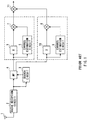
- FIG.1 is a block diagram showing a configuration of a receiver comprising channel estimation apparatuses based on a time-multiplexing type pilot channel system.
- the transmitting side carries out transmission by inserting Np pilot data for every Ns transmit data symbols.
- a signal received by antenna 1 is down-converted and demodulated by radio reception circuit 2, then despread by matched filter 4 at a timing detected by search circuit 3.
- Pilot symbols are extracted from the despreading signal, their data corresponding to several slots are accumulated and channel estimation is carried out by channel estimation circuits 5 and 6 based on that information.
- the despreading signal is subjected to coherent detection by coherent detection sections 7 and 8 using estimated values obtained by channel estimation circuits 5 and 6, and with a time delay compensated by delay processing sections 9 and 10, the signals of these paths are combined at a maximum ratio (RAKE combining) in combination section 11.
- the channel estimation system is based on the principle as follows: Suppose an estimated value of complex impulse response of the mth symbol of the nth slot of the first branch is given by expression (1) below. The complex impulse response after synchronization addition is expressed in expression (2), and using pilot symbols of a plurality of slots before and after the slot the channel estimated value shown in expression (3) is obtained. h l ( n,m )
- ⁇ i ( ⁇ 1) is a weighting factor.
- the conventional system has a problem that if a transmit signal of another channel is sent from a plurality of antennas through diversity transmission, only pilot signals of the self channel are used for channel estimation although the other channel also has pilot signals.
- the transmit timing of a pilot signal differs between the self channel and the other channel, although the pilot signal of the other channel contains the channel status information on a section that cannot be obtained from the pilot signal of the self channel, this information is not used for channel estimation.
- a CDMA cellular radio communication apparatus is generally equipped with a plurality of demodulation systems (correlators and channel estimation circuits) for soft handover and RAKE combining. Enabling these demodulation systems to be switched according to the situation will make it possible to estimate the channel condition of the other channel without further adding any demodulation systems above.
- demodulation systems correlators and channel estimation circuits
- the inventor, et al. came up with the present invention by taking notice of the fact that when transmit signals from other channels including pilot signals are transmitted from a plurality of antennas through diversity transmission, only pilot signals of the self channel are used for channel estimation, and discovering that it would be possible to improve the accuracy of channel estimation by carrying out channel estimation using not only pilot signal of the self channel but also pilot signals of other channels.
- a communication terminal apparatus comprising a first channel estimation circuit that extracts known reference signals in control channels from signals transmitted from a plurality of antennas, estimates respective channel conditions and obtains a first estimated value; a second channel estimation circuit that estimates the channel condition of a communication channel signal from signals transmitted from a plurality of antennas and obtains a second estimated value; an antenna estimation circuit that estimates the antenna that transmitted the aforementioned communication signal from the aforementioned plurality of antennas using the first and second estimated values above; and a combination circuit that obtains a combined estimated value by combining the first estimated value and second estimated value about the estimated antenna.
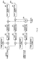
- FIG.2 is a block diagram showing a configuration of a transmission terminal apparatus according to an embodiment of the present invention.
- FIG.3 is a block diagram showing a configuration of a transmission antenna estimation circuit of the communication terminal apparatus shown in FIG.2.
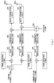
- FIG.4 is a block diagram showing a configuration of a base station apparatus carrying out a radio communication with the communication terminal apparatus shown in FIG.2. The present embodiment is explained below using FIG.2 to FIG.6.
- the present embodiment describes a case using OTD (Orthogonal Transmit Diversity) that transmits a signal converted from serial to parallel from each antenna at a transmission speed reduced to 1/n with a ⁇ n spreading rate.
- OTD Orthogonal Transmit Diversity
- a control channel signal is transmitted with transmission diversity.
- a control channel signal is transmitted with a pattern shown in FIG.5A. That is, known reference signals (pilot signals) 401 are sent from all antennas A and B (here 2 antennas) and other control signals 402 are sent in a predetermined cycle or pattern.
- a communication channel signal is sent, for example, in a cycle or pattern as shown in FIG.6. That is, known reference signals (pilot signals) 501 and data 502 are sent alternatively from either antenna A or antenna B.
- the cycle of switching these antennas can be set as appropriate, for example, on a slot-by-slot basis or on a frame-by-frame basis.
- a base station apparatus with a configuration as shown in FIG.4 is used when performing transmission with transmission diversity using the transmission patterns above.
- a transmission signal in a control channel is converted from serial to parallel by serial/parallel converter 301 (2 paths here). This reduces the transmission speed from each antenna to 1/2.
- These signals are each multiplexed with a known reference signal, sent to data modulation circuit 302, modulated by data modulation circuit 302 and spread using a predetermined spreading code by spreading modulation circuit 303.
- the spreading rate is ⁇ 2.
- the spreading signals are up-converted by radio transmission circuit 304 and transmitted from antennas 305a and 305b.
- a communication channel transmission signal is multiplexed with a known reference signal, sent to data modulation circuit 306, modulated by modulation circuit 306 and spread using a predetermined spreading code by spreading modulation circuit 307.
- the spreading signal is multiplexed with the control signal of either antenna by switch 308 which is switched by a switching signal, up-converted by radio transmission circuit 304 and transmitted from antenna 305a or 305b.
- the signal transmitted in this way is received by the communication terminal apparatus shown in FIG.2.
- the signal received from antenna 101 is down-converted and demodulated by radio reception circuit 102 and despread by matched filters 103a and 103b using the spreading code used for spreading on the transmitting side.
- Matched filter 103a despreads the control channel signal transmitted from antenna 305a of the base station apparatus
- matched filter 103b despreads the control channel signal transmitted from antenna 305b of the base station apparatus
- matched filter 103c despreads the communication channel signal transmitted from antenna 305a or 305b of the base station apparatus.
- Transmission antenna estimation circuit 108 selects the antenna used for transmission based on the estimation results of channel estimation circuits 104 to 106 and calculates weighting factors for combinations.
- Transmission antenna estimation circuit 108 comprises calculation circuit 201 that performs a predetermined operation using the estimation results of first to third channel estimation circuits 104 to 106, comparison circuit 202 that compares the operation results of calculation circuit 201, determination circuit 203 that determines antenna estimation based on the comparison result of comparison circuit 202 and weighting calculation circuit 204 that finds a weighting factor using the estimation results from first to third channel estimation circuits 104 to 106.
- the antenna estimation information and weighting factor obtained by transmission antenna estimation circuit 108 are sent to combination circuit 109.
- Combination circuit 109 combines the channel estimated values of the control channel signal and communication channel signal according to the antenna estimation information and weighting factor.
- the combined signal is sent to coherent detection circuit 110 and subjected to coherent detection processing with a signal delayed by delay circuit 107 there.
- the reception signals despread by matched filters 103a to 103c are sent to first to third channel estimation circuits 104 to 106, respectively and subjected to channel estimation there. That is, first channel estimation circuit 104 performs channel estimation about the control channel signal sent from antenna 305a of the base station and channel estimation circuit 105 performs channel estimation about the control channel signal sent from antenna 305b of the base station. This channel estimation is performed using known reference signals of several slots.
- third channel estimation circuit 106 performs channel estimation about the communication channel signal sent from either antenna 305a or 305b of the base station. This channel estimation is also performed using known reference signals of several slots. However, if antenna switching for the communication channel signal is performed for each slot, channel estimation is performed using a known reference signal in one slot.
- the channel estimated value of the first path of the nth pilot block can be obtained according to expression (2) above.
- Channel estimated values are calculated from the phase, amplitude and power, etc. These channel estimated values are sent to calculation circuit 201 of transmission antenna estimation circuit 108.
- Calculation circuit 201 calculates the difference between the channel estimated value of the known reference signal sent from antenna 305a of the base station and the channel estimated value of the communication channel signal sent from antenna 305a or 305b of the base station, and the difference between the channel estimated value of the known reference signal sent from antenna 305b of the base station and the channel estimated value of the communication channel signal sent from antenna 305a or 305b of the base station.
- comparison circuit 202 differences of channel estimated values are sent to comparison circuit 202 and compared there. This comparison result is sent to determination circuit 203. If the reliability of the channel estimated value of the communication channel itself is low or the reliability of the channel estimated value of the control channel signal sent from either antenna is low, or if the channel estimated values of both control channel signals have quality equivalent to that of the channel estimated value of the communication channel, it is difficult to determine which antenna sent the communication channel or the reliability of such determination is extremely low, and therefore comparison circuit 203 determines that it is preferable not to combine the channel estimated values and if the comparison result falls below a predetermined threshold comparison circuit 203 does not perform estimation as to which antenna of the base station sent the communication channel.
- comparison circuit 203 determines that it is preferable not to combine the channel estimated values and does not perform antenna estimation. This makes it possible to not only avoid unnecessary processing and reduce burden to the equipment but also prevent channel estimation performance from contrarily deteriorating by combining the channel estimated values.
- This information without antenna estimation is sent to combination circuit 109 as antenna estimation information.
- comparison circuit 203 determines that it is preferable not to combine the channel estimated values and estimate the antenna. In this way, estimation is performed for the antenna whose channel quality is estimated to be high, which allows more accurate channel estimation and coherent detection. Information on which antenna was estimated is sent to combination circuit 109 as antenna estimation information.
- both channel estimated values to be compared are small, it is possible to determine that both antennas have channel estimated values with equally poor quality, and therefore it is possible to determine not to perform antenna estimation in this case, either.
- the channel estimated value above is sent to weighting calculation circuit 204.
- the comparison result of comparison circuit 202 and the determination result of determination circuit 203 are sent to weighting calculation circuit 204.
- Weighting calculation circuit 204 makes a soft decision according to the reliability of the channel-estimated value and finds a weighting factor based on the comparison result and determination result.
- weighting factors are multiplied in this way, it is possible to perform weighting combination of channel estimated values according to the reliability of an channel estimated value and/or the reliability of antenna estimation, making it possible to perform more accurate channel estimation and coherent detection.
- the reliability of a channel estimated value can include the rate of the reception level of a known reference signal of a communication channel signal to the reception level of a known reference signal of a control channel signal or the difference between these two, for example. If the rate of the reception level of a known reference signal of a communication channel signal to the reception level of a known reference signal of a control channel signal or the difference between these two is small, for example, the reliability of a channel estimated value of the control channel is small and so is the reliability of antenna estimation as to which antenna sent the communication channel. Weighting factors are obtained according to that reliability. As shown above, if antenna estimation is performed through the determination above, weighting factors are calculated using the channel estimated values and comparison results. These weighting factors are sent to combination circuit 109.
- Combination circuit 109 combines channel estimation values according to the antenna estimation information and weighting factors from transmission antenna estimation circuit 108. That is, combination circuit 109 combines the channel estimated value of the known reference signal sent from antenna 305a and the channel estimated value of the communication channel signal sent from antenna 305a and antenna 305b by multiplying these estimated values by the weighting factor, or combines the channel estimated value of the known reference signal sent from antenna 305b and the channel estimated value of the communication channel signal sent from antenna 305a and antenna 305b by multiplying these estimated values by the weighting factor.
- the despreading signal is compensated for its time delay in delay processing section 107 and then subjected to coherent detection by coherent detection circuit 110.
- the base station equipped with a plurality of antennas carries out transmission diversity in such a way that control channel signals are sent from all antennas and a communication channel signal is sent from a selected antenna
- the base station combines the channel estimated value of the control channel signal and the channel estimated value of the communication channel signal after estimating a transmission antenna, improving thus the channel estimation performance. This makes it possible to improve the coherent detection performance in the communication terminal apparatus.
- the present embodiment describes a case where the transmitting side (base station) transmits control channel signals in a pattern shown in FIG.5B with transmission diversity.
- control signals 402 are transmitted from specific antenna A.
- a base station apparatus When transmission is performed using the transmission patterns above with transmission diversity, a base station apparatus with a configuration shown in FIG.7 is used.
- a transmission signal in a control channel is switched by switch 601 and transmitted. That is, transmission is performed with the line on the antenna 605a side always connected and by switching the line on the antenna 605b side (here two lines).
- These signals are multiplexed with a known reference signal, sent to data modulation circuit 602, modulated by data modulation circuit 602 and spread by spreading modulation circuit 603 using a predetermined spreading code.
- the spreading signals are un-converted by radio transmission circuit 604 and transmitted from antennas 605a and 605b.
- a communication channel transmission signal is multiplexed with a known reference signal, sent to data modulation circuit 606, modulated by modulation circuit 606 and spread using a predetermined spreading code by spreading modulation circuit 607.
- the spreading signal is multiplexed with the control signal of either antenna by switch 608 which is switched by a switching signal, up-converted by radio transmission circuit 604 and transmitted from antenna 605a or 605b.
- the communication terminal apparatus shown in FIG. 2 receives these signals transmitted in this way.
- the processing of the communication terminal apparatus shown in FIG.2 is the same as that in Embodiment 1.
- the base station equipped with a plurality of antennas carries out transmission diversity in such a way that control channel signals are sent from all antennas and a communication channel signal is sent from a selected antenna
- the base station combines the channel estimated value of the control channel signal and the channel estimated value of the communication channel signal after estimating a transmission antenna, improving thus the channel estimation performance. This makes it possible to improve the coherent detection performance in the communication terminal apparatus.
- the present embodiment describes a case where the transmitting side (base station) transmits control channel signals in a pattern shown in FIG.5C with transmission diversity.
- control signals 402 are alternatively transmitted from antenna A or antenna B in a predetermined cycle or pattern.
- a base station apparatus When transmission is performed using the transmission pattern above with transmission diversity, a base station apparatus with the configuration as shown in FIG.7 is used.
- transmission signals in a control channel are switched by switch 601 and transmitted. That is, transmission is performed by switching the line on the antenna 605a side and the line on the antenna 605b side(here two lines).
- These signals are multiplexed with a known reference signal, sent to data modulation circuit 602, modulated by data modulation circuit 602 and spread by spreading modulation circuit 603 using a predetermined spreading code.
- the spreading signals are un-converted by radio transmission circuit 604 and transmitted from antennas 605a and 605b.
- a communication channel transmission signal is multiplexed with a known reference signal, sent to data modulation circuit 606, modulated by modulation circuit 606 and spread using a predetermined spreading code by spreading modulation circuit 607.
- the spreading signal is multiplexed with a control signal of either antenna by switch 608 which is switched by a switching signal, up-converted by radio transmission circuit 604 and transmitted from antenna 605a or 605b.
- the communication terminal apparatus shown in FIG.2 receives these signals transmitted in this way.
- the processing of the communication terminal apparatus shown in FIG.2 is the same as that in Embodiment 1.
- the base station equipped with a plurality of antennas carries out transmission diversity in such a way that control channel signals are sent from all antennas and a communication channel signal is sent from a selected antenna
- the base station combines the channel estimated value of the control channel signal and the channel estimated value of the communication channel signal after estimating a transmission antenna, improving thus the channel estimation performance. This makes it possible to improve the coherent detection performance in the communication terminal apparatus.
- the transmission patterns in the above embodiments illustrate cases where known reference signals 401 are sent from all antennas A and B simultaneously, but the present invention is also applicable to a case where known reference signals 401 are sent from all antennas A and B at different timings.
- the method of switching transmission antennas by receiving and following a control signal requesting for the switching of antennas from the communication terminal apparatus can prevent combination errors (errors in combining with channel estimated value of control channel of a wrong antenna) caused by erroneous switching of transmission antennas on the base station side due to control signal transmission errors, compared to the case of combining channel estimated values with only antenna estimation control signals.
- This makes it possible to not only perform more accurate antenna estimation but also perform more accurate channel estimation and improve coherent detection performance.
- the communication terminal apparatus of the present invention allows the channel condition of another channel to be estimated without adding a new demodulation system as the one described above by using a plurality of demodulation systems (correlators and channel estimation circuits) for soft handover and RAKE combining generally provided for a CDMA cellular radio transmission apparatus and switching them according to the situation.
- demodulation systems correlators and channel estimation circuits
- the present invention is applicable without particular limitations to any system using transmission diversity as long as it comprises a plurality of antennas, transmits control channel signals from all antennas and transmits communication channels from a selected antenna.
- the communication terminal apparatus of the present invention is suitable for a mobile station in a CDMA radio communication system.
- the channel estimating operation in the communication terminal apparatus may be realize by software.
- the communication terminal apparatus and radio communication method of the present invention carry out transmission diversity in such a way that control channel signals are sent from all antennas and a communication channel signal is sent from a selected antenna and combine the channel estimated value of the control channel signal and the channel estimated value of the communication channel signal after estimating a transmission antenna, improving thus the channel estimation performance.
- This makes it possible to improve the coherent detection performance in the communication terminal apparatus.
Landscapes
- Engineering & Computer Science (AREA)
- Computer Networks & Wireless Communication (AREA)
- Signal Processing (AREA)
- Mobile Radio Communication Systems (AREA)
- Radio Transmission System (AREA)
Abstract
Description

Claims (11)
- A communication terminal apparatus comprising:a first channel estimator(104,105) that obtains a first estimated value by extracting a known reference signal in a control channel from signals transmitted from a plurality of antennas and estimating their respective channel conditions;a second channel estimator(106) that obtains a second estimated value by estimating channel conditions of a communication channel signal from signals transmitted from a plurality of antennas;an antenna estimator(108) that estimates the antenna that sent said communication channel signal from said plurality of antennas using said first and second estimated values; anda combiner(109) that obtains a combined estimated value by combining the first estimated value and second estimated value about the estimated antenna.
- The communication terminal apparatus according to claim 1, wherein the antenna estimator(108) comprises an calculator that finds a plurality of differences between said first estimated value and said second estimated value;a comparator(202) that compares a plurality of estimated value differences; anda determinator(203) that performs threshold determination on the comparison result.
- The communication terminal apparatus according to claim 2, wherein, if said comparison result is not more than the predetermined threshold, the determinator(203) instructs not to perform antenna estimation.
- The communication terminal apparatus according to claim 2, wherein, if said comparison result exceeds the predetermined threshold, the determination circuit instructs to perform antenna estimation.
- The communication terminal apparatus according to claim 1, further comprising:a weighting calculator(204) that calculates weighting factors to be multiplied on the first and second estimated values based on the first and second estimated values and the determination result about antenna estimation.
- A communication terminal apparatus comprising:a first channel estimator(104,105) that obtains a first estimated value by extracting a known reference signal in a control channel from signals transmitted from a plurality of antennas and estimating their respective channel conditions;a second channel estimator(106) that obtains a second estimated value by estimating channel conditions of a communication channel signal from signals transmitted from a plurality of antennas;a transmitter that transmits a control signal to request for switching the antenna for transmitting said communication channel signal;an antenna estimator(108) that estimates the antenna that sent said communication channel signal from said plurality of antennas using said first and second estimated values; anda combiner(109) that obtains a combined estimated value by combining the first estimated value and second estimated value about the estimated antenna.
- A base station apparatus carrying out a radio communication with a communication terminal apparatus, said communication terminal apparatus comprising:a first channel estimator(104,105) that obtains a first estimated value by extracting a known reference signal in a control channel from signals transmitted from a plurality of antennas and estimating their respective channel conditions;a second channel estimator(106) that obtains a second estimated value by estimating channel conditions of a communication channel signal from signals transmitted from a plurality of antennas;an antenna estimator(108) that estimates the antenna that sent said communication channel signal from said plurality of antennas using said first and second estimated values; anda combiner(109) that obtains a combined estimated value by combining the first estimated value and second estimated value about the estimated antenna.
- A radio communication method comprising:the first channel estimating step of obtaining a first estimated value by extracting a known reference signal in a control channel from signals transmitted from a plurality of antennas and estimating their respective channel conditions;the second channel estimating step of obtaining a second estimated value by estimating channel conditions of a communication signal from signals transmitted from a plurality of antennas;the antenna estimating step of estimating the antenna that sent said communication channel signal from said plurality of antennas using said first and second estimated values; andthe combining step of obtaining a combined estimated value by combining the first estimated value and second estimated value about the estimated antenna.
- The radio communication method according to claim 8, wherein the antenna estimating step comprises:the operating step of obtaining a plurality of differences between said first estimated value and said second estimated value;the comparing step of comparing a plurality of differences between estimated values; andthe determining step of performing threshold determination on the comparison result.
- The radio communication method according to claim 8, further comprising the weighting operating step of calculating weighting factors to be multiplied on the first and second estimated values based on the first and second estimated values and the determination result about antenna estimation.
- A radio communication method comprising:the first channel estimating step of obtaining a first estimated value by extracting a known reference signal in a control channel from signals transmitted from a plurality of antennas and estimating their respective channel conditions;the second channel-estimating step of obtaining a second estimated value by estimating channel conditions of a communication signal from signals transmitted from a plurality of antennas;the transmitting step of transmitting a control signal to request for switching the antenna for transmitting said communication channel signal;the antenna estimating step of estimating the antenna that sent said communication channel signal from said plurality of antennas using said first and second estimated values; andthe combining step of obtaining a combined estimated value by combining the first estimated value and second estimated value about the estimated antenna.
Applications Claiming Priority (2)
| Application Number | Priority Date | Filing Date | Title |
|---|---|---|---|
| JP32075898 | 1998-11-11 | ||
| JP32075898A JP3369489B2 (en) | 1998-11-11 | 1998-11-11 | Wireless communication device and wireless communication method |
Publications (2)
| Publication Number | Publication Date |
|---|---|
| EP1001558A2 true EP1001558A2 (en) | 2000-05-17 |
| EP1001558A3 EP1001558A3 (en) | 2003-06-04 |
Family
ID=18124946
Family Applications (1)
| Application Number | Title | Priority Date | Filing Date |
|---|---|---|---|
| EP19990122264 Withdrawn EP1001558A3 (en) | 1998-11-11 | 1999-11-08 | Communication terminal apparatus and radio communication method with transmission diversity |
Country Status (5)
| Country | Link |
|---|---|
| EP (1) | EP1001558A3 (en) |
| JP (1) | JP3369489B2 (en) |
| KR (1) | KR100355327B1 (en) |
| CN (1) | CN1256564A (en) |
| CA (1) | CA2288486A1 (en) |
Cited By (5)
| Publication number | Priority date | Publication date | Assignee | Title |
|---|---|---|---|---|
| EP1191755A3 (en) * | 2000-09-26 | 2005-03-16 | Nokia Corporation | Antenna phase estimation algorithm for WCDMA closed loop transmitter antenna diversity system |
| WO2010147416A3 (en) * | 2009-06-18 | 2011-03-31 | Lg Electronics Inc. | Method and apparatus for feeding back channel state information |
| US8780829B2 (en) | 2008-12-11 | 2014-07-15 | Lg Electronics Inc. | Method for transmitting and receiving a comp reference signal in a multi-cell environment |
| CN113455056A (en) * | 2019-02-18 | 2021-09-28 | 苹果公司 | System and method for uplink panel selection with power saving |
| US11411633B2 (en) | 2018-02-01 | 2022-08-09 | Nippon Telegraph And Telephone Corporation | Transmission device, wireless communication system, and transmission method |
Families Citing this family (12)
| Publication number | Priority date | Publication date | Assignee | Title |
|---|---|---|---|---|
| JP3732364B2 (en) * | 1999-08-27 | 2006-01-05 | 松下電器産業株式会社 | Communication terminal apparatus and channel estimation method |
| CN1146163C (en) * | 2000-10-20 | 2004-04-14 | 华为技术有限公司 | A Method of Improving the Accuracy of Channel Estimation in TD-CDMA System |
| JP3676986B2 (en) | 2001-03-29 | 2005-07-27 | 松下電器産業株式会社 | Radio receiving apparatus and radio receiving method |
| JP4588931B2 (en) * | 2001-07-05 | 2010-12-01 | 株式会社東芝 | Mobile radio terminal |
| US8165186B2 (en) * | 2005-08-12 | 2012-04-24 | Qualcomm Incorporated | Channel estimation for wireless communication |
| KR101481591B1 (en) * | 2008-12-03 | 2015-01-12 | 엘지전자 주식회사 | A method of transmitting and receiving a downlink reference signal in a wireless communication system having multiple antennas |
| WO2010064794A2 (en) * | 2008-12-05 | 2010-06-10 | 엘지전자 주식회사 | Method for transmitting and receiving a comp reference signal in a multi-cell environment |
| KR20100066255A (en) | 2008-12-09 | 2010-06-17 | 엘지전자 주식회사 | Method of transmitting and receiving uplink reference signal in a wireless communication system having multiple antennas |
| KR101689597B1 (en) | 2009-02-09 | 2016-12-26 | 엘지전자 주식회사 | Method for transmitting reference signals in downlink multiple input multiple output |
| US10218481B2 (en) | 2009-04-22 | 2019-02-26 | Lg Electronics Inc. | Apparatus and method for transmitting a reference signal in a wireless communication system |
| KR101715397B1 (en) * | 2009-04-22 | 2017-03-13 | 엘지전자 주식회사 | Apparatus and method for transmitting reference signal in wireless communication system |
| CN106656253B (en) * | 2016-12-08 | 2023-03-14 | 南京信息工程大学 | Ka-band MIMO (multiple input multiple output) transceiver for cloud target detection experiment |
Family Cites Families (1)
| Publication number | Priority date | Publication date | Assignee | Title |
|---|---|---|---|---|
| US5901185A (en) * | 1996-04-15 | 1999-05-04 | Ericsson Inc. | Systems and methods for data-augmented, pilot-symbol-assisted radiotelephone communications |
-
1998
- 1998-11-11 JP JP32075898A patent/JP3369489B2/en not_active Expired - Fee Related
-
1999
- 1999-11-03 CA CA 2288486 patent/CA2288486A1/en not_active Abandoned
- 1999-11-08 EP EP19990122264 patent/EP1001558A3/en not_active Withdrawn
- 1999-11-11 KR KR1019990049889A patent/KR100355327B1/en not_active Expired - Fee Related
- 1999-11-11 CN CN99126630A patent/CN1256564A/en active Pending
Cited By (7)
| Publication number | Priority date | Publication date | Assignee | Title |
|---|---|---|---|---|
| EP1191755A3 (en) * | 2000-09-26 | 2005-03-16 | Nokia Corporation | Antenna phase estimation algorithm for WCDMA closed loop transmitter antenna diversity system |
| US8780829B2 (en) | 2008-12-11 | 2014-07-15 | Lg Electronics Inc. | Method for transmitting and receiving a comp reference signal in a multi-cell environment |
| WO2010147416A3 (en) * | 2009-06-18 | 2011-03-31 | Lg Electronics Inc. | Method and apparatus for feeding back channel state information |
| US8774037B2 (en) | 2009-06-18 | 2014-07-08 | Lg Electronics Inc. | Method and apparatus for feeding back channel state information |
| US11411633B2 (en) | 2018-02-01 | 2022-08-09 | Nippon Telegraph And Telephone Corporation | Transmission device, wireless communication system, and transmission method |
| CN113455056A (en) * | 2019-02-18 | 2021-09-28 | 苹果公司 | System and method for uplink panel selection with power saving |
| US12082116B2 (en) | 2019-02-18 | 2024-09-03 | Apple Inc. | System and method for uplink panel selection with power saving |
Also Published As
| Publication number | Publication date |
|---|---|
| EP1001558A3 (en) | 2003-06-04 |
| JP2000151465A (en) | 2000-05-30 |
| CA2288486A1 (en) | 2000-05-11 |
| KR20000047620A (en) | 2000-07-25 |
| CN1256564A (en) | 2000-06-14 |
| KR100355327B1 (en) | 2002-10-12 |
| JP3369489B2 (en) | 2003-01-20 |
Similar Documents
| Publication | Publication Date | Title |
|---|---|---|
| US7916810B2 (en) | Parameter estimation for adaptive antenna system | |
| US6028852A (en) | CDMA cellular radio transmission system | |
| US5799004A (en) | Method for eliminating multiple-access interference and a mobile station | |
| EP1001558A2 (en) | Communication terminal apparatus and radio communication method with transmission diversity | |
| KR100443327B1 (en) | Base station apparatus and radio communication method | |
| KR100335689B1 (en) | Communication terminal apparatus and radio receving method | |
| EP1289216B1 (en) | Phase error correction apparatus in CDMA system using both a continuous and an intermittent pilot using different spreading codes | |
| US7142888B2 (en) | Radio communication method, base station and mobile station | |
| EP1424791A1 (en) | INTERFERENCE WAVE POWER MEASUREMENT APPARATUS, TRANSMISSION POWER CONTROL APPARATUS, AND METHOD | |
| EP0964529A2 (en) | Channel estimation apparatus and communication terminal apparatus | |
| WO2007086703A1 (en) | Apparatus and method for controlling dynamic range of weight vectors according to combining methods in a mobile station equipped with multiple antennas in high rate packet data system using code division multiple access scheme | |
| US20020137548A1 (en) | Base station apparatus and method for wireless communications | |
| US7688774B2 (en) | Interference cancellation in radio system receiver | |
| US8275022B2 (en) | CDMA receivers and CDMA communications systems | |
| JP3150312B2 (en) | CDMA cellular radio base station apparatus, mobile station apparatus, transmission method and reception method | |
| KR20010054456A (en) | channel estimation method, and apparatus for the same | |
| JP2001069073A (en) | Transmission power control circuit and control method |
Legal Events
| Date | Code | Title | Description |
|---|---|---|---|
| PUAI | Public reference made under article 153(3) epc to a published international application that has entered the european phase |
Free format text: ORIGINAL CODE: 0009012 |
|
| AK | Designated contracting states |
Kind code of ref document: A2 Designated state(s): AT BE CH CY DE DK ES FI FR GB GR IE IT LI LU MC NL PT SE |
|
| AX | Request for extension of the european patent |
Free format text: AL;LT;LV;MK;RO;SI |
|
| PUAL | Search report despatched |
Free format text: ORIGINAL CODE: 0009013 |
|
| AK | Designated contracting states |
Designated state(s): AT BE CH CY DE DK ES FI FR GB GR IE IT LI LU MC NL PT SE |
|
| AX | Request for extension of the european patent |
Extension state: AL LT LV MK RO SI |
|
| 17P | Request for examination filed |
Effective date: 20030731 |
|
| 17Q | First examination report despatched |
Effective date: 20030902 |
|
| AKX | Designation fees paid |
Designated state(s): DE ES FR GB IT |
|
| STAA | Information on the status of an ep patent application or granted ep patent |
Free format text: STATUS: THE APPLICATION IS DEEMED TO BE WITHDRAWN |
|
| 18D | Application deemed to be withdrawn |
Effective date: 20040113 |