EP1001453B1 - Corps d'entree de courant electrique, destine a une ampoule, et procede de fabrication associe - Google Patents
Corps d'entree de courant electrique, destine a une ampoule, et procede de fabrication associe Download PDFInfo
- Publication number
- EP1001453B1 EP1001453B1 EP99938013A EP99938013A EP1001453B1 EP 1001453 B1 EP1001453 B1 EP 1001453B1 EP 99938013 A EP99938013 A EP 99938013A EP 99938013 A EP99938013 A EP 99938013A EP 1001453 B1 EP1001453 B1 EP 1001453B1
- Authority
- EP
- European Patent Office
- Prior art keywords
- electrode
- inorganic material
- material component
- upholding part
- upholding
- Prior art date
- Legal status (The legal status is an assumption and is not a legal conclusion. Google has not performed a legal analysis and makes no representation as to the accuracy of the status listed.)
- Expired - Lifetime
Links
Images


Classifications
-
- H—ELECTRICITY
- H01—ELECTRIC ELEMENTS
- H01J—ELECTRIC DISCHARGE TUBES OR DISCHARGE LAMPS
- H01J61/00—Gas-discharge or vapour-discharge lamps
- H01J61/02—Details
- H01J61/36—Seals between parts of vessels; Seals for leading-in conductors; Leading-in conductors
- H01J61/366—Seals for leading-in conductors
Definitions
- the invention relates to an electrical insertion body for a tube lamp which seals a sealing tube of a tube lamp, such as a mercury lamp, a metal halide lamp, a halogen lamp or the like.
- the invention furthermore relates to a production process for it.
- the expression "electrical insertion body for a tube lamp” is defined as an arrangement in which a sealing body is combined with an upholding part of the electrode.
- a tube lamp for example a high pressure discharge lamp
- a spherical or oval fused silica glass arc tube there are a pair of electrodes opposite one another and the tube is filled with an emission metal such as mercury or the like, discharge gas and the like.
- Cylindrical sealing tubes are connected to the ends of the arc tube. Upholding parts of the electrodes with tips each provided with an electrode, and outer lead pins are electrically connected by these sealing tubes and are sealed in this state. Since however the upholding parts of the electrodes of tungsten and the sealing tubes of fused silica glass have very different coefficients of thermal expansion, the sealing tubes cannot be directly welded to the upholding parts of the electrodes and sealed.
- sealing tubes were therefore conventionally sealed by a foil sealing process, a step joining process or the like.
- step joining process several types of glass with different coefficients of thermal expansion are joined to one another.
- sealing bodies which consist of a functional gradient material which consists of a dielectric inorganic material component such as silicon dioxide or the like and of an electrically conductive inorganic material component such as molybdenum or the like and which is made essentially columnar.
- one end is rich in the dielectric inorganic material component such as silicon dioxide or the like and in the direction to the other end the proportion of electrically conductive inorganic material component such as molybdenum or the like increases continuously or in steps.
- a sealing body of a functional gradient material which is formed from silicon dioxide and molybdenum
- the vicinity of one end of the sealing body contains a large amount of silicon dioxide, is dielectric and has a coefficient of thermal expansion which is roughly equal to that of the fused silica glass, while the vicinity of the other end contains a large amount of molybdenum, is electrically conductive and has the property that its coefficient of thermal expansion approaches that of the molybdenum.
- the one face side has a large proportion of the dielectric inorganic material component while the other face side can have a large proportion of the electrically conductive inorganic material component, even if the sealing body is not long in its axial direction.
- the functional gradient material has no interface on which the composition of its material components changes significantly.
- the functional gradient material is therefore resistant to thermal shock and has high mechanical strength. Therefore the locations to be sealed at which the sealing tubes and the sealing bodies are welded to one another approach the center area of the arc tube which reaches a high temperature during operation. Therefore there is the advantage that the length of the sealing tubes can be decreased, the short length of the sealing tubes in the axial direction also contributing to this advantage.
- the sealing body is formed from a functional gradient material of the electrically conductive inorganic material component and the dielectric inorganic material component, the following is done.
- a binder is added to these powders.
- a columnar compact is obtained which is temporarily sintered at a temperature of roughly 1300°C. In this way a temporarily sintered body is obtained.
- drilling is done to produce a center opening which is used to insert the upholding part of the electrode into the center axis of this temporarily sintered body.
- pressing is done in a casting mold with a projecting component for forming the center opening.
- a compact with a center opening produced beforehand is obtained. It is temporarily sintered.
- the upholding part of the electrode is inserted into the center opening of the temporarily sintered body. Afterwards complete sintering is done at a temperature of roughly 1750°C.
- the center opening of the temporarily sintered body Since these materials shrink during sintering of the functional gradient material by 10 to 20%, it is necessary for the center opening of the temporarily sintered body to be made larger than the outside diameter of the upholding part of the electrode. If here the size of the center opening is not enough, during complete sintering in the functional gradient material a stress forms around the upholding part of the electrode, as does subsequent cracking. Therefore the center opening must be made somewhat larger than a stipulated value and in this way cracking is prevented even if the functional gradient material shrinks due to complete sintering.
- the object of the invention to devise an electrical insertion body for a tube lamp in which an upholding part of the electrode is securely attached by sintering into the center opening of a sealing body of an electrically conductive inorganic material component and a dielectric inorganic material component and in which neither leaks nor falling out of the upholding parts of the electrodes occur. Furthermore the object of the invention is to devise a production process for this.
- diffusion accelerator in the invention is defined as a material which at the sintering temperature of the functional gradient material which forms the sealing body dissolves in the metallic component of the upholding part of the electrode and also in the electrically conductive inorganic material component of the sealing body and accelerates diffusion of the above described metallic component of the upholding part of the electrode and the electrically conductive inorganic material component of the sealing body into one another.
- One such electrical insertion body for a tube lamp is advantageously produced in the invention described in claim 2, 3 or 4.
- Figure 1 shows an example of a high pressure discharge lamp in which electrical insertion bodies as claimed in the invention are used for a tube lamp which is a short arc xenon lamp with a rated output of 3 kW.
- the electrical insertion bodies as claimed in the invention for a tube lamp can also be used for another discharge lamp like a mercury lamp, a metal halide lamp, or the like.
- electrical insertion bodies for a tube lamp are used for a discharge lamp. But they can also be used for a filament lamp with a tungsten filament such as a halogen lamp or the like.
- the upholding parts of the electrodes are each attached in the center opening of the sealing body by sintering.
- an upholding part of the electrode is not attached in the center opening of the sealing body by sintering, but inner lead pins with tips which are connected to the ends of the tungsten filament are each attached in the center opening of the sealing body by sintering.
- an arc tube 11 of fused silica glass has a spherical or an oval center region in which there are an anode 20 and a cathode 30 of tungsten opposite one another at a distance of for example 5 mm and xenon gas with a stipulated pressure is added as the discharge gas.
- Sealing tubes 12, 12 are connected to the two ends of the arc tube 11. The end of the respective sealing tube 12 is sealed with an electrical insertion body 70 for a tube lamp which consists of a sealing body 50 of functional gradient material and an upholding part 40 of the electrode, the functional gradient material consisting of an electrically conductive inorganic material component and a dielectric inorganic material component.
- the sealing body 50 is installed in the sealing tube 12 such that one dielectric face side 51 runs in the direction to the arc tube 11, and is welded on this face side 51 to the sealing tube 12 of fused silica glass.
- Reference number 40 labels the upholding part of the electrode.
- the upholding part 40 of the electrode of the anode 20 and the upholding part 40 of the electrode of the cathode 30 consist of tungsten.
- the dielectric face side 51 of the sealing body 50 consists for example of roughly 100% silicon dioxide.
- Reference number 52 labels an electrically conductive face which has a composition of 25% SiO 2 + 75% Mo.
- the functional gradient material of silicon dioxide and molybdenum is completely sintered at roughly 1750°C.
- the diffusion accelerator at the sintering temperature together with the electrically conductive inorganic material which forms the sealing body 50 forms a solid solution and is melted.
- This molten solid solution diffuses into the metallic component of the upholding parts 40 of the electrodes.
- an area is formed in which the electrically conductive inorganic material component which forms the sealing body 50, the diffusion accelerator and the metallic component of the upholding part 40 of the electrode are present diffused into one another.
- the upholding part 40 of the electrode and the inside of the center opening of the sealing body 50 are thus securely joined to one another and attached.
- the two face sides 51 and 52 of the sealing body 50 can each be provided with a center opening which is not continuous and extends as far as the electrically conductive area.
- the upholding part 40 of the electrode of the anode 20, the upholding part 40 of the electrode of the cathode 30, an anode terminal 22 and a cathode terminal 32 can be electrically connected to the respective center opening.
- the diffusion accelerator together with the electrically conductive inorganic material which forms the sealing body 50 forms a solid solution and is melted.
- the electrically conductive inorganic material component and the dielectric inorganic material component of the functional gradient material consist for example of a molybdenum powder with an average grain size of 1.0 ⁇ m (micron) and a silicon dioxide powder with an average grain size of 5.6 ⁇ m (microns).
- a powder of the corresponding ceramic can also be used as the dielectric inorganic material component of the functional gradient material when the arc tube consists of ceramic. That is, it is enough if it consists of the same material as the arc tube.
- a suitable powder of a conductive metal such as nickel, tungsten or the like can be used.
- these powder mixtures are mixed with an organic binder, for example a stearic acid solution of roughly 23%, and are dried.
- a cylindrical casting mold which has a projecting component for a center opening is filled with these mixtures.
- the casting mold is filled with the powder mixtures such that the mixing ratio of the molybdenum powder to the silicon dioxide powder changes gradually.
- the cylindrical casting mold is pressed from the outside for example with a load of 1500 kg/cm 2 (1.5 t/cm 2 )
- a columnar compact is obtained in which a center opening is formed.
- the resulting compact is sintered in a hydrogen atmosphere at 1200°C for 30 minutes.
- the organic binder is eliminated and a temporarily sintered body is obtained.
- a chromium layer is formed as the diffusion accelerator.
- the chromium layer is formed by a galvanization process, a process of dipping into a powder, a sputtering process or the like. This thickness of the chromium layer can be for example roughly 30 ⁇ m (microns).
- Chromium is a metal which forms a 100% solid solution for example both with tungsten which is selected as the upholding part of the electrode and also with molybdenum which is selected as the electrically conductive inorganic material component of the functional gradient material at a sintering temperature of 1750°C and is therefore active as a diffusion accelerator.
- the diffusion accelerator is not limited to chromium. It is enough if it diffuses at the sintering temperature both into the upholding parts of the electrodes and also into the electrically conductive inorganic material component of the sealing body and in this way at the same time accelerates diffusion of the metallic component of the upholding part of the electrode and the electrically conductive inorganic material component of the sealing body into one another, if furthermore in this way in the respective interface area between the upholding part of the electrode and the sealing body an area is formed in which diffusion into one another takes place and when the upholding parts of the electrodes and the sealing bodies are reliably joined to one another and are attached.
- the element which was selected as the diffusion accelerator at the temperature for complete sintering of 1750°C is dissolved in molybdenum as the electrically conductive inorganic material component of the sealing body and in tungsten as the metallic component of the upholding part of the electrode at least to 5 at%. Since its melting point is relatively lower than that of molybdenum which acts as an electrically conductive inorganic material component, and than that of tungsten which acts as the main material component of the electrically conductive inorganic material of the upholding parts of the electrodes, the element is a metal which diffuses far into it.
- molybdenum as the electrically conductive inorganic material component which forms the sealing bodies, Cr, Al, Co, Fe, Ni, Hf, Ir, Nb, Os, Pt, Pd, Ru, Rh, Si, Ti, V, Ta, Zr, Re or the like or an alloy thereof can be used as the diffusion accelerator as the metallic element.
- the upholding part 40 of the electrode with a layer of diffusion accelerator formed on its surface is inserted into the center opening of the temporarily sintered body.
- a state is obtained in which between the inner peripheral surface of the center opening of the sealing body 50 and the outer peripheral surface of the upholding part of the electrode there is a diffusion accelerator 60.
- Mainly chromium at a temperature of greater than or equal to 1677°C is 100% dissolved in molybdenum and also in tungsten when an assessment is made from a phase diagram of the chromium-molybdenum base and the chromium-tungsten base.
- the phase of the solid solution is also preserved at a lower temperature if the cooling rate in practice is high. Therefore no cavity is formed. Since the sintering temperature of 1750°C has approached the melting point of chromium, the diffusion coefficient of tungsten and of molybdenum in chromium is extremely good.
- the chromium of the diffusion accelerator 60 which is shown in Figure 3 has diffused into the molybdenum of the sealing bodies 50 and tungsten of the upholding parts 40 of the electrodes as shown in Figure 5; this is also described below.
- the molybdenum of the sealing body 50 has at the same time diffused into the chromium of the diffusion accelerator 60 and also into the tungsten of the metallic component of the upholding parts 40 of the electrodes.
- the tungsten as the metallic component of the upholding parts 40 of the electrodes has diffused also into the chromium of the diffusion accelerator 60 and into the molybdenum of the sealing body 50.
- the chromium as the diffusion accelerator together with the molybdenum as the electrically conductive inorganic material component which forms the sealing bodies 50 forms a solid solution and is melted.
- the melted solid solution diffuses by flowing into the tungsten which forms the upholding parts 40 of the electrodes.
- an area is formed in which the molybdenum as the electrically conductive inorganic material component which forms the sealing bodies 50, the chromium as the diffusion accelerator and the tungsten of the upholding parts 40 of the electrodes are present diffused into one another.
- the upholding parts 40 of the electrodes are joined to the sealing bodies 50.
- Figure 5 shows the result of EDX analysis.
- the tungsten (W) of the upholding part of the electrode of tungsten and molybdenum (Mo) as the electrically conductive inorganic material component of the sealing body are diffused into one another in the diffusion region and joined.
- the tungsten upholding part of the electrode and the inside of the center opening of the sealing body were thus securely joined to one another.
- tungsten and molybdenum were diffused into one another by greater than or equal to 10 ⁇ m (microns).
- chromium was also diffused in onto the side of the upholding part of the electrode by roughly 10 ⁇ m (microns) and onto the side of the sealing body by roughly 100 ⁇ m (microns).
- first powder mixtures are produced in which an electrically conductive inorganic material component, for example molybdenum powder, and a dielectric inorganic material component such as silicon dioxide powder are mixed with different mixing ratios to one another.
- Powder as the diffusion accelerator, for example nickel is mixed with at least one type of the first powder mixtures with a volumetric ratio of for example 5%, yielding a second powder mixture.
- first powder mixtures and the second powder mixtures are mixed individually with an organic binder.
- a cylindrical casting mold which has a projecting component for a center opening is filled with the first powder mixtures such that the ratio of the molybdenum powder to the silicon dioxide powder changes gradually.
- the casting mold is next filled with second powder mixtures and then filled with the first powder mixtures such that likewise the ratio of the molybdenum powder to the silicon dioxide powder changes gradually.
- the cylindrical casting mold is pressed from the outside. This yields a compact consisting of many layers.
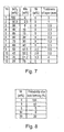
- Figure 7 shows one example of the mixing ratio (% by weight) of the powder and the thickness of the respective layer.
- the above described compact is temporally sintered, yielding a temporarily sintered body.
- the upholding part 40 of the electrode is inserted into the center opening of the temporally sintered body obtained in the fourth process and completely sintered.
- the sealing body 50 When using a functional gradient material with the mixing ratios shown in Figure 7 the sealing body 50 consists of 12 layers as is shown in Figure 9.
- the first layer contains only silicon dioxide, while the second to eighth layers and the twelfth layer consist of mixtures of silicon dioxide and molybdenum which were formed from the first powder mixtures.
- the ninth to eleventh layers are mixtures of silicon dioxide, molybdenum and nickel which were formed from the second powder mixtures.
- the layers have different thicknesses as is shown in Figure 7. However they are feasibly shown in Figure 9 with the same thickness.
- This temporarily sintered body is sintered for 10 minutes in a nonoxidizing atmosphere or in a vacuum of roughly 10 -2 Pa at 1750°C.
- the mixing ratio of nickel to molybdenum in Figure 7 is 5% by weight. However the mixing ratio of the nickel to the molybdenum was changed and these mixing ratios and the degree of formation of leaks were studied. Figure 8 shows the result.
- the upholding part 40 of the electrode is placed in the middle of the cylindrical casting mold.
- the cylindrical casting mold is gradually filled with first and second powder mixtures which have been mixed with an organic binder.
- the cylindrical casting mold is pressed from the outside. Thus a compact is obtained which is formed integrally with the upholding part 40 of the electrode.
- first powder mixtures are produced in which an electrically conductive inorganic material component, for example molybdenum powder, and a dielectric inorganic material component such as silicon dioxide powder, are mixed with different mixing ratios to one another.
- Chromium powder as the diffusion accelerator is mixed with at least one type of the first powder mixtures with a volumetric ratio of for example 5%, yielding second powder mixtures.
- the first powder mixtures and the second powder mixtures are mixed individually with an organic binder.
- a cylindrical casting mold is filled with the first powder mixtures such that the ratio of the molybdenum powder to the silicon dioxide powder changes gradually.
- the casting mold is next filled with the second powder mixtures and then filled with the first powder mixtures such that likewise the ratio of the molybdenum powder to the silicon dioxide powder changes gradually.
- the cylindrical casting mold is pressed from the outside. This yields a compact consisting of many layers.
- Figure 10 shows one example of the mixing ratio (% by weight) of the powder and the thickness of the respective layer.
- the above described compact is temporally sintered, yielding a temporarily sintered body.
- the upholding part 40 of the electrode is inserted into the center opening of the temporally sintered body.
- the sealing body 50 When using a functional gradient material with the mixing ratios shown in Figure 10 the sealing body 50 consists of 12 layers.
- the first layer contains only silicon dioxide, while the second to eighth layers and the twelfth layer consist of mixtures of silicon dioxide and molybdenum which were formed from the first powder mixtures.
- the ninth to eleventh layers are mixtures of silicon dioxide, molybdenum and chromium which were formed from the second powder mixtures.
- This temporarily sintered body is completely sintered for 10 minutes in a nonoxidizing atmosphere or in a vacuum of roughly 10 -2 Pa at 1750°C.
- an electrical insertion body for a tube lamp which is suitable for sealing the sealing tubes of a tube lamp, such as a mercury lamp, a metal halide lamp, a halogen lamp or the like.
Landscapes
- Vessels And Coating Films For Discharge Lamps (AREA)
Claims (4)
- Corps (70) d'insertion électrique pour une lampe tubulaire, destiné à sceller hermétiquement un tube d'étanchéité (12) qui est raccordé au tube à arc (11) de la lampe tubulaire, dans lequel un élément (40) de support de l'électrode est inséré dans l'ouverture centrale du corps d'obturation respectif (50) d'un matériau à gradient fonctionnel qui se compose d'un composant en matériau inorganique électriquement conducteur et d'un composant en matériau inorganique diélectrique, et qui prend la forme d'une colonne multicouche de telle sorte que le rapport des deux composants change graduellement dans la direction axiale,
caractérisé en ce que, dans la zone de frontière entre ledit corps d'étanchéité (50) et l'élément (40) de support de l'électrode, il est formé une zone de diffusion dans laquelle le composant en matériau inorganique électriquement conducteur qui forme le corps d'obturation (50), un composant métallique de l'élément (40) de support de l'électrode et un accélérateur (60) de diffusion sont diffusés les uns dans les autres, ce qui, à la température de frittage du matériau à gradient fonctionnel décrit au-dessus, accélère la diffusion du composant en matériau inorganique électriquement conducteur qui forme le corps d'obturation (50) et du composant métallique de l'élément (40) de support de l'électrode et
en ce que, de cette manière, l'élément (40) de support de l'électrode et l'intérieur de l'ouverture centrale du corps d'obturation (50) sont réunis l'un à l'autre. - Procédé de fabrication d'un corps d'insertion électrique pour une lampe tubulaire selon la revendication 1, caractérisé par les étapes de processus suivantes :un premier processus dans lequel des mélanges de poudres sont produits en mélangeant le composant en matériau inorganique électriquement conducteur avec le composant en matériau inorganique diélectrique ;un deuxième processus dans lequel les mélanges de poudres produits dans le premier processus sont mélangés à un liant organique avec lequel un moule cylindrique de moulage avec un composant en saillie pour réaliser une ouverture centrale est rempli, dans lequel le moule cylindrique de moulage est ensuite soumis à pression depuis l'extérieur et un compactage est obtenu ;un troisième processus dans lequel le compactage décrit ci-dessus est temporairement fritté et un corps temporairement fritté est ainsi obtenu ;un quatrième processus dans lequel la surface périphérique extérieure de l'élément de support respectif de l'électrode est enrobée d'un accélérateur de diffusion ; etun cinquième processus dans lequel l'élément de support de l'électrode qui a été obtenu dans le quatrième processus est inséré dans l'ouverture centrale du corps temporairement fritté obtenu lors du troisième processus, dans lequel ensuite ce corps temporairement fritté est fritté totalement, et dans lequel ainsi l'élément de support de l'électrode et l'intérieur de l'ouverture centrale du corps fritté totalement sont réunis l'un à l'autre.
- Procédé de fabrication d'un corps d'insertion électrique pour une lampe tubulaire selon la revendication 1, caractérisé par les étapes de processus suivantes :un premier processus dans lequel des mélanges de poudres sont produits en mélangeant le composant en matériau inorganique électriquement conducteur avec le composant en matériau inorganique diélectrique ;un deuxième processus dans lequel la surface périphérique extérieure de l'élément de support respectif de l'électrode est enrobé d'un accélérateur de diffusion ; etun troisième processus dans lequel l'élément de support de l'électrode obtenu dans le second processus est placé au centre d'un moule cylindrique de moulage, dans lequel de plus les mélanges de poudres produits dans le premier processus sont mélangés à un liant organique avec lequel le moule cylindrique de moulage est rempli, dans lequel ensuite le moule cylindrique de moulage est soumis à pression depuis l'extérieur et un compactage est obtenu ;un quatrième processus dans lequel le compactage décrit ci-dessus est temporairement fritté et un corps temporairement fritte est ainsi obtenu ;un cinquième processus dans lequel le corps temporairement fritté obtenu lors du quatrième processus est fritté totalement, et dans lequel ainsi l'élément de support de l'électrode et l'intérieur de l'ouverture centrale du corps fritté totalement sont réunis l'un à l'autre.
- Procédé de fabrication d'un corps d'insertion électrique pour une lampe tubulaire, procédé selon la revendication 2 ou 3, dans lequel
au lieu de l'enrobage de la surface périphérique extérieure de l'élément de support de l'électrode avec l'accélérateur de diffusion, le composant en matériau inorganique électriquement conducteur et le composant en matériau inorganique diélectrique dans lequel l'accélérateur de diffusion est mélangé sont mélangés l'un avec l'autre dans le premier processus, et dans lequel des mélanges de poudres sont ainsi obtenus.
Applications Claiming Priority (3)
| Application Number | Priority Date | Filing Date | Title |
|---|---|---|---|
| JP6928398 | 1998-03-05 | ||
| JP6928398 | 1998-03-05 | ||
| PCT/JP1999/001003 WO1999045570A1 (fr) | 1998-03-05 | 1999-03-03 | Corps d'entree de courant electrique, destine a une ampoule, et procede de fabrication associe |
Publications (3)
| Publication Number | Publication Date |
|---|---|
| EP1001453A1 EP1001453A1 (fr) | 2000-05-17 |
| EP1001453A4 EP1001453A4 (fr) | 2002-11-06 |
| EP1001453B1 true EP1001453B1 (fr) | 2004-09-22 |
Family
ID=13398153
Family Applications (1)
| Application Number | Title | Priority Date | Filing Date |
|---|---|---|---|
| EP99938013A Expired - Lifetime EP1001453B1 (fr) | 1998-03-05 | 1999-03-03 | Corps d'entree de courant electrique, destine a une ampoule, et procede de fabrication associe |
Country Status (4)
| Country | Link |
|---|---|
| US (1) | US6375533B1 (fr) |
| EP (1) | EP1001453B1 (fr) |
| DE (1) | DE69920373T2 (fr) |
| WO (1) | WO1999045570A1 (fr) |
Families Citing this family (17)
| Publication number | Priority date | Publication date | Assignee | Title |
|---|---|---|---|---|
| EP1043754B1 (fr) * | 1999-04-06 | 2004-05-26 | Ushiodenki Kabushiki Kaisha | Scellement pour lampes utilisant un matériau à gradient fonctionnel |
| JP2001015070A (ja) * | 1999-06-29 | 2001-01-19 | Ushio Inc | 放電ランプ |
| DE19961551A1 (de) * | 1999-12-20 | 2001-06-21 | Patent Treuhand Ges Fuer Elektrische Gluehlampen Mbh | Einschmelzfolie und zugehörige Lampe mit dieser Folie |
| CN1217372C (zh) * | 2000-06-26 | 2005-08-31 | 松下电器产业株式会社 | 放电灯的制造方法 |
| CN1615535A (zh) * | 2002-01-15 | 2005-05-11 | 皇家飞利浦电子股份有限公司 | 高压放电灯 |
| US7839089B2 (en) * | 2002-12-18 | 2010-11-23 | General Electric Company | Hermetical lamp sealing techniques and lamp having uniquely sealed components |
| US7132797B2 (en) * | 2002-12-18 | 2006-11-07 | General Electric Company | Hermetical end-to-end sealing techniques and lamp having uniquely sealed components |
| US7215081B2 (en) * | 2002-12-18 | 2007-05-08 | General Electric Company | HID lamp having material free dosing tube seal |
| US20060001346A1 (en) * | 2004-06-30 | 2006-01-05 | Vartuli James S | System and method for design of projector lamp |
| US7358666B2 (en) | 2004-09-29 | 2008-04-15 | General Electric Company | System and method for sealing high intensity discharge lamps |
| US7432657B2 (en) * | 2005-06-30 | 2008-10-07 | General Electric Company | Ceramic lamp having shielded niobium end cap and systems and methods therewith |
| US7615929B2 (en) | 2005-06-30 | 2009-11-10 | General Electric Company | Ceramic lamps and methods of making same |
| US7852006B2 (en) | 2005-06-30 | 2010-12-14 | General Electric Company | Ceramic lamp having molybdenum-rhenium end cap and systems and methods therewith |
| US7378799B2 (en) * | 2005-11-29 | 2008-05-27 | General Electric Company | High intensity discharge lamp having compliant seal |
| US8299709B2 (en) * | 2007-02-05 | 2012-10-30 | General Electric Company | Lamp having axially and radially graded structure |
| DE102009008636A1 (de) * | 2009-02-12 | 2010-08-19 | Osram Gesellschaft mit beschränkter Haftung | Hochdruckentladungslampe |
| TWI435368B (zh) * | 2011-11-10 | 2014-04-21 | Ind Tech Res Inst | 氣體放電燈及其製作方法 |
Family Cites Families (13)
| Publication number | Priority date | Publication date | Assignee | Title |
|---|---|---|---|---|
| EP0028885B1 (fr) * | 1979-11-12 | 1983-05-25 | Thorn Emi Plc | Cermet électriquement conducteur, sa préparation et son utilisation |
| JPH0791610B2 (ja) * | 1985-06-17 | 1995-10-04 | 日本電装株式会社 | 非酸化物セラミックヒータ用金属ロー材 |
| JPS63160662U (fr) * | 1987-04-10 | 1988-10-20 | ||
| US5742123A (en) * | 1992-07-09 | 1998-04-21 | Toto Ltd. | Sealing structure for light-emitting bulb assembly and method of manufacturing same |
| WO1994006947A1 (fr) * | 1992-09-24 | 1994-03-31 | Toto Ltd. | Materiau a gradient fonctionnel et procede de production |
| DE4242122A1 (de) * | 1992-12-14 | 1994-06-16 | Patent Treuhand Ges Fuer Elektrische Gluehlampen Mbh | Verfahren zur Herstellung einer vakuumdichten Abdichtung zwischen einem keramischen und einem metallischen Partner, insbesondere zur Anwendung bei der Herstellung eines Entladungsgefäßes für eine Lampe, sowie damit hergestellte Entladungsgefäße und Lampen |
| DE69324790T2 (de) * | 1993-02-05 | 1999-10-21 | Ngk Insulators, Ltd. | Keramisches Entladungsgefäss für Hochdruckentladungslampe und Herstellungsverfahren derselben und damit verbundene Dichtungsmaterialien |
| DE4338377A1 (de) * | 1993-11-10 | 1995-05-11 | Patent Treuhand Ges Fuer Elektrische Gluehlampen Mbh | Metallhalogenidentladungslampe mit keramischem Entladungsgefäß und Herstellverfahren für eine derartige Lampe |
| JPH09125186A (ja) * | 1995-10-30 | 1997-05-13 | Toto Ltd | 傾斜機能材料、傾斜機能材料を用いた放電灯の封止部材及び傾斜機能材料の製造方法 |
| JP3151166B2 (ja) * | 1996-05-16 | 2001-04-03 | 日本碍子株式会社 | 高圧放電灯およびその製造方法 |
| JP3396142B2 (ja) | 1996-12-26 | 2003-04-14 | ウシオ電機株式会社 | 高圧放電ランプ |
| US6271627B1 (en) * | 1997-04-11 | 2001-08-07 | Ushiodenki Kabushiki Kaisha | Sealing body having a shielding layer for hermetically sealing a tube lamp |
| JP3993667B2 (ja) * | 1997-06-30 | 2007-10-17 | ウシオ電機株式会社 | 管球の閉塞部構造体 |
-
1999
- 1999-03-03 EP EP99938013A patent/EP1001453B1/fr not_active Expired - Lifetime
- 1999-03-03 DE DE69920373T patent/DE69920373T2/de not_active Expired - Lifetime
- 1999-03-03 WO PCT/JP1999/001003 patent/WO1999045570A1/fr active IP Right Grant
- 1999-03-03 US US09/403,789 patent/US6375533B1/en not_active Expired - Lifetime
Also Published As
| Publication number | Publication date |
|---|---|
| US6375533B1 (en) | 2002-04-23 |
| WO1999045570A1 (fr) | 1999-09-10 |
| DE69920373D1 (de) | 2004-10-28 |
| DE69920373T2 (de) | 2005-11-17 |
| EP1001453A1 (fr) | 2000-05-17 |
| EP1001453A4 (fr) | 2002-11-06 |
Similar Documents
| Publication | Publication Date | Title |
|---|---|---|
| EP1001453B1 (fr) | Corps d'entree de courant electrique, destine a une ampoule, et procede de fabrication associe | |
| US5810635A (en) | High-pressure discharge lamp, method of its manufacture, and sealing material used with the method and the resulting lamp | |
| EP0887837B1 (fr) | Ampoule céramique, lampe munie d'une telle ampoule, et procédé de fabrication de tels dispositifs | |
| US5552670A (en) | Method of making a vacuum-tight seal between a ceramic and a metal part, sealed structure, and discharge lamp having the seal | |
| US6232719B1 (en) | High-pressure discharge lamp and method for manufacturing same | |
| US5404077A (en) | High-pressure discharge lamp | |
| US6194832B1 (en) | Metal halide lamp with aluminum gradated stacked plugs | |
| EP0987736B1 (fr) | Lampe céramique | |
| US6169366B1 (en) | High pressure discharge lamp | |
| JP4231380B2 (ja) | 電球及びそれに用いられる電流導体 | |
| JP3271601B2 (ja) | 管球用電気導入体およびその製造方法 | |
| JP3926211B2 (ja) | 高圧水銀灯および高圧水銀灯用封止材 | |
| JP3419275B2 (ja) | 放電ランプのシール方法 | |
| JP3736710B2 (ja) | 管球用電気導入体 | |
| US6850009B2 (en) | Joined body and high pressure discharge lamp | |
| EP0926700B1 (fr) | Electrode pour lampe à décharge haute pression | |
| US8299709B2 (en) | Lamp having axially and radially graded structure | |
| JPH10289691A (ja) | 傾斜機能材料を使った閉塞体 | |
| JPH0660855A (ja) | 高光強度電灯光源の耐火性金属部品を溶接するための溶接補助材 | |
| JPH11260315A (ja) | 管球の閉塞部構造体 | |
| JPH0719574B2 (ja) | 金属蒸気放電灯およびその製造方法 | |
| JPH11307056A (ja) | 管球の閉塞部構造体 |
Legal Events
| Date | Code | Title | Description |
|---|---|---|---|
| PUAI | Public reference made under article 153(3) epc to a published international application that has entered the european phase |
Free format text: ORIGINAL CODE: 0009012 |
|
| 17P | Request for examination filed |
Effective date: 19991105 |
|
| AK | Designated contracting states |
Kind code of ref document: A1 Designated state(s): DE GB NL |
|
| A4 | Supplementary search report drawn up and despatched | ||
| AK | Designated contracting states |
Kind code of ref document: A4 Designated state(s): DE GB NL |
|
| A4 | Supplementary search report drawn up and despatched |
Effective date: 20021106 |
|
| GRAP | Despatch of communication of intention to grant a patent |
Free format text: ORIGINAL CODE: EPIDOSNIGR1 |
|
| GRAS | Grant fee paid |
Free format text: ORIGINAL CODE: EPIDOSNIGR3 |
|
| GRAA | (expected) grant |
Free format text: ORIGINAL CODE: 0009210 |
|
| AK | Designated contracting states |
Kind code of ref document: B1 Designated state(s): DE GB NL |
|
| REG | Reference to a national code |
Ref country code: GB Ref legal event code: FG4D |
|
| REF | Corresponds to: |
Ref document number: 69920373 Country of ref document: DE Date of ref document: 20041028 Kind code of ref document: P |
|
| PLBE | No opposition filed within time limit |
Free format text: ORIGINAL CODE: 0009261 |
|
| STAA | Information on the status of an ep patent application or granted ep patent |
Free format text: STATUS: NO OPPOSITION FILED WITHIN TIME LIMIT |
|
| 26N | No opposition filed |
Effective date: 20050623 |
|
| PGFP | Annual fee paid to national office [announced via postgrant information from national office to epo] |
Ref country code: DE Payment date: 20160223 Year of fee payment: 18 |
|
| PGFP | Annual fee paid to national office [announced via postgrant information from national office to epo] |
Ref country code: GB Payment date: 20160302 Year of fee payment: 18 Ref country code: NL Payment date: 20160210 Year of fee payment: 18 |
|
| REG | Reference to a national code |
Ref country code: DE Ref legal event code: R119 Ref document number: 69920373 Country of ref document: DE |
|
| REG | Reference to a national code |
Ref country code: NL Ref legal event code: MM Effective date: 20170401 |
|
| GBPC | Gb: european patent ceased through non-payment of renewal fee |
Effective date: 20170303 |
|
| PG25 | Lapsed in a contracting state [announced via postgrant information from national office to epo] |
Ref country code: DE Free format text: LAPSE BECAUSE OF NON-PAYMENT OF DUE FEES Effective date: 20171003 Ref country code: NL Free format text: LAPSE BECAUSE OF NON-PAYMENT OF DUE FEES Effective date: 20170401 |
|
| PG25 | Lapsed in a contracting state [announced via postgrant information from national office to epo] |
Ref country code: GB Free format text: LAPSE BECAUSE OF NON-PAYMENT OF DUE FEES Effective date: 20170303 |