EP1001167B1 - Electromagnetic pump - Google Patents
Electromagnetic pump Download PDFInfo
- Publication number
- EP1001167B1 EP1001167B1 EP99122025A EP99122025A EP1001167B1 EP 1001167 B1 EP1001167 B1 EP 1001167B1 EP 99122025 A EP99122025 A EP 99122025A EP 99122025 A EP99122025 A EP 99122025A EP 1001167 B1 EP1001167 B1 EP 1001167B1
- Authority
- EP
- European Patent Office
- Prior art keywords
- plunger
- yoke
- electromagnetic pump
- cylinder
- plastic mold
- Prior art date
- Legal status (The legal status is an assumption and is not a legal conclusion. Google has not performed a legal analysis and makes no representation as to the accuracy of the status listed.)
- Expired - Lifetime
Links
Images


Classifications
-
- F—MECHANICAL ENGINEERING; LIGHTING; HEATING; WEAPONS; BLASTING
- F04—POSITIVE - DISPLACEMENT MACHINES FOR LIQUIDS; PUMPS FOR LIQUIDS OR ELASTIC FLUIDS
- F04B—POSITIVE-DISPLACEMENT MACHINES FOR LIQUIDS; PUMPS
- F04B17/00—Pumps characterised by combination with, or adaptation to, specific driving engines or motors
- F04B17/03—Pumps characterised by combination with, or adaptation to, specific driving engines or motors driven by electric motors
- F04B17/04—Pumps characterised by combination with, or adaptation to, specific driving engines or motors driven by electric motors using solenoids
- F04B17/046—Pumps characterised by combination with, or adaptation to, specific driving engines or motors driven by electric motors using solenoids the fluid flowing through the moving part of the motor
-
- F—MECHANICAL ENGINEERING; LIGHTING; HEATING; WEAPONS; BLASTING
- F01—MACHINES OR ENGINES IN GENERAL; ENGINE PLANTS IN GENERAL; STEAM ENGINES
- F01M—LUBRICATING OF MACHINES OR ENGINES IN GENERAL; LUBRICATING INTERNAL COMBUSTION ENGINES; CRANKCASE VENTILATING
- F01M1/00—Pressure lubrication
- F01M1/02—Pressure lubrication using lubricating pumps
- F01M2001/0207—Pressure lubrication using lubricating pumps characterised by the type of pump
- F01M2001/0223—Electromagnetic pumps
Definitions
- the plunger 2 reciprocates in the manner as mentioned previously.
- the discharge valve 12 is closed and the inlet valve 11 is opened, whereby oil is drawn into a pump chamber (a space between the discharge valve 12 and the inlet valve 11) from the nipple 6 and the center hole of the plunger 2, by way of a gap between the inlet valve 11 and the valve seat 24.
- the discharge valve 12 is opened and the inlet valve 11 is closed, whereby oil is forced out to an oil flow channel of the inner yoke 4 from the pump chamber, by way of the space between the discharge valve 12 and the valve seat 7.
- An engine control unit controls a pulse current which is to be applied to the coil 16 in response to a signal output from a sensor for detecting the working state of the engine, thus controlling the amount of engine oil to be supplied.
- the present invention provides an electromagnetic pump, in which a plunger is reciprocated within a cylinder by means of the restoration force of a spring and electromagnetic force acting on a magnetic circuit, comprising an inner yoke and the plunger, so as to reduce a magnetic gap between the inner yoke and the plunger, wherein the stroke of the plunger is limited by two planes of two members disposed so as to opposite each other with the cylinder interposed therebetween.
- a protuberance is formed on a plastic mold covering a coil for applying a magnetomotive force to the plunger, and the protuberance is deformed to fix the plastic mold by means of fixing an end yoke to an outer yoke by caulking while the plastic mold is housed within the space defined by the end yoke and an outer yoke, which constitute the magnetic circuit.
- FIG. 1 is a cross-sectional view showing an electromagnetic pump to be used as a separate oil pump of an engine according to a first embodiment of the present invention.
- An illustrated plunger 2 is slidably fitted into a cylinder 1 formed from non-magnetic material, such as aluminum or brass, and is forced rightward by means of a compression coil spring 8.
- An inner yoke 3 opposite the plunger 2 is pressingly fitted into an end yoke 4, and the end yoke 4 is fixed to an outer yoke 5 by means of caulking.
- a nipple 6 pressingly-fitted into the outer yoke 5 is in close proximity to the plunger 2.
- the plunger 2, the inner yoke 3, the end yoke 4, the outer yoke 5, and the nipple 6 are formed from magnetic material and constitute a magnetic circuit.
- the stroke of the plunger 2 is expressed by X-Y.
- the accuracy of the stroke of the plunger 2 is affected by only the dimensional accuracy of the cylinder 1 and the dimensional accuracy of the plunger 2.
- the dimensional accuracy of length of the cylinder 1 and the dimensional accuracy of length of the plunger 2 can be readily improved by means of turning. Accordingly, the accuracy of the stroke of the plunger 2 can be readily improved.
- the method of actuating the electromagnetic pump of the present embodiment is the same as that which has already been described in connection with the conventional example.
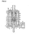
- FIG. 2 is a cross-sectional view showing an electromagnetic pump used as a separating oil pump of an engine according to a second embodiment of the present invention.
- a protuberance 23 is provided on the face of the plastic mold 14 facing the outer yoke 5.
- the height of the protuberance 23 is set such that a portion of the protuberance 23 is deformed when the edge of the outer yoke 5 is locked to the end yoke 4 by caulking while the plastic mold 14 is housed in the space between the end yoke 4 and the outer yoke 5.
- the protuberance is formed on the end face of the plastic mold.
- the edge of the outer yoke 5 is locked to the end yoke 4 by caulking while the plastic mold 14 is housed in the space between the end yoke 4 and the outer yoke 5, the protuberance is deformed, thus locking the plastic mold 14. Accordingly, the necessity for the O-ring can be reduced, and the number of components of the assembly can be diminished.
Landscapes
- Engineering & Computer Science (AREA)
- Physics & Mathematics (AREA)
- Fluid Mechanics (AREA)
- Mechanical Engineering (AREA)
- General Engineering & Computer Science (AREA)
- Electromagnetic Pumps, Or The Like (AREA)
- Details Of Reciprocating Pumps (AREA)
- Magnetically Actuated Valves (AREA)
Description
- The present invention relates to an electromagnetic pump, and more particularly, to an electromagnetic pump suitable for use in a separating oil pump of a two-cycle engine.
- An electromagnetic pump-which applies a pulse current to a solenoid, to thereby reciprocate a plunger and draw oil in and force oil out-has conventionally been employed as a separate oil pump of a two-cycle engine. FIG. 3 shows an example of such a conventional electromagnetic pump. An illustrated
plunger 2 is slidably fitted into acylinder 1 formed from non-magnetic material, such as aluminum or brass, and is forced rightward by means of restoration force of acompression coil spring 8. - An
inner yoke 3 opposite theplunger 2 is pressingly fitted into anend yoke 4, and theend yoke 4 is fixed to anouter yoke 5 by means of caulking. Anipple 6 pressingly-fitted into theouter yoke 5 is in close proximity to theplunger 2. Theplunger 2, theinner yoke 3, theend yoke 4, theouter yoke 5, and thenipple 6 are formed from magnetic material and constitute a magnetic circuit. - A
coil 16, which is wound around aplastic coil bobbin 13 and applies magnetomotive force to the magnetic circuit, is covered with thecoil bobbin 13 and aplastic mold 14. Theplastic mold 14 is housed in the space which surrounds thecylinder 1 and which is defined by theend yoke 4 and theouter yoke 5. The edge of theouter yoke 5 is locked to theend yoke 4 by means of caulking, while theplastic mold 14 remains in pressing contact with theend yoke 4 by means of acushion member 23 interposed between theouter yoke 5 and theplastic mold 14. Power is supplied to thecoil 16 from an electrode 15 embedded in theplastic mold 14. - A
valve seat 7 is pressed into theinner yoke 3 while being properly positioned. A discharge valve 12 is forced by the compression coil spring 10 so as to close a flow channel of thevalve seat 7. Avalve seat 24 is pressingly fitted into theplunger 2. An inlet valve 11 is forced by acompression coil spring 9 so as to close a flow channel of thevalve seat 24. - An O-
ring 19 hermetically seals a space between theinner yoke 3 and thecylinder 1, and an O-ring 17 hermetically seals a space between thenipple 6 and thecylinder 1. Aspacer 20 interposed between thenipple 6 and theplunger 2 controls the maximum magnetic gap between theplunger 2 and theinner yoke 3; i.e., a plunger stroke. - In the electromagnetic pump having the foregoing configuration, when an electric current flows through the
coil 16, a magnetic field develops in the magnetic gap between theplunger 2 and theinner yoke 3, as a result of which theplunger 2 is attracted by theinner yoke 3 against the restoration force of thecompression coil spring 8. When the electric current flowing through thecoil 16 is shut off, theplunger 2 is separated from theinner yoke 3 and is brought into pressing contact with thespacer 20, by means of restoration force of thecompression coil spring 8. - The
plunger 2 reciprocates in the manner as mentioned previously. When theplunger 2 is moved rightward the discharge valve 12 is closed and the inlet valve 11 is opened, whereby oil is drawn into a pump chamber (a space between the discharge valve 12 and the inlet valve 11) from thenipple 6 and the center hole of theplunger 2, by way of a gap between the inlet valve 11 and thevalve seat 24. In contrast, when theplunger 2 is moved leftward, the discharge valve 12 is opened and the inlet valve 11 is closed, whereby oil is forced out to an oil flow channel of theinner yoke 4 from the pump chamber, by way of the space between the discharge valve 12 and thevalve seat 7. An engine control unit controls a pulse current which is to be applied to thecoil 16 in response to a signal output from a sensor for detecting the working state of the engine, thus controlling the amount of engine oil to be supplied. - The flow rate of the electromagnetic pump is determined from the number of pulses of the electric current and plunger strokes. The stroke of the
plunger 2 corresponds to a difference between the distance between the end face of thespacer 20 and the end face of theinner yoke 3 and the distance between the end face of theplunger 2 and a step of the same. Tolerances of many parts contribute to the distance between the end face of thespacer 20 and the end face of theinner yoke 3. - More specifically, tolerances stemming from the pressing of the
nipple 6 into theouter yoke 5, fixing of theend yoke 4 to theouter yoke 5 by caulking, and dimensional tolerances of thenipple 6, thecylinder 1, theplunger 2, thespacer 20, and theinner yoke 5, contribute to the distance. - In terms of electrical conditions under which the
plunger 2 can be actuated, the diameter of the plunger is limited to a value of Ø6 to Ø7. If the diameter of the plunger is made smaller than this range, the plunger cannot be actuated. Further, in order to diminish power consumption, the stroke of theplunger 2 must be made smaller. In consideration of the amount of oil required to be delivered, the stroke of theplunger 2 assumes a value of 0.5 mm or less for a two-cycle engine. If the tolerance of flow rate is reduced to 10% or less, variations in the stroke of theplunger 2 must be held to ±0.05 mm or less. Thus, in order to reduce the tolerance of stroke of the plunger, thespacer 20 must be prepared in various sizes, and adjustment of stroke requires a lot of time. - Further, since the
compression coil spring 9 for constraining the inlet valve 11 is disposed within the pump chamber, the dead volume of the pump chamber becomes large, thereby resulting in a decrease in compression ratio and a drop in air displacement capability. If the air displacement capability of the pump is too small, in the worst case the pump fails to supply oil because of an air-lock phenomenon. - JP 06-010831 A discusses a solenoid pump. The solenoid pump consists of a pump body and a magnetic force supply source. The pump body comprises a retaining cylinder, which consists of a non-magnetic substance cylinder section and a magnetic substance cylinder section, a suction cylinder section and a discharge cylinder section, which are arranged on both ends of the retaining cylinder, and a piston receiver, which is arranged beside the discharge cylinder section within the retaining cylinder and has a valve retainer positioned beside the discharge cylinder section, and a magnetic substance piston having a valve retainer beside the piston receiver. The stroke of the piston is limited by the length of the retaining cylinder, an end face of the suction cylinder section, and end face of the piston receiver and the length of the piston, wherein each end face of the suction cylinder section or the piston receiver is different from the plane contacting the end face of the retaining cylinder. The piston stroke is defined by four parts, i.e. the piston, the retaining cylinder, the suction cylinder, and the piston receiver.
- The present invention has been conceived in view of the foregoing problems of the prior art, and an object of the present invention is to provide an electromagnetic pump capable of readily and precisely determining the stroke of a plunger. Another object of the present invention is to provide an electromagnetic pump having large air displacement capability.
- To these ends, the present invention provides an electromagnetic pump, in which a plunger is reciprocated within a cylinder by means of the restoration force of a spring and electromagnetic force acting on a magnetic circuit, comprising an inner yoke and the plunger, so as to reduce a magnetic gap between the inner yoke and the plunger, wherein
the stroke of the plunger is limited by two planes of two members disposed so as to opposite each other with the cylinder interposed therebetween. - Preferably, one of the two members corresponds to a ring-shaped spacer, and the spacer is brought into pressing contact with the cylinder by means of a wave washer.
- Preferably, a fluid inlet channel is formed within the plunger; a spring receiving section which extends to the inside of the inlet channel of the plunger is formed in the inlet valve which opens or closes the inlet channel; and a spring for constraining the inlet valve is locked to the spring receiving section.
- Preferably, a protuberance is formed on a plastic mold covering a coil for applying a magnetomotive force to the plunger, and the protuberance is deformed to fix the plastic mold by means of fixing an end yoke to an outer yoke by caulking while the plastic mold is housed within the space defined by the end yoke and an outer yoke, which constitute the magnetic circuit.
-
- FIG. 1 is a cross-sectional view showing an electromagnetic pump according to a first embodiment of the present invention;
- FIG. 2 is a cross-sectional view showing an electromagnetic pump according to a second embodiment of the present invention; and
- FIG. 3 is a cross-sectional view showing an example of an conventional electromagnetic pump.
- Preferred embodiments of the present invention will be described hereinbelow by reference to the accompanying drawings. FIG. 1 is a cross-sectional view showing an electromagnetic pump to be used as a separate oil pump of an engine according to a first embodiment of the present invention. An illustrated
plunger 2 is slidably fitted into acylinder 1 formed from non-magnetic material, such as aluminum or brass, and is forced rightward by means of acompression coil spring 8. - An
inner yoke 3 opposite theplunger 2 is pressingly fitted into anend yoke 4, and theend yoke 4 is fixed to anouter yoke 5 by means of caulking. Anipple 6 pressingly-fitted into theouter yoke 5 is in close proximity to theplunger 2. Theplunger 2, theinner yoke 3, theend yoke 4, theouter yoke 5, and thenipple 6 are formed from magnetic material and constitute a magnetic circuit. - A
coil 16, which is wound around aplastic coil bobbin 13 and applies magnetomotive force to the magnetic circuit, is covered with thecoil bobbin 13 and aplastic mold 14. While theplastic mold 14 is housed in the space which surrounds thecylinder 1 and is defined by theend yoke 4 and theouter yoke 5, the edge of theouter yoke 5 is locked to theend yoke 4 by means of caulking. Power is supplied to thecoil 16 from an electrode 15 embedded in theplastic mold 14. - A
valve seat 7 is pressed into theinner yoke 3 while being properly positioned. A discharge valve 12 is forced so as to close a flow channel of thevalve seat 7 by means of the compression coil spring 10. An inlet valve 11 is forced so as to close a flow channel of the valve seat which is formed within theplunger 2 by means of acompression coil spring 9. - An O-
ring 19 hermetically seals a space between theinner yoke 3 and thecoil bobbin 13, and an O-ring 17 hermetically seals a space between thenipple 6 and thecoil bobbin 13. Further, an O-ring 18 hermetically seals a space between thecylinder 1 and thecoil bobbin 13. Aspacer 20 whose opposite sides are flat is formed into a ring shape and is forced by means of awave washer 21 interposed between thenipple 6 and thespacer 20, to thereby bring the left end face of thecylinder 1 into pressing contact with theinner yoke 3, as well as to lock the step of theplunger 2 so as to limit the stroke of theplunger 2. - As shown in the drawing, when the length of the
cylinder 1 is taken as X, and the illustrated distance between the end face of theplunger 2 and a step of the same is taken as Y, the stroke of theplunger 2 is expressed by X-Y. The accuracy of the stroke of theplunger 2 is affected by only the dimensional accuracy of thecylinder 1 and the dimensional accuracy of theplunger 2. The dimensional accuracy of length of thecylinder 1 and the dimensional accuracy of length of theplunger 2 can be readily improved by means of turning. Accordingly, the accuracy of the stroke of theplunger 2 can be readily improved. The method of actuating the electromagnetic pump of the present embodiment is the same as that which has already been described in connection with the conventional example. - FIG. 2 is a cross-sectional view showing an electromagnetic pump used as a separating oil pump of an engine according to a second embodiment of the present invention. In place of the O-
ring 22 used in the first embodiment, aprotuberance 23 is provided on the face of theplastic mold 14 facing theouter yoke 5. The height of theprotuberance 23 is set such that a portion of theprotuberance 23 is deformed when the edge of theouter yoke 5 is locked to theend yoke 4 by caulking while theplastic mold 14 is housed in the space between theend yoke 4 and theouter yoke 5. Although in the second embodiment theprotuberance 23 is formed on the face of theplastic mold 14 facing theouter yoke 5, theprotuberance 23 may be provided on the face of theplastic mold 14 facing theend yoke 4, or the protuberances may be provided on both the face of theplastic mold 14 facing theouter yoke 5 and theend yoke 4. Further, theprotuberance 23 may be provided in one spot or in the form of a continuous raised ring. - A spring receiving section, which extends into the inside of an inlet channel of the
plunger 2, is formed in the inlet valve 11. Thecompression coil spring 9 for constraining the inlet valve 11 is locked in the spring receiving section. In other respects, the electromagnetic pump according to the present embodiment is identical in structure with the electromagnetic pump according to the first embodiment. The second embodiment yields the same advantageous results as those yielded in the first embodiment. Moreover, in the electromagnetic pump of the second embodiment, the dead volume of the pump chamber becomes smaller, thus increasing the air displacement capability of the electromagnetic pump. - Although the embodiments have described a case where the present invention is applied to a separating oil pump of the engine, the present invention can also be applied to another electromagnetic pump such as a fuel supply pump for use with a burner.
- In the electromagnetic pump of the present invention, the accuracy of stroke of the plunger cannot be affected by the caulked state of the outer yoke or the dimensional accuracy of parts. The accuracy of stroke of the plunger is affected by solely the dimensional accuracy of the plunger and the cylinder. The dimensional accuracies of the cylinder and the plunger in the longitudinal direction can be readily improved by means of turning, and hence the accuracy of stroke of the plunger can be easily improved.
- In the electromagnetic pump of the present invention, the dead volume of the pump chamber is reduced, and the air displacement capability of the pump can be improved.
- In the electromagnetic pump, the protuberance is formed on the end face of the plastic mold. When the edge of the
outer yoke 5 is locked to theend yoke 4 by caulking while theplastic mold 14 is housed in the space between theend yoke 4 and theouter yoke 5, the protuberance is deformed, thus locking theplastic mold 14. Accordingly, the necessity for the O-ring can be reduced, and the number of components of the assembly can be diminished.
Claims (4)
- An electromagnetic pump, in which a plunger (2) is reciprocated within a cylinder (1) by means of the restoration force of a spring (8) and electromagnetic force acting on a magnetic circuit, comprising an inner yoke (3) and the plunger (2), so as to reduce a magnetic gap between the inner yoke (3) and the plunger (2),
characterized in that
the stroke of the plunger (2) is limited by respective planes of two members (3, 20) disposed so as to be opposite each other with the cylinder (1) interposed therebetween, and
in that the plunger (2) has a step that limits the stroke of the plunger (2). - The electromagnetic pump as defined in claim 1, wherein one of the two members (3, 20) corresponds to a ring-shaped spacer (20), and the spacer (20) is brought into pressing contact with the cylinder (1) by means of a wave washer (21).
- The electromagnetic pump as defined in claim 1 or 2, wherein a fluid inlet channel is formed within the plunger (2); a spring receiving section which extends to the inside of the inlet channel of the plunger (2) is formed in the inlet valve (11) which opens or closes the inlet channel; and a spring (9) for constraining the inlet valve (11) is locked to the spring receiving section.
- The electromagnetic pump as defined in any one of claims 1 through 3, wherein a protuberance (23) is formed on a plastic mold (14) covering a coil (16) for applying a magnetomotive force to the plunger (2), and the protuberance (23) is deformed to fix the plastic mold (14) by means of fixing an end yoke (4) to an outer yoke (5) by caulking while the plastic mold (14) is housed within the space defined by the end yoke (4) and an outer yoke (5), which constitute the magnetic circuit.
Applications Claiming Priority (2)
| Application Number | Priority Date | Filing Date | Title |
|---|---|---|---|
| JP32325398 | 1998-11-13 | ||
| JP32325398A JP4203160B2 (en) | 1998-11-13 | 1998-11-13 | Electromagnetic pump |
Publications (3)
| Publication Number | Publication Date |
|---|---|
| EP1001167A2 EP1001167A2 (en) | 2000-05-17 |
| EP1001167A3 EP1001167A3 (en) | 2000-11-15 |
| EP1001167B1 true EP1001167B1 (en) | 2007-01-10 |
Family
ID=18152732
Family Applications (1)
| Application Number | Title | Priority Date | Filing Date |
|---|---|---|---|
| EP99122025A Expired - Lifetime EP1001167B1 (en) | 1998-11-13 | 1999-11-12 | Electromagnetic pump |
Country Status (4)
| Country | Link |
|---|---|
| US (1) | US6273689B1 (en) |
| EP (1) | EP1001167B1 (en) |
| JP (1) | JP4203160B2 (en) |
| DE (1) | DE69934759T2 (en) |
Families Citing this family (17)
| Publication number | Priority date | Publication date | Assignee | Title |
|---|---|---|---|---|
| KR100444817B1 (en) * | 2000-03-29 | 2004-08-18 | 주식회사 만도 | Solenoid valve for brake traction control system |
| DE60126056T2 (en) * | 2001-01-24 | 2007-07-12 | Mikuni Corp. | Fuel supply system |
| ITMI20010419A1 (en) * | 2001-03-01 | 2002-09-01 | Inc Dell Orto S P A | PUMP CONTROLLED BY ELECTROMAGNET |
| ITMI20020271U1 (en) * | 2002-05-23 | 2003-11-24 | C E M E Engineering S P A | IMPROVED ELECTRIC PUMP |
| JP4279527B2 (en) * | 2002-09-13 | 2009-06-17 | 株式会社ミクニ | Electromagnetic pump |
| US7150606B2 (en) * | 2003-10-28 | 2006-12-19 | Motor Components Llc | Electromagnetic fuel pump |
| KR20050094005A (en) * | 2004-03-17 | 2005-09-26 | 삼성광주전자 주식회사 | Linear compressor |
| EP2122167B1 (en) | 2007-03-15 | 2011-02-23 | Ceme S.p.A. | Hydraulic-electromagnetic motor pump with floating piston |
| KR200446440Y1 (en) * | 2008-05-09 | 2009-10-29 | 성신하스코 주식회사 | The solenoid pump where becomes the secret maintenance |
| JP5401175B2 (en) * | 2009-06-03 | 2014-01-29 | 浜名湖電装株式会社 | Electromagnetic solenoid device |
| US8783229B2 (en) | 2010-06-07 | 2014-07-22 | Caterpillar Inc. | Internal combustion engine, combustion charge formation system, and method |
| JP6229249B2 (en) * | 2012-08-06 | 2017-11-15 | 株式会社リコー | Valve failure detection device |
| ES1123905Y (en) * | 2014-08-19 | 2015-01-23 | Teylor Intelligent Processes Sl Empresa | Magnetic system for waterproof chamber pump |
| CN104314804A (en) * | 2014-09-26 | 2015-01-28 | 天纳克(苏州)排放系统有限公司 | Plunger pump and application thereof |
| SE1550049A1 (en) * | 2015-01-21 | 2016-07-22 | Osakeyhtiö Skf Ab | System, method & computer program product |
| JP6253623B2 (en) * | 2015-09-14 | 2017-12-27 | 本田技研工業株式会社 | Fuel shut-off valve |
| DK179750B1 (en) | 2017-12-13 | 2019-05-07 | Hans Jensen Lubricators A/S | Large slow-running two-stroke engine and method of lubri-cating such engine, as well as an injector with an electric pumping system for such engine and method |
Family Cites Families (11)
| Publication number | Priority date | Publication date | Assignee | Title |
|---|---|---|---|---|
| US2393237A (en) * | 1942-05-07 | 1946-01-22 | Richard T Cornelius | Motor pump unit |
| GB1102555A (en) * | 1964-03-14 | 1968-02-07 | Eberspaecher Walter | Electromagnetically-actuated reciprocating piston pumps for liquids |
| GB1484674A (en) * | 1974-12-03 | 1977-09-01 | British Leyland Uk Ltd | Pump for liquids |
| US4306842A (en) * | 1978-06-28 | 1981-12-22 | Jidosha Kiki Co., Ltd. | Electromagnetic pumps |
| US4643653A (en) * | 1984-10-15 | 1987-02-17 | Jidosha Kiki Co., Ltd. | Electromagnetic pump |
| JPS61126385A (en) * | 1984-11-22 | 1986-06-13 | Sawafuji Electric Co Ltd | Vibration type compressor |
| DE3719460A1 (en) * | 1986-07-03 | 1988-01-07 | Erich Becker | Method for driving a pump's pumping element connected to an oscillating-armature drive, and pump working according to it |
| JPH0199981U (en) * | 1987-12-25 | 1989-07-05 | ||
| US5073095A (en) * | 1990-04-10 | 1991-12-17 | Purolator Product Company | Whisper quiet electromagnetic fluid pump |
| JPH0610831A (en) * | 1992-06-26 | 1994-01-21 | Nippon Steel Corp | Solenoid pump |
| IT1299987B1 (en) * | 1998-04-27 | 2000-04-04 | Magneti Marelli Spa | VOLUMETRIC PUMP. |
-
1998
- 1998-11-13 JP JP32325398A patent/JP4203160B2/en not_active Expired - Fee Related
-
1999
- 1999-11-10 US US09/437,969 patent/US6273689B1/en not_active Expired - Fee Related
- 1999-11-12 EP EP99122025A patent/EP1001167B1/en not_active Expired - Lifetime
- 1999-11-12 DE DE69934759T patent/DE69934759T2/en not_active Expired - Lifetime
Also Published As
| Publication number | Publication date |
|---|---|
| DE69934759D1 (en) | 2007-02-22 |
| EP1001167A2 (en) | 2000-05-17 |
| DE69934759T2 (en) | 2007-10-11 |
| US6273689B1 (en) | 2001-08-14 |
| JP2000145623A (en) | 2000-05-26 |
| EP1001167A3 (en) | 2000-11-15 |
| JP4203160B2 (en) | 2008-12-24 |
Similar Documents
| Publication | Publication Date | Title |
|---|---|---|
| EP1001167B1 (en) | Electromagnetic pump | |
| JP4022857B2 (en) | Solenoid valve device | |
| JP3757817B2 (en) | Solenoid valve device | |
| EP0140048B1 (en) | Electrically controlled pressure transducer valve | |
| US20040262557A1 (en) | Magnetic actuator and method | |
| US5927614A (en) | Modular control valve for a fuel injector having magnetic isolation features | |
| US6737766B1 (en) | Magnetic actuator and method | |
| JP4366835B2 (en) | solenoid valve | |
| US20020195151A1 (en) | Pulse-width modulated solenoid valve including axial stop spool valve | |
| US4540122A (en) | Electromagnetic unit fuel injector with pivotable armature | |
| JP3219611B2 (en) | Three-way solenoid valve and method of assembling the same | |
| US6938875B2 (en) | Proportional solenoid valve | |
| JP2002310322A (en) | Solenoid valve device | |
| JP3945357B2 (en) | Fuel injection device | |
| CA2219030C (en) | Electrically operated pressure control valve | |
| JP2000277327A (en) | Linear solenoid and solenoid valve using the same | |
| WO2004064083A2 (en) | Electromagnetic actuator for a fuel injector having an integral magnetic core and injector valve body | |
| JP6571898B2 (en) | Electromagnetic drive unit | |
| US6715509B2 (en) | Electromagnetic valve and assembling method | |
| JP2002250456A (en) | Solenoid structure of electromagnetic control valve | |
| JP2005030502A (en) | Electromagnetic driving unit and solenoid valve device using the same | |
| JPH06137454A (en) | Solenoid valve | |
| US5957161A (en) | Long stroke balanced solenoid | |
| CN112789696B (en) | Solenoid coil | |
| JPH09273653A (en) | Solenoid valve |
Legal Events
| Date | Code | Title | Description |
|---|---|---|---|
| PUAI | Public reference made under article 153(3) epc to a published international application that has entered the european phase |
Free format text: ORIGINAL CODE: 0009012 |
|
| AK | Designated contracting states |
Kind code of ref document: A2 Designated state(s): DE FR IT |
|
| AX | Request for extension of the european patent |
Free format text: AL;LT;LV;MK;RO;SI |
|
| PUAL | Search report despatched |
Free format text: ORIGINAL CODE: 0009013 |
|
| AK | Designated contracting states |
Kind code of ref document: A3 Designated state(s): AT BE CH CY DE DK ES FI FR GB GR IE IT LI LU MC NL PT SE |
|
| AX | Request for extension of the european patent |
Free format text: AL;LT;LV;MK;RO;SI |
|
| 17P | Request for examination filed |
Effective date: 20010110 |
|
| AKX | Designation fees paid |
Free format text: DE FR IT |
|
| GRAP | Despatch of communication of intention to grant a patent |
Free format text: ORIGINAL CODE: EPIDOSNIGR1 |
|
| GRAS | Grant fee paid |
Free format text: ORIGINAL CODE: EPIDOSNIGR3 |
|
| GRAA | (expected) grant |
Free format text: ORIGINAL CODE: 0009210 |
|
| AK | Designated contracting states |
Kind code of ref document: B1 Designated state(s): DE FR IT |
|
| RAP1 | Party data changed (applicant data changed or rights of an application transferred) |
Owner name: MIKUNI CORPORATION |
|
| REF | Corresponds to: |
Ref document number: 69934759 Country of ref document: DE Date of ref document: 20070222 Kind code of ref document: P |
|
| ET | Fr: translation filed | ||
| PLBE | No opposition filed within time limit |
Free format text: ORIGINAL CODE: 0009261 |
|
| STAA | Information on the status of an ep patent application or granted ep patent |
Free format text: STATUS: NO OPPOSITION FILED WITHIN TIME LIMIT |
|
| 26N | No opposition filed |
Effective date: 20071011 |
|
| PGFP | Annual fee paid to national office [announced via postgrant information from national office to epo] |
Ref country code: DE Payment date: 20100122 Year of fee payment: 11 |
|
| REG | Reference to a national code |
Ref country code: DE Ref legal event code: R119 Ref document number: 69934759 Country of ref document: DE Effective date: 20110601 Ref country code: DE Ref legal event code: R119 Ref document number: 69934759 Country of ref document: DE Effective date: 20110531 |
|
| PG25 | Lapsed in a contracting state [announced via postgrant information from national office to epo] |
Ref country code: DE Free format text: LAPSE BECAUSE OF NON-PAYMENT OF DUE FEES Effective date: 20110531 |
|
| PGFP | Annual fee paid to national office [announced via postgrant information from national office to epo] |
Ref country code: FR Payment date: 20141127 Year of fee payment: 16 |
|
| PGFP | Annual fee paid to national office [announced via postgrant information from national office to epo] |
Ref country code: IT Payment date: 20141127 Year of fee payment: 16 |
|
| PG25 | Lapsed in a contracting state [announced via postgrant information from national office to epo] |
Ref country code: IT Free format text: LAPSE BECAUSE OF NON-PAYMENT OF DUE FEES Effective date: 20151112 |
|
| REG | Reference to a national code |
Ref country code: FR Ref legal event code: ST Effective date: 20160729 |
|
| PG25 | Lapsed in a contracting state [announced via postgrant information from national office to epo] |
Ref country code: FR Free format text: LAPSE BECAUSE OF NON-PAYMENT OF DUE FEES Effective date: 20151130 |