EP1000697A2 - Pince - Google Patents
Pince Download PDFInfo
- Publication number
- EP1000697A2 EP1000697A2 EP99308882A EP99308882A EP1000697A2 EP 1000697 A2 EP1000697 A2 EP 1000697A2 EP 99308882 A EP99308882 A EP 99308882A EP 99308882 A EP99308882 A EP 99308882A EP 1000697 A2 EP1000697 A2 EP 1000697A2
- Authority
- EP
- European Patent Office
- Prior art keywords
- clamp halves
- clamp
- base
- gripper
- halves
- Prior art date
- Legal status (The legal status is an assumption and is not a legal conclusion. Google has not performed a legal analysis and makes no representation as to the accuracy of the status listed.)
- Granted
Links
Images

Classifications
-
- B—PERFORMING OPERATIONS; TRANSPORTING
- B23—MACHINE TOOLS; METAL-WORKING NOT OTHERWISE PROVIDED FOR
- B23K—SOLDERING OR UNSOLDERING; WELDING; CLADDING OR PLATING BY SOLDERING OR WELDING; CUTTING BY APPLYING HEAT LOCALLY, e.g. FLAME CUTTING; WORKING BY LASER BEAM
- B23K20/00—Non-electric welding by applying impact or other pressure, with or without the application of heat, e.g. cladding or plating
- B23K20/12—Non-electric welding by applying impact or other pressure, with or without the application of heat, e.g. cladding or plating the heat being generated by friction; Friction welding
- B23K20/1205—Non-electric welding by applying impact or other pressure, with or without the application of heat, e.g. cladding or plating the heat being generated by friction; Friction welding using translation movement
-
- B—PERFORMING OPERATIONS; TRANSPORTING
- B23—MACHINE TOOLS; METAL-WORKING NOT OTHERWISE PROVIDED FOR
- B23K—SOLDERING OR UNSOLDERING; WELDING; CLADDING OR PLATING BY SOLDERING OR WELDING; CUTTING BY APPLYING HEAT LOCALLY, e.g. FLAME CUTTING; WORKING BY LASER BEAM
- B23K20/00—Non-electric welding by applying impact or other pressure, with or without the application of heat, e.g. cladding or plating
- B23K20/12—Non-electric welding by applying impact or other pressure, with or without the application of heat, e.g. cladding or plating the heat being generated by friction; Friction welding
- B23K20/129—Non-electric welding by applying impact or other pressure, with or without the application of heat, e.g. cladding or plating the heat being generated by friction; Friction welding specially adapted for particular articles or workpieces
-
- B—PERFORMING OPERATIONS; TRANSPORTING
- B23—MACHINE TOOLS; METAL-WORKING NOT OTHERWISE PROVIDED FOR
- B23K—SOLDERING OR UNSOLDERING; WELDING; CLADDING OR PLATING BY SOLDERING OR WELDING; CUTTING BY APPLYING HEAT LOCALLY, e.g. FLAME CUTTING; WORKING BY LASER BEAM
- B23K2101/00—Articles made by soldering, welding or cutting
- B23K2101/001—Turbines
-
- Y—GENERAL TAGGING OF NEW TECHNOLOGICAL DEVELOPMENTS; GENERAL TAGGING OF CROSS-SECTIONAL TECHNOLOGIES SPANNING OVER SEVERAL SECTIONS OF THE IPC; TECHNICAL SUBJECTS COVERED BY FORMER USPC CROSS-REFERENCE ART COLLECTIONS [XRACs] AND DIGESTS
- Y10—TECHNICAL SUBJECTS COVERED BY FORMER USPC
- Y10T—TECHNICAL SUBJECTS COVERED BY FORMER US CLASSIFICATION
- Y10T29/00—Metal working
- Y10T29/49—Method of mechanical manufacture
- Y10T29/49316—Impeller making
- Y10T29/4932—Turbomachine making
- Y10T29/49321—Assembling individual fluid flow interacting members, e.g., blades, vanes, buckets, on rotary support member
Definitions
- This invention relates to friction welders, and more particularly to a gripper adapted to grip a first element such as a rotor blade while friction welding the first element to a second element or a rotor disk.
- Friction welding is a well-known process in which two components, moving relative to each other, are brought into contact under pressure and bonded at their interface.
- the motion at the weld interface may be rotational or non-rotational.
- Non-rotational motion includes linear, elliptical or vibratory motion. Friction welding by rotational motion typically requires at least one of the components be circular in cross-section.
- friction welding by non-rotational motion has received attention as a means of bonding components, where the weld interface of both parts is non-circular.
- one component is oscillated relative to the other component while a forge force is applied normal to the direction of motion.
- the motion is provided by a reciprocal motion assembly.
- the forge force moves the components into contact, and with metal components the friction between the components generates heat and plasticizes them. Once the motion stops, the metal solidifies, thus bonding the components.
- An integrally bladed rotor is a rotor assembly wherein the rotor blades are bonded directly to the rotor disk at spaced intervals about the circumference of the disk. In this way, individually manufactured components, each with selected properties, may be joined.
- the blades generally include a platform, an airfoil shaped midspan region extending from one side of the platform, and a stub region extending from the other side of the platform.
- the blades are complexly shaped, therefore the gripper must have a compatible clamping mechanism.
- the blades may break relatively easily during welding, so the gripper must be able to support the blades in such a way as to minimize the likelihood of the blades breaking.
- the oscillation frequencies are less than about 100 Hz or cycles/second, depending on the part size and shape, and the forge forces are greater than 5000 Ibs. force (22241 Newtons).
- numerous blades must be bonded to each disk within tight tolerances required for aerospace applications. Thus, the gripper must clamp tightly to withstand these forces and hold the blade so that the final position of the blade is accurate and repeatable consistently.
- a U-shaped blade holder surrounds the midspan region of the blade and is bolted to the blade through the holes. The blade holder is then attached to the bonding machine. Using and removing this type of holder may be difficult where the geometry of the integrally bladed rotor requires the blades to be spaced closely together.
- Another solution is to form the blade with a chamfered portion, and have the holder including a cavity and a clamping means with a chamfered end.
- the midspan region extends into the cavity, and the chamfered ends of the blade and holder mate.
- the chamfers of each element are such that when the clamping means is tightened its chamfered end forces the blade further into the cavity to minimize possible movement during welding.
- using and removing this type of holder may be difficult where the geometry of the integrally bladed rotor requires the blades to be spaced closely together.
- an improved gripper is sought, which holds the blade securely during subsequent friction welding to a rotor disk.
- a principal object of the present invention to provide an improved gripper for effectively retaining a first element to a reciprocal motion assembly and holding and protecting the first element during friction welding the first element to a second element.
- the improved gripper is able to withstand the large forces associated with friction welding metal components, and assures the process is accurate and consistently repeatable.
- the present invention provides a gripper for retaining a first element to a reciprocal motion assembly of a friction welder, comprising a base and two clamp halves engageable with the base.
- the base includes two end walls spaced to accommodate the clamp halves therebetween and is preferably U-shaped.
- the halves surround the collar of the first element.
- the end walls compress the clamp halves longitudinally and transversely. Consequently, the clamp halves firmly grip the collar of the first element, so that the first element is securely held.
- the base firmly grips the clamp halves which consequently, firmly grip the collar of the first element, so that both the clamp halves and the first element are secure against movement.
- FIG. 1 a perspective view of a friction welder employing a gripper of the present invention connected thereto.
- FIG. 2 is a perspective view of the gripper shown in FIG. 1.
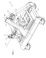
- FIG. 3 is an expanded/exploded view of the gripper shown in FIG. 1.
- the friction welder 20 is an apparatus for friction welding a first element 21 to a second element 22 .
- An indexing turret (not shown) which in operation would hold the second element 22 in the illustrated position has been removed for clarity.
- the first element 21 is a rotor blade, or airfoil and the second element 22 is a rotor disk. Once all the rotor blades are welded to the rotor disk an integrally bladed rotor is formed.
- the friction welder 20 generally includes a frame 23 , a forge assembly 24 , and a reciprocal motion assembly 26 .
- the frame 23 includes a plurality of trusses, represented by the diagonal truss 32 , which form a pyramid-like configuration.
- the forge assembly 24 is supported by the frame 23 and provides a forge load along a forge axis F a .
- the reciprocal motion assembly 26 is supported by the frame 23 , and is adapted to generate reciprocating motion between the first and second elements (blades and disks) 21 and 22 , respectively.
- the reciprocal motion assembly 26 includes an hydraulic actuator assembly 90 and a slide 94 .
- the slide 94 is slidingly engaged with the diagonal truss 32 of the frame 23 .
- the slide By means of the hydraulic actuator assembly 90 the slide is made to move along the motion axis M a in a linear reciprocating motion.
- the motion axis M a is perpendicular to the forge axis F a .
- a gripper 102 is attached to the slide 94 , and holds the first element 21 , so that when the slide 94 is moved, the first element 21 also moves relative to the second element 22 .
- the first element 21 which is characterized by an airfoil shaped portion disposed within a collar 204 .
- the collar 204 should be shaped to allow no interference with other airfoils 21 which are subsequently bonded to disk 22 .
- the gripper 102 includes a U-shaped base 206 , a first clamp half 208 , a second clamp half 210 , a pair of straps 212 , and a pair of fasteners 214 .
- the U-shaped base 206 is engageable with the reciprocal motion assembly 26 (as shown in Fig. 1).
- the base 206 includes two spaced end walls 216 and 217 with a center wall 218 having attachment points 220 thereon.
- End wall 216 includes an inclined inner surface 222 and end wall 217 includes an upright (non-inclined) inner surface 223 .
- Each end wall has a cutout 224 having inclined side walls in the free end thereof. The inner surfaces are spaced apart to accommodate the clamp halves 208 and 210 therebetween.
- bores represented by the bore 226 (FIG. 3).
- the gripper of the present invention is attached directly to the slide at attachment points 220 by a plurality of threaded bolts which extend through the center wall 218 of the base at points 220 . Although threaded bolts are used, the present invention is not limited thereto.
- the clamp halves 208 and 210 are substantially T-shaped. Each clamp half is characterized by an upper surface 228 with a shoulder 230 . A cross bar 232 of each clamp half is provided with a bore 234 therethrough, and includes a flange 236 . A vertically extending foot 238 of each clamp half is characterized by a pair of opposed outer surfaces 240 .
- the gripper 102 With the base 206 attached to the slide 94 , and the friction welder 20 in an unloaded position, where the disk 22 is spaced from the base 206 , the blade 21 is inserted in the gripper 102 . Referring to FIGS. 2 and 3, the two clamp halves 208 and 210 are joined about the blade 21 , so that the shoulders 230 fit snugly about the collar 40 . Then the clamp halves 208 and 210 , thus joined, are installed in the base 206 , such that the ends of the cross bars 232 of the clamp halves 208 and 210 engage the cutouts 224 in the end walls 216 of the base 206 .
- each of the clamp halves 208 and 210 are aligned with the respective bores 226 in the base 206 .
- inner angled surfaces 222 of the base 206 mate with the outer surfaces 240 of the clamp halves 208 and 210 .
- the pair of straps 212 are fit over the combined clamp halves 208 and 210 .
- Bolts 214 are inserted through the straps and extend into the threaded bores 226 in the base.
- the bolts 214 are tightened the clamp halves 208 and 210 are pulled into the base 206 until the cross bars 232 of the clamp halves bottom out in the cutouts 224 in the base 206 .
- the engagement of the inclined end walls of the clamp valves with the inclined wall 222 of the base cams the clamp halves into a tight, clamping engagement with the blade collar in both longitudinal and lateral directions.
- the straps are optional. The straps are used to force both clamp halves into the cutout.
- the friction welding process may start with the application of an initial forge load by the forge assembly 24 , and then activation of the reciprocal motion assembly 26 , or the reciprocal motion may be initiated prior to application of any forge load. Either way, the desired forge load and oscillating frequencies may be applied via the forge assembly 24 and the reciprocating motion assembly 26 .
- the forge load is directed along the forge axis F a normal to the motion axis M a . It is preferred that the forge load be applied then released initially in order to force the clamp halves 208 and 210 further into the cutouts, prior to the tightening of fasteners 214 .
- the forge load is then applied in order to start bonding.
- the forge load is applied by moving the disk 22 into contact with the blade 21 , which is the loaded position. Oscillation of the blade 21 is achieved by activation of the hydraulic actuator assembly 90. This causes the slide 94 , gripper 102 , and the blade 21 to reciprocate along the motion axis M a . During oscillation of the blade 21 , the disk 22 is held stationary. As a result of the forge load clamp halves 208 and 210 are further urged into the base 206 . Thus, the gripping force on the blade 21 and clamp halves due to the clamping of straps 212 is augmented by the forge load.
- the application of the forge load and reciprocating load causes the bonding surfaces of the elements 21 and 22 to heat up due to friction, which plasticizes the metal components, which are then diffusion bonded by the forge loading.
- bolts 214 are removed from the gripper 102 .
- the forge assembly 26 is then actuated, causing the disk 22 to move away from the diagonal truss 31 , pulling the blade 21 now bonded to the second element 22 , out of the gripper 102 .
- Subsequent blades are bonded to the disk in the aforementioned manner. Once the entire intergrally bladed rotor is formed the collars 204 are machined off the blades.
- the principle advantage to the present invention is that the gripper clamps the first element sufficiently to withstand the forces exerted by the friction welder, and holds the blade so that the final position of the blade is accurate and repeatable.
- the gripper supports the first element in such a way as to minimize the likelihood of the first element breaking and without altering its shape or introducing stress- into it.
- Yet another advantage of the gripper is that it allows blades which are close together to be bonded since the gripper will not interfere with neighboring blades. Furthermore the gripper is easy to disengage from the bonded blade.
Landscapes
- Engineering & Computer Science (AREA)
- Mechanical Engineering (AREA)
- Pressure Welding/Diffusion-Bonding (AREA)
Applications Claiming Priority (2)
| Application Number | Priority Date | Filing Date | Title |
|---|---|---|---|
| US09/187,511 US6244495B1 (en) | 1998-11-06 | 1998-11-06 | Gripper |
| US187511 | 1998-11-06 |
Publications (3)
| Publication Number | Publication Date |
|---|---|
| EP1000697A2 true EP1000697A2 (fr) | 2000-05-17 |
| EP1000697A3 EP1000697A3 (fr) | 2002-04-24 |
| EP1000697B1 EP1000697B1 (fr) | 2005-05-25 |
Family
ID=22689291
Family Applications (1)
| Application Number | Title | Priority Date | Filing Date |
|---|---|---|---|
| EP99308882A Expired - Lifetime EP1000697B1 (fr) | 1998-11-06 | 1999-11-08 | Pince |
Country Status (4)
| Country | Link |
|---|---|
| US (1) | US6244495B1 (fr) |
| EP (1) | EP1000697B1 (fr) |
| JP (1) | JP2000141063A (fr) |
| DE (1) | DE69925438T2 (fr) |
Cited By (2)
| Publication number | Priority date | Publication date | Assignee | Title |
|---|---|---|---|---|
| EP1213088A1 (fr) * | 2000-12-07 | 2002-06-12 | Snecma Moteurs | Outillage de maintien d'une aube, et son application au soudage par friction des aubes |
| WO2021047999A1 (fr) * | 2019-09-10 | 2021-03-18 | Safran Aero Boosters | Outillage de maintien d'une aube pendant son soudage par friction a un element rotorique d'une turbomachine d'aeronef |
Families Citing this family (12)
| Publication number | Priority date | Publication date | Assignee | Title |
|---|---|---|---|---|
| US7225967B2 (en) * | 2003-12-16 | 2007-06-05 | The Boeing Company | Structural assemblies and preforms therefor formed by linear friction welding |
| US7398911B2 (en) * | 2003-12-16 | 2008-07-15 | The Boeing Company | Structural assemblies and preforms therefor formed by friction welding |
| EP1801432A3 (fr) * | 2005-12-20 | 2009-07-22 | Yamaha Hatsudoki Kabushiki Kaisha | Bielle et son procédé de fabrication |
| US8613138B2 (en) | 2009-12-16 | 2013-12-24 | United Technologies Corporation | Repair of integrally bladed rotors |
| GB2514086B (en) * | 2013-03-11 | 2017-12-06 | Kuka Systems Uk Ltd | Linear friction welding |
| JP6156022B2 (ja) * | 2013-09-30 | 2017-07-05 | 株式会社Ihi | 一体型翼車の線形摩擦接合装置用治具ユニット |
| JP6255956B2 (ja) * | 2013-12-05 | 2018-01-10 | 株式会社Ihi | 一体型翼車の線形摩擦接合装置用治具ユニット |
| CN104439834A (zh) * | 2014-11-19 | 2015-03-25 | 芜湖普威技研有限公司 | 一种汽车油门拉线头焊接夹具 |
| JP6984418B2 (ja) * | 2018-01-04 | 2021-12-22 | 株式会社Ihi | ブリスクの製作方法及び装置 |
| JP7003666B2 (ja) * | 2018-01-04 | 2022-01-20 | 株式会社Ihi | ブリスクの製作方法及び保持治具 |
| WO2020170765A1 (fr) * | 2019-02-22 | 2020-08-27 | 国立大学法人大阪大学 | Gabarit de fixation pour soudage par friction linéaire et procédé de soudage par friction linéaire |
| CN112756889B (zh) * | 2021-01-17 | 2022-11-29 | 西北工业大学 | 一种线性摩擦焊接夹具 |
Citations (5)
| Publication number | Priority date | Publication date | Assignee | Title |
|---|---|---|---|---|
| US2864087A (en) * | 1954-08-31 | 1958-12-16 | Danly Mach Specialties Inc | Punching and assembling device |
| EP0458630A1 (fr) * | 1990-05-24 | 1991-11-27 | ROLLS-ROYCE plc | Soudage à friction |
| EP0624418A2 (fr) * | 1993-05-13 | 1994-11-17 | ROLLS-ROYCE plc | Soudage par friction |
| US5551623A (en) * | 1994-02-23 | 1996-09-03 | Societe Nationale D'etude Et De Construction De Moteurs D'aviation "Snecma" | Process for welding two blade parts |
| EP0841470A2 (fr) * | 1996-11-12 | 1998-05-13 | United Technologies Corporation | Méthode de connexion d'une aube à un rotor intégral |
Family Cites Families (32)
| Publication number | Priority date | Publication date | Assignee | Title |
|---|---|---|---|---|
| JPS5341107B1 (fr) | 1968-02-10 | 1978-10-31 | ||
| US3711009A (en) | 1968-02-13 | 1973-01-16 | Toyoda Automatic Loom Works | Apparatus for optionally selecting the thrust force in friction welding |
| US3567100A (en) | 1968-05-13 | 1971-03-02 | Caterpillar Tractor Co | Friction-welding apparatus and method |
| US3720993A (en) | 1968-05-13 | 1973-03-20 | Caterpillar Tractor Co | Friction welding method |
| GB1293531A (en) | 1968-07-20 | 1972-10-18 | John Thompson Pipe Work And Or | Improvements relating to methods of and apparatus for friction welding |
| GB1293532A (en) | 1968-07-20 | 1972-10-18 | John Thompson Pipe Work And Or | Improvements relating to methods of and apparatus for friction welding |
| GB1385471A (en) | 1971-02-10 | 1975-02-26 | Allwood Searle Timney Ltd | Friction welding apparatus |
| US3771706A (en) | 1971-09-07 | 1973-11-13 | Us Army | Apparatus for welding by translational friction |
| US3840168A (en) | 1971-10-27 | 1974-10-08 | Allwood Searle & Timney | Friction welding apparatus |
| US4086122A (en) | 1976-12-17 | 1978-04-25 | Hydroacoustics Inc. | Hydroacoustic welder |
| US4377428A (en) | 1981-06-15 | 1983-03-22 | Branson Ultrasonics Corporation | Method of friction welding |
| GB8601083D0 (en) | 1986-01-17 | 1986-02-19 | Welding Inst | Friction welding |
| JPH02501545A (ja) | 1986-12-09 | 1990-05-31 | ロールス―ロイス・ピーエルシー | 摩擦溶接装置 |
| US4844320A (en) | 1987-02-17 | 1989-07-04 | General Electric Company | Control system and method for vibration welding |
| GB8709286D0 (en) | 1987-04-16 | 1987-05-20 | Rolls Royce Plc | Oscillating mechanism |
| GB2207878B (en) | 1987-08-01 | 1991-10-16 | Rolls Royce Plc | Friction welder mechanism |
| US4864706A (en) | 1987-08-12 | 1989-09-12 | United Technologies Corporation | Fabrication of dual alloy integrally bladed rotors |
| GB8822235D0 (en) | 1988-09-21 | 1988-10-26 | Allwood Searle & Timney | Friction welding |
| US4873751A (en) | 1988-12-27 | 1989-10-17 | United Technologies Corporation | Fabrication or repair technique for integrally bladed rotor assembly |
| GB8910452D0 (en) | 1989-05-06 | 1989-06-21 | Allwood Searle & Timney | Friction welding |
| GB8914273D0 (en) | 1989-06-21 | 1989-08-09 | Rolls Royce Plc | Friction bonding apparatus |
| US5188275A (en) | 1990-05-24 | 1993-02-23 | Rolls-Royce Plc | Friction bonding clamp for a rotor blade |
| US5113583A (en) | 1990-09-14 | 1992-05-19 | United Technologies Corporation | Integrally bladed rotor fabrication |
| US5160393A (en) | 1990-12-27 | 1992-11-03 | Hydroacoustics, Inc. | Friction welder having an electromagnetic drive which produces orbital motion |
| US5197190A (en) | 1991-03-04 | 1993-03-30 | United Technologies Corporation | Fabrication of repair method for an integrally bladed rotor |
| US5109606A (en) | 1991-03-04 | 1992-05-05 | United Technologies Corporation | Integrally bladed rotor fabrication or repair |
| DE4238281C2 (de) | 1992-11-13 | 1994-09-08 | Sauter Kg Feinmechanik | Werkzeugrevolver |
| GB9309864D0 (en) | 1993-05-13 | 1993-06-23 | Allwood Searle & Timney | Improvements relating to friction welding |
| GB9309819D0 (en) | 1993-05-13 | 1993-06-23 | Allwood Searle & Timney | Imprivements relating to friction welding |
| GB2279597B (en) | 1993-05-13 | 1996-05-15 | Rolls Royce Plc | Improvements relating to friction welding |
| GB2296885B (en) | 1994-12-23 | 1998-02-04 | Rolls Royce Plc | Friction welding tooling |
| US5813593A (en) * | 1996-11-15 | 1998-09-29 | General Electric Company | Translational friction welding apparatus and method |
-
1998
- 1998-11-06 US US09/187,511 patent/US6244495B1/en not_active Expired - Fee Related
-
1999
- 1999-11-08 EP EP99308882A patent/EP1000697B1/fr not_active Expired - Lifetime
- 1999-11-08 JP JP11316521A patent/JP2000141063A/ja not_active Ceased
- 1999-11-08 DE DE69925438T patent/DE69925438T2/de not_active Expired - Lifetime
Patent Citations (5)
| Publication number | Priority date | Publication date | Assignee | Title |
|---|---|---|---|---|
| US2864087A (en) * | 1954-08-31 | 1958-12-16 | Danly Mach Specialties Inc | Punching and assembling device |
| EP0458630A1 (fr) * | 1990-05-24 | 1991-11-27 | ROLLS-ROYCE plc | Soudage à friction |
| EP0624418A2 (fr) * | 1993-05-13 | 1994-11-17 | ROLLS-ROYCE plc | Soudage par friction |
| US5551623A (en) * | 1994-02-23 | 1996-09-03 | Societe Nationale D'etude Et De Construction De Moteurs D'aviation "Snecma" | Process for welding two blade parts |
| EP0841470A2 (fr) * | 1996-11-12 | 1998-05-13 | United Technologies Corporation | Méthode de connexion d'une aube à un rotor intégral |
Cited By (6)
| Publication number | Priority date | Publication date | Assignee | Title |
|---|---|---|---|---|
| EP1213088A1 (fr) * | 2000-12-07 | 2002-06-12 | Snecma Moteurs | Outillage de maintien d'une aube, et son application au soudage par friction des aubes |
| FR2817783A1 (fr) * | 2000-12-07 | 2002-06-14 | Snecma Moteurs | Outillage de maintien d'une aube, et son application au soudage par friction des aubes |
| US6595401B2 (en) | 2000-12-07 | 2003-07-22 | Snecma-Moteurs | Blade maintenance tool, and its application to friction welding of blades |
| WO2021047999A1 (fr) * | 2019-09-10 | 2021-03-18 | Safran Aero Boosters | Outillage de maintien d'une aube pendant son soudage par friction a un element rotorique d'une turbomachine d'aeronef |
| BE1027565B1 (fr) * | 2019-09-10 | 2021-04-06 | Safran Aero Boosters Sa | Outillage de maintien d’une aube pendant son soudage par friction à un élément rotorique d’une turbomachine d’aéronef |
| US11858061B2 (en) | 2019-09-10 | 2024-01-02 | Safran Aero Boosters | Tooling for retaining a blade during friction welding thereof to a rotor element of an aircraft turbomachine |
Also Published As
| Publication number | Publication date |
|---|---|
| EP1000697B1 (fr) | 2005-05-25 |
| JP2000141063A (ja) | 2000-05-23 |
| EP1000697A3 (fr) | 2002-04-24 |
| US6244495B1 (en) | 2001-06-12 |
| DE69925438D1 (de) | 2005-06-30 |
| DE69925438T2 (de) | 2005-11-17 |
Similar Documents
| Publication | Publication Date | Title |
|---|---|---|
| US6244495B1 (en) | Gripper | |
| US5035411A (en) | Friction bonding apparatus | |
| US6779708B2 (en) | Joining structural members by friction welding | |
| EP0624418B1 (fr) | Soudage par friction | |
| US4516296A (en) | Tubing clamp and method of making the same | |
| US5813593A (en) | Translational friction welding apparatus and method | |
| CA3042636C (fr) | Appareil et procede de soudage a friction lineaire | |
| EP1000696B1 (fr) | Appareil pour le soudage par friction | |
| US20120224972A1 (en) | Method and device for producing an integrally bladed rotor and rotor produced by means of the method | |
| US5153996A (en) | Rivet connector for hedge cutting blade | |
| JP4580762B2 (ja) | 2個以上の構成部材を互いに結合させる方法 | |
| JP2018083283A (ja) | 積層造形法のための支持体除去工具 | |
| AU2006230660B2 (en) | Stranded bar to solidified bar braze method and series loop connection | |
| EP1000695A2 (fr) | Tourelle d'indexation | |
| WO2019074612A1 (fr) | Tête de soudage par friction à pince de serrage en deux parties | |
| KR200185691Y1 (ko) | 표면처리 공정용 지그장치 | |
| KR100971072B1 (ko) | 베어링 캡 강제분리방법 및 그 장치 | |
| CN214641865U (zh) | 金属棒枷具 | |
| JP4405087B2 (ja) | 部分配管の接続装置 | |
| WO1995020441A1 (fr) | Fabrication de lame creuse en titane | |
| JP2746072B2 (ja) | 鉄筋の突合せ溶接方法 | |
| SU1140929A1 (ru) | Устройство дл двухсторонней сборки запрессовкой обхватываемой и обхватывающих деталей | |
| WO2013085967A1 (fr) | Appareil et procédé pour réparations par soudage par friction linéaire | |
| US6894244B2 (en) | Method for fabricating embossed articles by flash welding | |
| WO1995014325A1 (fr) | Procede de fabrication d'un stator pour une machine electrique rotative |
Legal Events
| Date | Code | Title | Description |
|---|---|---|---|
| PUAI | Public reference made under article 153(3) epc to a published international application that has entered the european phase |
Free format text: ORIGINAL CODE: 0009012 |
|
| AK | Designated contracting states |
Kind code of ref document: A2 Designated state(s): AT BE CH CY DE DK ES FI FR GB GR IE IT LI LU MC NL PT SE Kind code of ref document: A2 Designated state(s): DE FR GB |
|
| AX | Request for extension of the european patent |
Free format text: AL;LT;LV;MK;RO;SI |
|
| PUAL | Search report despatched |
Free format text: ORIGINAL CODE: 0009013 |
|
| AK | Designated contracting states |
Kind code of ref document: A3 Designated state(s): AT BE CH CY DE DK ES FI FR GB GR IE IT LI LU MC NL PT SE |
|
| AX | Request for extension of the european patent |
Free format text: AL;LT;LV;MK;RO;SI |
|
| RIC1 | Information provided on ipc code assigned before grant |
Free format text: 7B 23K 20/12 A, 7B 23P 15/00 B |
|
| 17P | Request for examination filed |
Effective date: 20020905 |
|
| 17Q | First examination report despatched |
Effective date: 20021025 |
|
| AKX | Designation fees paid |
Free format text: DE FR GB |
|
| GRAP | Despatch of communication of intention to grant a patent |
Free format text: ORIGINAL CODE: EPIDOSNIGR1 |
|
| GRAS | Grant fee paid |
Free format text: ORIGINAL CODE: EPIDOSNIGR3 |
|
| GRAA | (expected) grant |
Free format text: ORIGINAL CODE: 0009210 |
|
| AK | Designated contracting states |
Kind code of ref document: B1 Designated state(s): DE FR GB |
|
| REG | Reference to a national code |
Ref country code: GB Ref legal event code: FG4D |
|
| REG | Reference to a national code |
Ref country code: IE Ref legal event code: FG4D |
|
| REF | Corresponds to: |
Ref document number: 69925438 Country of ref document: DE Date of ref document: 20050630 Kind code of ref document: P |
|
| ET | Fr: translation filed | ||
| PLBE | No opposition filed within time limit |
Free format text: ORIGINAL CODE: 0009261 |
|
| STAA | Information on the status of an ep patent application or granted ep patent |
Free format text: STATUS: NO OPPOSITION FILED WITHIN TIME LIMIT |
|
| 26N | No opposition filed |
Effective date: 20060228 |
|
| PGFP | Annual fee paid to national office [announced via postgrant information from national office to epo] |
Ref country code: FR Payment date: 20081106 Year of fee payment: 10 |
|
| REG | Reference to a national code |
Ref country code: FR Ref legal event code: ST Effective date: 20100730 |
|
| PG25 | Lapsed in a contracting state [announced via postgrant information from national office to epo] |
Ref country code: FR Free format text: LAPSE BECAUSE OF NON-PAYMENT OF DUE FEES Effective date: 20091130 |
|
| PGFP | Annual fee paid to national office [announced via postgrant information from national office to epo] |
Ref country code: DE Payment date: 20121031 Year of fee payment: 14 |
|
| PGFP | Annual fee paid to national office [announced via postgrant information from national office to epo] |
Ref country code: GB Payment date: 20121107 Year of fee payment: 14 |
|
| GBPC | Gb: european patent ceased through non-payment of renewal fee |
Effective date: 20131108 |
|
| REG | Reference to a national code |
Ref country code: DE Ref legal event code: R119 Ref document number: 69925438 Country of ref document: DE Effective date: 20140603 |
|
| PG25 | Lapsed in a contracting state [announced via postgrant information from national office to epo] |
Ref country code: DE Free format text: LAPSE BECAUSE OF NON-PAYMENT OF DUE FEES Effective date: 20140603 |
|
| PG25 | Lapsed in a contracting state [announced via postgrant information from national office to epo] |
Ref country code: GB Free format text: LAPSE BECAUSE OF NON-PAYMENT OF DUE FEES Effective date: 20131108 |