EP1000632B1 - Closure element - Google Patents
Closure element Download PDFInfo
- Publication number
- EP1000632B1 EP1000632B1 EP99120405A EP99120405A EP1000632B1 EP 1000632 B1 EP1000632 B1 EP 1000632B1 EP 99120405 A EP99120405 A EP 99120405A EP 99120405 A EP99120405 A EP 99120405A EP 1000632 B1 EP1000632 B1 EP 1000632B1
- Authority
- EP
- European Patent Office
- Prior art keywords
- closure element
- medical article
- article according
- wall
- incision
- Prior art date
- Legal status (The legal status is an assumption and is not a legal conclusion. Google has not performed a legal analysis and makes no representation as to the accuracy of the status listed.)
- Expired - Lifetime
Links
Images


Classifications
-
- A—HUMAN NECESSITIES
- A61—MEDICAL OR VETERINARY SCIENCE; HYGIENE
- A61M—DEVICES FOR INTRODUCING MEDIA INTO, OR ONTO, THE BODY; DEVICES FOR TRANSDUCING BODY MEDIA OR FOR TAKING MEDIA FROM THE BODY; DEVICES FOR PRODUCING OR ENDING SLEEP OR STUPOR
- A61M39/00—Tubes, tube connectors, tube couplings, valves, access sites or the like, specially adapted for medical use
- A61M39/20—Closure caps or plugs for connectors or open ends of tubes
-
- A—HUMAN NECESSITIES
- A61—MEDICAL OR VETERINARY SCIENCE; HYGIENE
- A61M—DEVICES FOR INTRODUCING MEDIA INTO, OR ONTO, THE BODY; DEVICES FOR TRANSDUCING BODY MEDIA OR FOR TAKING MEDIA FROM THE BODY; DEVICES FOR PRODUCING OR ENDING SLEEP OR STUPOR
- A61M1/00—Suction or pumping devices for medical purposes; Devices for carrying-off, for treatment of, or for carrying-over, body-liquids; Drainage systems
- A61M1/14—Dialysis systems; Artificial kidneys; Blood oxygenators ; Reciprocating systems for treatment of body fluids, e.g. single needle systems for hemofiltration or pheresis
- A61M1/16—Dialysis systems; Artificial kidneys; Blood oxygenators ; Reciprocating systems for treatment of body fluids, e.g. single needle systems for hemofiltration or pheresis with membranes
- A61M1/168—Sterilisation or cleaning before or after use
- A61M1/169—Sterilisation or cleaning before or after use using chemical substances
-
- B—PERFORMING OPERATIONS; TRANSPORTING
- B01—PHYSICAL OR CHEMICAL PROCESSES OR APPARATUS IN GENERAL
- B01D—SEPARATION
- B01D61/00—Processes of separation using semi-permeable membranes, e.g. dialysis, osmosis or ultrafiltration; Apparatus, accessories or auxiliary operations specially adapted therefor
- B01D61/24—Dialysis ; Membrane extraction
- B01D61/30—Accessories; Auxiliary operation
-
- B—PERFORMING OPERATIONS; TRANSPORTING
- B01—PHYSICAL OR CHEMICAL PROCESSES OR APPARATUS IN GENERAL
- B01D—SEPARATION
- B01D65/00—Accessories or auxiliary operations, in general, for separation processes or apparatus using semi-permeable membranes
-
- B—PERFORMING OPERATIONS; TRANSPORTING
- B01—PHYSICAL OR CHEMICAL PROCESSES OR APPARATUS IN GENERAL
- B01D—SEPARATION
- B01D65/00—Accessories or auxiliary operations, in general, for separation processes or apparatus using semi-permeable membranes
- B01D65/02—Membrane cleaning or sterilisation ; Membrane regeneration
- B01D65/022—Membrane sterilisation
Definitions
- the present invention relates to a medical article consisting from a filter module for dialysis, Hemo- or ultrafiltration.
- filter modules In the manufacture of such filter modules, there is a need for these to sterilize the actual manufacturing process and also against external influences, such as. the penetration of germs or dirt particles.
- One Method for the sterilization of filter modules is the so-called inline sterilization, during which the inner areas of the filter module are cleaned while sterilization on the outside does not take place. Because every open contact of the connections the filter module during or after the sterilization step must be avoided, the filter module must be sealed in such a way that neither during sterilization nor after the removal of the sterilization device Contamination or contamination of the interior of the filter module can be done.
- a Wall includes an automatically closing slot-shaped incision which is germ-tight in the closed state, and that fastening means are provided, which adjoin the wall and by means of which the Closure element with a connection is sealingly connectable.
- a closure element is simple and causes due to the self-closing slit-shaped incision provides a reliable and sterile seal of a medical Article consisting of one Filter module, during and after sterilization.
- connection element after the successful sterilization or treatment removed the closure element according to the invention, closes the slot-shaped Incision automatically and thus prevents contamination of the sterilized area and additionally the leakage of the closure element according to the invention closed article.
- the closure element is a substantially cylindrical Shape, wherein the fastening means through the cylindrical surface are formed and the slot-shaped incision in one of the end faces of the cylinder is arranged.
- the closure element is germ-proof associated with a connection of the medical article.
- Cap-like design of the closure element has the advantage that the supplied or discharged liquid when passing through the closure element a traverses simple, straight-line path, whereby with appropriate arrangement of the Slit-shaped incision the formation of dead zones are effectively avoided can.
- This has the advantage that a mixture of different Liquids, e.g. containing different drugs or medications Mixtures, avoided by different residence times in the closure element can be.
- the closure element is executed symmetrically.
- Such a structure does not simplify only the production of the closure element, but also allows a simple handling or a simple installation and insertion of the closure element on the appropriate connection, for example, a filter module.
- the slit-shaped incision is cross-shaped or star-shaped.
- It may be one of the incision having wall opposite other Be provided wall having an opening for the passage of a fluid. In this case, the central region of the incision and the opening with each other aligned.
- closure element according to the invention is in one piece is executed. This results in corresponding advantages in the manufacturing process.
- the entire closure element made of plastic.
- This results in the one advantage is that by choosing a suitable plastic flexibility and elasticity of the closure element can be varied within wide ranges. About that In addition, the compatibility with the used by the choice of the plastic Liquid or with a mixture containing different active ingredients to reach.
- the use of plastic for the incision Wall of the closure element or for the entire closure element also has the advantage that due to the simple and inexpensive manufacturing process a variety of different embodiments and configurations the closure element can be produced. It is particularly advantageous if the plastic is silicone.
- the spring element from alternating or single on the top and / or bottom of the Wall arranged recesses is formed.
- the depressions may be part-circular be executed.
- the slit-shaped incision of the closure element up to a pressure difference of +/- 0.25 bar germ-proof closes.
- the present invention further relates to the use of an inventive Closure element for the sterile closure of connections of medical articles, wherein the closure element for inline sterilization of the filter module is used.
- the fastening means the closure element is designed such that the closure element can be used on or in protruding or bush-shaped connections is.
- closure element is designed such that the inner surface of the closure element with the outer surface of a protruding Connection or the outer surface of the closure element with the inner surface a socket-shaped connection are connected germ-tight.
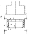
- Fig. 1 shows the closure element 10 according to the invention with the parallel Walls 12 and 14. Both walls 12, 14 limit the cylindrical Cavity 20, which further by the adjoining the walls 12, 14 and is set as a fastener serving cylindrical surfaces. The Walls 12 and 14 are perpendicular to the cylindrical surfaces of the closure element 10 on.
- the wall 14 has the slot-shaped and automatically closing incision 141 with the central portion 143 on.
- the opening 121 which is circular in the present embodiment is.
- the opening 121 and the central portion 143 of the incision 141 the wall 14 are aligned with each other, so that the present closure element can be used for the use of straight-line Konnetations instituten.
- Fig. 1 right shows a housing opening, for example a filter module, for Recording of the closure element 10 according to the invention.
- This is advantageous also made cylindrical and takes before the start of operation, the closure element 10 positively on.
- the outer diameter of the closure element 10 slightly above the inside diameter of the housing recess. This will also provide a safe and germ-proof seal between the housing and closure element 10 is generated.
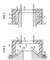
- Fig. 2 shows a view of the closure element 10 of the invention from the Perspective A-A (left) and B-B (right) of FIG. 1.
- the solid lines in Fig. 2 correspond to the visible contours of the closure element 10, while the broken lines represent cut edges in the chosen perspective are not visible.
- Fig. 2, left shows the closure element 10 with the Wall 14, which the self-closing slot-shaped incision 141 with a central portion 143.
- the cylindrical surfaces of the hollow cylinder are in Fig. 2 by the outermost solid and the inwardly offset perforated Line shown.
- Fig. 2, right shows the wall 14 opposite Wall 12. In this is the circular and centric opening 121st
- Fig. 2 illustrates that the opening 121 and the central portion 143 of slit-shaped incision 141 aligned with each other.
- the slit-shaped incision 141 is shown in Fig. 2, right as a partially broken line, since this in the selected view is visible only within the opening 121.
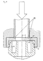
- Fig. 3 shows the closure element 10 according to the invention during a sterilization process.
- the introduced according to FIG. 3 from the left neck of the sterilization device is introduced so that it first touches the wall 14 and the further insertion the elastically designed wall 14 deformed such that the slit-shaped incision 141 closed in the unused state expands and forms an opening for the inflowing or outflowing sterilizing medium, which may be formed as a liquid, gas or vapor.
- Embodiment is a seal by means of a sterilizer located sealing ring 30, which receives over the closure element 10 Housing seals.
- the sterilization liquid now passes through the opening 141 in the cavity 20 of the closure element 10 and in the ring area, which extends up to the voltage applied to the housing sealing ring 30.
- the Liquid After passing of the slot-shaped incision 141 deformed to an opening, the Liquid through the opening 121 in the component to be sterilized, for example in a dialysis filter.
- the wall 14 of the closure element 10 After removal of the Sterilisations réelleestutzens at termination the process, the wall 14 of the closure element 10 is in its original Shape deformed, whereby the opening closes and again a slot-shaped incision 141 forms.
- Fig. 4 the closure element 10 according to the invention during the intended Use shown.
- This is a Konneticiansstutzen so inserted through the slot-shaped incision 141 of the wall 14 until the end face the Konnezzysstutzens to the cavity 20 of the closure element 10 adjacent side of the wall 12 sealingly abuts.
- the Diameter of the connection socket are doing on both sides of the slit-shaped incision 141 located areas of the wall 14 in the direction the wall 12 is curved, as shown in FIG. 4 can be seen.
- the added or to be discharged Liquid now passes through the opening of the connection socket and through the opening 121 of the wall 12 in or out of the connected component, for example a connected dialysis filter.
- FIG. 4 illustrates that at a correspondingly favorable vote of Konnetechnischsstutzen and closure element a rectilinear passage for the liquid is achieved, thereby the formation of undesirable dead zones are largely avoided can.
- Figs. 5-7 show a second embodiment of the closure element according to the invention 10th
- Fig. 5 is a plan view of the second embodiment of the closure element 10 is shown.
- the closure element 10 has a cylindrical shape, wherein in the apparent in Fig. 5 end face of the self-closing slot-shaped Incision 141 of the wall 14 can be seen.
- the spring elements 145 arranged in the right and left of the slot-shaped incision 141 extending areas. These serve the radial tension forces in the transverse direction in the spring element profile by a cross-sectional reduction of the wall 14 lower.
- Fig. 5 illustrates that the spring elements 145 are not complete, but partially circular extend around the slit-shaped incision 141 of the wall 14 and in the region 149 extending in the longitudinal direction of the incision 141 not are provided. This results in the advantage that the radial force effect in Closing direction is increased, resulting in a particularly effective and germ-tight Closure of the incision 141 results. Such a structural design the closure element with spring elements 145 thus leads to that an improved sealing behavior of the incision 141 of the wall 14 results.
- the spring portions 145 can be advantageously carried out such that when executed the closure element 10 made of silicone according to the present Embodiment in the unloaded state, a pressure difference of +/- 0.25 bar is tolerable without the incision 141 loses its sealing effect.
- FIG. 6 From the longitudinal sectional view of FIG. 6 also shows that the from the wall 14 extending vertically and serving as a fastener Cylinder shell in its end region has the circumferential projection 131. This serves to the closure element 10 in a corresponding recess to lock the port shown in Fig. 7 42 and safe there to fix.
- Fig. 7 shows a longitudinal section of the inserted closure element 10 in the Embodiment according to FIGS. 5 and 6.
- the closure element 10 is here on the projecting connecting piece 42 and placed by means of the circumferential projection 131 arrested.
- the incision 141 is slightly or fully opened.
- closure element 10th is designed such that its cylindrical surface forming the fastener both is executed on the outside and on the inside to fit. from that shows that the patch or inserted closure element 10 via the inner surface with the outer surface of a protruding connecting piece 42 and over the outer surface with the inner surface of a sleeve-shaped connecting piece ensures a germ-tight closure.
Description
Die vorliegende Erfindung betrifft einem medizinischen Artikel bestehend aus einem Filtermodul für die Dialyse, Hämo- oder Ultrafiltration.The present invention relates to a medical article consisting from a filter module for dialysis, Hemo- or ultrafiltration.
Bei der Herstellung derartiger Filtermodule besteht die Notwendigkeit, diese nach dem eigentlichen Herstellprozeß zu sterilisieren und ferner vor äußeren Einflüssen, wie z.B. dem Eindringen von Keimen oder Schmutzpartikeln, zu schützen. Ein Verfahren zur Sterilisation von Filtermodulen ist die sogenannte Inline-Sterilisation, bei der die innenliegenden Bereiche des Filtermoduls gereinigt werden, während eine Sterilisation an der Außenseite nicht erfolgt. Da jeder offene Kontakt der Anschlüsse des Filtermoduls bei oder nach der Durchführung des Sterilisationsschrittes zwingend zu vermeiden ist, muß das Filtermodul derart abgedichtet werden, daß weder während der Sterilisation noch nach der Abnahme von der Sterilisationsvorrichtung eine Kontamination oder Verschmutzung des Innenraums des Filtermoduls erfolgen kann.In the manufacture of such filter modules, there is a need for these to sterilize the actual manufacturing process and also against external influences, such as. the penetration of germs or dirt particles. One Method for the sterilization of filter modules is the so-called inline sterilization, during which the inner areas of the filter module are cleaned while sterilization on the outside does not take place. Because every open contact of the connections the filter module during or after the sterilization step must be avoided, the filter module must be sealed in such a way that neither during sterilization nor after the removal of the sterilization device Contamination or contamination of the interior of the filter module can be done.
Aus der EP 0 352 540 ist ein gattungsgemäßer Artikel mit einem Verschlußelement bekannt, das aus zwei Teilen besteht, von denen das erste Verschlußelementteil an dem Anschluß des Filtermoduls bzw. Dialysators angebracht wird, während das zweite Verschlußelementteil in einem Aufnahmeraum des ersten Verschlußelementteils aufgenommen ist. Es ist in diesem Aufnahmeraum zwischen einer Offenstellung und einer Schließstellung bewegbar angeordnet. Somit läßt sich in der Offenstellung ein Durchtritt des Sterilisationsmediums bzw. die Sterilisation sämtlicher Dichtund Führungsflächen erreichen und in der Schließstellung die zuverlässige Abdichtung des Dialysators erzielen. Ein derartiges Verschlußelement gewährleistet zwar die zuverlässige Abdichtung des Filtermoduls, weist jedoch den Nachteil eines verhältnismäßig komplexen Aufbaus auf.From EP 0 352 540 a generic article with a closure element is known, the consists of two parts, of which the first closure element part at the terminal the filter module or dialyzer is attached, while the second Closure element part in a receiving space of the first closure element part is included. It is in this recording room between an open position and a closed position movably arranged. Thus can be in the open position a passage of the sterilization medium or the sterilization of all Dichtund To reach guide surfaces and in the closed position the reliable seal achieve the dialyzer. Such a closure element ensures Although the reliable sealing of the filter module, but has the disadvantage of relatively complex construction.
Es ist daher die Aufgabe der vorliegenden Erfindung, einen gattungsgemäßen Artikel dahingehend weiterzubilden, daß dieser einfach aufgebaut ist und zuverlässig einen sterilen Verschluß gewährleistet.It is therefore the object of the present invention to provide a generic article develop further to the effect that this is simple and reliably ensures a sterile closure.
Diese Aufgabe wird ausgehend von einem Artikel mit den Merkmalen des Oberbegriffs des Anspruchs 1 dadurch gelöst, daß das Verschlußelement eine Wandung umfaßt, die einen selbsttätig schließenden schlitzförmigen Einschnitt aufweist, der im geschlossenen Zustand keimdicht abschließt, und daß Befestigungsmittel vorgesehen sind, die an die Wandung angrenzen und mittels derer das Verschlußelement mit einem Anschluß abdichtend verbindbar ist. Ein derartiges Verschlußelement ist einfach aufgebaut und bewirkt aufgrund des selbsttätig schließenden schlitzförmigen Einschnittes eine zuverlässige und sterile Abdichtung eines medizinischen Artikels bestehend aus einem Filtermodul, während und auch nach der Sterilisation. Beim Einführen eines entsprechenden Konnektionselementes, beispielsweise eines Stutzens einer Sterilisationsvorrichtung oder einer Dialysemaschine, wird der schlitzförmige Einschnitt des erfindungsgemäßen Verschlußelementes entsprechend der Form des Konnektionselementes geringfügig oder auch vollständig geöffnet.This task is based on an article with the characteristics the preamble of claim 1 solved by the closure element a Wall includes an automatically closing slot-shaped incision which is germ-tight in the closed state, and that fastening means are provided, which adjoin the wall and by means of which the Closure element with a connection is sealingly connectable. Such a closure element is simple and causes due to the self-closing slit-shaped incision provides a reliable and sterile seal of a medical Article consisting of one Filter module, during and after sterilization. At the Inserting a corresponding Konnektionselementes, for example, a nozzle a sterilization device or a dialysis machine, the slot-shaped Incision of the closure element according to the invention according to the Form of Konnektionselementes slightly or fully open.
Wird das Konnektionselement nach der erfolgten Sterilisation oder Behandlung aus dem erfindungsgemäßen Verschlußelement entfernt, schließt der schlitzförmige Einschnitt selbsttätig und verhindert somit die Kontamination des sterilisierten Bereiches sowie zusätzlich das Auslaufen des mit dem erfindungsgemäßen Verschlußelement verschlossenen Artikels.Is the connection element after the successful sterilization or treatment removed the closure element according to the invention, closes the slot-shaped Incision automatically and thus prevents contamination of the sterilized area and additionally the leakage of the closure element according to the invention closed article.
Besonders vorteilhaft ist es, wenn das Verschlußelement eine im wesentlichen zylindrische Gestalt aufweist, wobei die Befestigungsmittel durch die Zylinderfläche gebildet werden und der schlitzförmige Einschnitt in einer der Stirnflächen des Zylinders angeordnet ist. Mittels der Zylinderfläche wird das Verschlußelement keimdicht mit einem Anschluß des medizinisches Artikels verbunden. Eine derartige, kappenartige Ausgestaltung des Verschlußelementes weist den Vorteil auf, daß die zu- bzw. abgeführte Flüssigkeit beim Durchtritt durch das Verschlußelement eine einfache, geradlinige Bahn durchläuft, wodurch bei entsprechender Anordnung des schlitzförmigen Einschnittes die Bildung von Totzonen wirkungsvoll vermieden werden kann. Daraus ergibt sich der Vorteil, daß eine Vermischung unterschiedlicher Flüssigkeiten, wie z.B. unterschiedliche Wirkstoffe oder Medikamente enthaltende Gemische, durch unterschiedliche Verweilzeiten in dem Verschlußelement vermieden werden kann.It is particularly advantageous if the closure element is a substantially cylindrical Shape, wherein the fastening means through the cylindrical surface are formed and the slot-shaped incision in one of the end faces of the cylinder is arranged. By means of the cylindrical surface, the closure element is germ-proof associated with a connection of the medical article. Such, Cap-like design of the closure element has the advantage that the supplied or discharged liquid when passing through the closure element a traverses simple, straight-line path, whereby with appropriate arrangement of the Slit-shaped incision the formation of dead zones are effectively avoided can. This has the advantage that a mixture of different Liquids, e.g. containing different drugs or medications Mixtures, avoided by different residence times in the closure element can be.
In weiterer Ausgestaltung der vorliegenden Erfindung ist vorgesehen, daß das Verschlußelement symmetrisch ausgeführt ist. Ein derartiger Aufbau vereinfacht nicht nur die Herstellung des Verschlußelementes, sondern ermöglicht darüber hinaus einen einfachen Umgang bzw. ein einfaches Auf- und Einsetzen des Verschlußelementes auf den entsprechenden Anschluß beispielsweise eines Filtermoduls.In a further embodiment of the present invention, it is provided that the closure element is executed symmetrically. Such a structure does not simplify only the production of the closure element, but also allows a simple handling or a simple installation and insertion of the closure element on the appropriate connection, for example, a filter module.
Gemäß einer bevorzugten Ausgestaltung der vorliegenden Erfindung ist vorgesehen, daß der schlitzförmige Einschnitt kreuz- oder sternförmig ausgeführt ist. Dadurch wird gegenüber einer einfachen gradlinigen Ausgestaltung des Einschnittes eine sehr gute Flexibilität und Anpassung an Konnektionsstutzen variabler Form oder variierender Durchmesser ermöglicht.According to a preferred embodiment of the present invention, it is provided in that the slit-shaped incision is cross-shaped or star-shaped. Thereby is compared to a simple rectilinear design of the incision a very good flexibility and adaptation to Konnektionsstutzen variable shape or varying diameter.
Es kann eine der den Einschnitt aufweisenden Wandung gegenüberliegende weitere Wandung vorgesehen sein, die eine Öffnung zum Durchtritt eines Fluids aufweist. Dabei können der mittlere Bereich des Einschnittes und der Öffnung miteinander fluchten.It may be one of the incision having wall opposite other Be provided wall having an opening for the passage of a fluid. In this case, the central region of the incision and the opening with each other aligned.
In weiterer Ausgestaltung der Erfindung ist vorgesehen, daß der sich um die Öffnung der weiteren Wandung erstreckende Bereich in einer im wesentlichen senkrecht zur Fügerichtung eines mit dem Anschluß verbindbaren Konnektionselementes verlaufenden Ebene angeordnet ist. Hieraus ergibt sich der Vorteil, daß das erfindungsgemäße Verschlußelement zusätzlich zur dichten Verbindung des Konnektionselementes, beispielsweise der Dialysemaschine, und des Filtermoduls dient. Eine Abdichtung wird dadurch erreicht, daß das Konnektionselement mit seiner Stirnseite dichtend auf der inneren Seite der weiteren Wandung aufsetzt.In a further embodiment of the invention, it is provided that the around the opening the further wall extending portion in a substantially vertical to the joining direction of a connectable with the connection Konnektionselementes extending level is arranged. This results in the advantage that the inventive Closure element in addition to the tight connection of the connection element, for example, the dialysis machine, and the filter module is used. A seal is achieved in that the Konnektionselement with his End face sealing on the inner side of the other wall touches.
Besonders vorteilhaft ist es, wenn das erfindungsgemäße Verschlußelement einteilig ausgeführt ist. Hierdurch ergeben sich entsprechende Vorteile bei dem Herstellvorgang.It is particularly advantageous if the closure element according to the invention is in one piece is executed. This results in corresponding advantages in the manufacturing process.
Besonders vorteilhaft ist es, wenn die den Einschnitt aufweisende Wandung oder das gesamte Verschlußelement aus Kunststoff bestehen. Daraus ergibt sich zum einen der Vorteil, daß durch die Wahl eines geeigneten Kunststoffes die Flexibilität und Elastizität des Verschlußelementes in weiten Bereichen variierbar ist. Darüber hinaus läßt sich durch die Wahl des Kunststoffes die Kompatibilität mit der eingesetzten Flüssigkeit bzw. mit einem unterschiedliche Wirkstoffe enthaltenden Gemisch erreichen. Die Verwendung von Kunststoff für die den Einschnitt aufweisende Wandung des Verschlußelementes oder für das gesamte Verschlußelement weist ferner den Vorteil auf, daß aufgrund des einfachen und kostengünstigen Herstellverfahrens eine Vielfalt von unterschiedlichen Ausführungsformen und Ausgestaltungen des Verschlußelementes herstellbar ist. Besonders vorteilhaft ist es, wenn der Kunststoff Silikon ist.It when the incision having wall or. It is particularly advantageous the entire closure element made of plastic. This results in the one advantage is that by choosing a suitable plastic flexibility and elasticity of the closure element can be varied within wide ranges. About that In addition, the compatibility with the used by the choice of the plastic Liquid or with a mixture containing different active ingredients to reach. The use of plastic for the incision Wall of the closure element or for the entire closure element also has the advantage that due to the simple and inexpensive manufacturing process a variety of different embodiments and configurations the closure element can be produced. It is particularly advantageous if the plastic is silicone.
Besonders vorteilhaft ist es, wenn die den schlitzförmigen Einschnitt aufweisende Wandung des Verschlußelementes ein in radialer Richtung wirkendes Federelement aufweist. Hierdurch ergibt sich der Vorteil, radiale Spannungskräfte über die Querrichtung im Federelementverlauf abzusenken. Dadurch wird erreicht, daß der schlitzförmige Einschnitt der Wandung ein verbessertes Dichtverhalten aufweist.It is particularly advantageous if the slit-shaped incision having Wall of the closure element acting in the radial direction spring element having. This results in the advantage of radial stress forces over the Lower transverse direction in the spring element profile. This ensures that the Slit-shaped incision of the wall has an improved sealing behavior.
In weiterer Ausgestaltung der vorliegenden Erfindung ist vorgesehen, daß das Federelement aus abwechselnd oder einzelnen auf der Ober- und/oder Unterseite der Wandung angeordneten Vertiefungen gebildet wird. Die Vertiefungen können teilkreisförmig ausgeführt sein.In a further embodiment of the present invention, it is provided that the spring element from alternating or single on the top and / or bottom of the Wall arranged recesses is formed. The depressions may be part-circular be executed.
Besonders vorteilhaft ist es, wenn in den sich in Längsrichtung des schlitzförmigen Einschnittes erstreckenden Bereichen der Wandung kein Federelement vorgesehen ist. Dadurch wird die Radialkrafteinwirkung in Schlitzrichtung erhöht, was eine besonders dichte Ausgestaltung des schlitzförmigen Einschnittes ergibt.It is particularly advantageous if in the longitudinal direction of the slit-shaped Incision extending portions of the wall no spring element provided is. As a result, the radial force is increased in the slot direction, which is a particularly dense configuration of the slot-shaped incision results.
In weiterer Ausgestaltung der vorliegenden Erfindung ist vorgesehen, daß der schlitzförmige Einschnitt des Verschlußelementes bis zu einer Druckdifferenz von +/- 0,25 bar keimdicht schließt.In a further embodiment of the present invention, it is provided that the slit-shaped incision of the closure element up to a pressure difference of +/- 0.25 bar germ-proof closes.
Die vorliegende Erfindung betrifft ferner die Verwendung eines erfindungsgemäßen Verschlußelementes für den sterilen Verschluß von Anschlüssen medizinischer Artikel, wobei das Verschlußelement für die Inline-Sterilisation des Filtermoduls verwendet wird.The present invention further relates to the use of an inventive Closure element for the sterile closure of connections of medical articles, wherein the closure element for inline sterilization of the filter module is used.
In weiterer Ausgestaltung der vorliegenden Erfindung ist vorgesehen, daß das Befestigungsmittel des Verschlußelementes derart ausgeführt ist, daß das Verschlußelement auf vorstehende oder in buchsenförmige Anschlüsse auf- bzw. einsetzbar ist. In a further embodiment of the present invention, it is provided that the fastening means the closure element is designed such that the closure element can be used on or in protruding or bush-shaped connections is.
Besonders vorteilhaft ist es, wenn das Verschlußelement derart ausgeführt ist, daß die Innenfläche des Verschlußelementes mit der Außenfläche eines vorstehenden Anschlusses oder die Außenfläche des Verschlußelementes mit der Innenfläche eines buchsenförmigen Anschlusses keimdicht verbunden sind.It when the closure element is designed such that the inner surface of the closure element with the outer surface of a protruding Connection or the outer surface of the closure element with the inner surface a socket-shaped connection are connected germ-tight.
In weiterer Ausgestaltung der vorliegenden Erfindung ist vorgesehen, daß mindestens zwei Anschlüsse des medizinischen Artikels mit einem erfindungsgemäßen Verschlußelement versehen sind.In a further embodiment of the present invention, it is provided that at least two connections of the medical article with an inventive Closing element are provided.
Weitere Einzelheiten und Vorteile der vorliegenden Erfindung werden anhand von in der Zeichnung dargestellten Ausführungsbeispielen näher erläutert.Further details and advantages of the present invention will be apparent from explained in detail in the drawing embodiments.
Es zeigen:
- Fig. 1:
- einen Längsschnitt durch ein erfindungsgemäßes Verschlußelement gemäß einer ersten Ausführungsform sowie durch eine entsprechende Gehäuseaussparung zur Aufnahme des Verschlußelementes;
- Fig. 2:
- eine Ansicht des Verschlußelementes nach Fig. 1 gemäß Perspektive A-A (links) und Perspektive B-B (rechts);
- Fig. 3:
- einen Längsschnitt des eingesetzten Verschlußelementes nach Fig. 1 während eines Sterilisationsvorganges;
- Fig. 4:
- einen Längsschnitt des eingesetzten Verschlußelementes nach Fig. 1 während der bestimmungsgemäßen Benutzung;
- Fig. 5:
- eine Draufsicht auf ein erfindungsgemäßes Verschlußelement mit Federelementen gemäß einer zweiten Ausführungsform;
- Fig. 6:
- einen Längsschnitt des Verschlußelementes nach Fig. 5 gemäß der Linie A-A und
- Fig. 7:
- einen Längsschnitt des eingesetzten erfindungsgemäßen Verschlußelementes gemäß Fig. 5 unmittelbar vor der Verbindung mit einem Konnektionselement.
- Fig. 1:
- a longitudinal section through an inventive closure element according to a first embodiment and by a corresponding Gehäuseaussparung for receiving the closure element;
- Fig. 2:
- a view of the closure element of Figure 1 according to perspective AA (left) and perspective BB (right).
- 3:
- a longitudinal section of the inserted closure element of Figure 1 during a sterilization process.
- 4:
- a longitudinal section of the inserted closure element of Figure 1 during its intended use.
- Fig. 5:
- a plan view of an inventive closure element with spring elements according to a second embodiment;
- Fig. 6:
- a longitudinal section of the closure element of FIG. 5 along the line AA and
- Fig. 7:
- a longitudinal section of the inserted closure element according to the invention shown in FIG. 5 immediately before the connection with a Konnektionselement.
Fig. 1 zeigt das erfindungsgemäße Verschlußelement 10 mit den parallel verlaufenden
Wandungen 12 und 14. Beide Wandungen 12, 14 begrenzen den zylindrischen
Hohlraum 20, der ferner durch die sich an die Wandungen 12, 14 anschließenden
und als Befestigungsmittel dienenden Zylinderflächen festgelegt wird. Die
Wandungen 12 und 14 grenzen rechtwinklig an die Zylinderflächen des Verschlußelementes
10 an.Fig. 1 shows the
Die Wandung 14 weist den schlitzförmigen und selbsttätig schließenden Einschnitt
141 mit dem zentralen Abschnitt 143 auf. In der Wandung 12 befindet sich zentrisch
die Öffnung 121, die im vorliegenden Ausführungsbeispiel kreisrund ausgeführt
ist. Die Öffnung 121 sowie der zentrale Abschnitt 143 des Einschnittes 141
der Wandung 14 fluchten miteinander, so daß das vorliegende Verschlußelement
für die Verwendung von geradlinigen Konnektionselementen einsetzbar ist.The
Fig. 1, rechts zeigt eine Gehäuseöffnung, beispielsweise eines Filtermoduls, zur
Aufnahme des erfindungsgemäßen Verschlußelementes 10. Diese ist vorteilhaft
ebenfalls zylindrisch ausgeführt und nimmt vor Betriebsbeginn das Verschlußelement
10 formschlüssig auf. Um einen zuverlässigen Sitz des Verschlußelementes
in der Gehäuseaussparung zu erreichen, liegt der Außendurchmesser des Verschlußelementes
10 geringfügig über dem Innendurchmesser der Gehäuseaussparung.
Damit wird außerdem eine sichere und keimdichte Abdichtung zwischen Gehäuse
und Verschlußelement 10 erzeugt. Fig. 1, right shows a housing opening, for example a filter module, for
Recording of the
Fig. 2 zeigt eine Ansicht des erfindungsgemäßen Verschlußelementes 10 aus der
Perspektive A-A (links) und B-B (rechts) gemäß Fig. 1. Die durchgezogenen Linien
in Fig. 2 entsprechen den sichtbaren Konturen des Verschlußelementes 10, während
die durchbrochenen Linien Schnittkanten darstellen, die in der gewählten Perspektive
nicht sichtbar sind. Fig. 2, links zeigt das Verschlußelement 10 mit der
Wandung 14, die den selbsttätig schließenden schlitzförmigen Einschnitt 141 mit
einem zentralen Abschnitt 143 aufweist. Die Zylinderflächen des Hohlzylinders sind
in Fig. 2 durch die äußerste durchgezogene sowie die nach innen versetzte durchbrochene
Linie dargestellt. Fig. 2, rechts zeigt die der Wandung 14 gegenüberliegende
Wandung 12. In dieser befindet sich die kreisförmige und zentrische Öffnung
121.Fig. 2 shows a view of the
Fig. 2 verdeutlicht, daß die Öffnung 121 sowie der zentrale Abschnitt 143 des
schlitzförmigen Einschnittes 141 miteinander fluchten. Der schlitzförmige Einschnitt
141 ist in Fig. 2, rechts als teilweise durchbrochene Linie dargestellt, da dieser in
der gewählten Ansicht nur innerhalb der Öffnung 121 sichtbar ist.Fig. 2 illustrates that the
Fig. 3 zeigt das erfindungsgemäße Verschlußelement 10 während eines Sterilisationsprozesses.
Der gemäß Fig. 3 von links eingeführte Stutzen des Sterilisationsgerätes
wird derart eingeführt, daß er zunächst die Wandung 14 berührt und beim
weiteren Einführen die elastisch ausgeführte Wandung 14 derart verformt, daß sich
der im nicht benutzten Zustand geschlossene schlitzförmige Einschnitt 141 aufweitet
und eine Öffnung für das ein- bzw. ausströmende Sterilisiermedium bildet, was
als Flüssigkeit, Gas oder Dampf ausgebildet sein kann. Gemäß dem in Fig. 3 gezeigten
Ausführungsbeispiel erfolgt eine Abdichtung mittels eines am Sterilisationsgerät
befindlichen Dichtringes 30, der über das das Verschlußelement 10 aufnehmende
Gehäuse abdichtet. Die Sterilisationsflüssigkeit tritt nun durch die Öffnung
141 in den Hohlraum 20 des Verschlußelementes 10 sowie in den Ringbereich ein,
der sich bis zu dem am Gehäuse anliegenden Dichtring 30 erstreckt. Nach Passieren
des zu einer Öffnung verformten schlitzförmigen Einschnittes 141 gelangt die
Flüssigkeit durch die Öffnung 121 in das zu sterilisierende Bauteil, beispielsweise in
einen Dialysefilter. Nach Entnahme des Sterilisationsgerätestutzens bei Beendigung
des Prozesses wird die Wandung 14 des Verschlußelementes 10 in ihre ursprüngliche
Gestalt zurückverformt, wodurch sich die Öffnung schließt und sich erneut
ein schlitzförmiger Einschnitt 141 bildet. Dieser schließt nunmehr das sterilisierte
Bauteil dicht ab, wodurch zum einen das Auslaufen und Abtropfen beispielsweise
von Sterilisationsflüssigkeit und zum anderen das Eindringen unerwünschter
Substanzen und Keime verhindert wird.Fig. 3 shows the
In Fig. 4 ist das erfindungsgemäße Verschlußelement 10 während der bestimmungsgemäßen
Benutzung dargestellt. Hierbei wird ein Konnektionsstutzen derart
durch den schlitzförmigen Einschnitt 141 der Wandung 14 eingeführt, bis die Stirnseite
des Konnektionsstutzens an der zum Hohlraum 20 des Verschlußelementes
10 angrenzenden Seite der Wandung 12 abdichtend anliegt. In Abhängigkeit des
Durchmessers des Konnektionsstutzens werden dabei die auf beiden Seiten des
schlitzförmigen Einschnittes 141 befindlichen Bereiche der Wandung 14 in Richtung
der Wandung 12 gekrümmt, wie dies aus Fig. 4 ersichtlich ist. Die zu- oder abzuführende
Flüssigkeit gelangt nun durch die Öffnung des Konnektionsstutzens und
durch die Öffnung 121 der Wandung 12 in bzw. aus dem konnektierten Bauteil, beispielsweise
einem angeschlossenen Dialysefilter. Durch den dichten Abschluß der
Stirnseite des Konnektionsstutzens an der Innenseite der Wandung 12 wird eine
dichte und somit keimfreie Konnektion erreicht. Darüber hinaus verdeutlicht Fig. 4,
daß bei entsprechend günstiger Abstimmung von Konnektionsstutzen und Verschlußelement
eine geradlinige Durchführung für die Flüssigkeit erreicht wird, wodurch
die Bildung von unerwünschten Totzonen weitgehend vermieden werden
kann.In Fig. 4, the
Bei Beendigung der Behandlung wird der Konnektionsstutzen zurückgezogen, wodurch
sich die Bereiche der Wandung 14 in ihre ursprüngliche Gestalt zurückverformen
und wie in Fig. 2 dargestellt erneut einen dicht abschließenden schlitzförmigen
Einschnitt 141 bilden. Upon completion of the treatment, the Konnektionsstutzen is withdrawn, causing
the areas of the
Die in Fig. 3 und Fig. 4 dargestellten Betriebsformen verdeutlichen, daß weder bei
der Sterilisation noch bei dem bestimmungsgemäßen Gebrauch des erfindungsgemäßen
Verschlußelementes 10 Keime in den Kreislauf bzw. in das konnektierte
Bauteil gelangen können. Ferner besteht ein Vorteil darin, daß das erfindungsgemäße
Verschlußelement 10 aus der entsprechenden Gehäuseaussparung leicht
entnommen werden kann, wodurch ein einfaches sowie billiges Auswechseln möglich
ist. Auf diese Weise wird eine stets hygienische sowie sterile Konnektion der zu
verbindenden Bauteile erreicht, und eine Verunreinigung der zu fördernden Flüssigkeiten
vermieden.The operating forms shown in Fig. 3 and Fig. 4 illustrate that neither in
the sterilization still in the intended use of the
Die Fig. 5-7 zeigen eine zweite Ausführungsform des erfindungsgemäßen Verschlußelementes 10.Figs. 5-7 show a second embodiment of the closure element according to the invention 10th
In Fig. 5 ist eine Draufsicht auf die zweite Ausführungsform des Verschlußelementes
10 dargestellt. Das Verschlußelement 10 weist eine zylinderförmige Gestalt auf,
wobei in der in Fig. 5 ersichtlichen Stirnfläche der selbsttätig schließende schlitzförmige
Einschnitt 141 der Wandung 14 erkennbar ist. In den sich rechts und links
des schlitzförmigen Einschnittes 141 erstreckenden Bereichen sind die Federelemente
145 angeordnet. Diese dienen dazu, die radialen Spannungskräfte in Querrichtung
im Federelementverlauf durch eine Querschnittsverringerung der Wandung
14 abzusenken.In Fig. 5 is a plan view of the second embodiment of the
Wie sich insbesondere aus der Längsschnittdarstellung gemäß Fig. 6 ergibt, besteht
das Federelement 145 gemäß dem vorliegenden Ausführungsbeispiel aus
abwechselnd aus der Ober- und Unterseite der Wandung 14 angeordneten Vertiefungen
147. Die sich daraus ergebenden Verringerungen der Querschnittsfläche
der Wandung 14 führen zu der gewünschten Federwirkung.As is apparent in particular from the longitudinal sectional view of FIG. 6, there is
the
Fig. 5 verdeutlicht, daß sich die Federelemente 145 nicht vollständig, sondern teilkreisförmig
um den schlitzförmigen Einschnitt 141 der Wandung 14 erstrecken und
in dem sich in Längsrichtung des Einschnittes 141 erstreckenden Bereich 149 nicht
vorgesehen sind. Hieraus ergibt sich der Vorteil, daß die Radialkrafteinwirkung in
Schließrichtung erhöht wird, wodurch sich ein besonders wirksamer und keimdichter
Verschluß des Einschnittes 141 ergibt. Eine derartige konstruktive Ausgestaltung
des Verschlußelementes mit Federelementen 145 führt somit dazu, daß sich
ein verbessertes Dichtverhalten des Einschnittes 141 der Wandung 14 ergibt.Fig. 5 illustrates that the
Die Federbereiche 145 können vorteilhaft derart ausgeführt werden, daß bei Ausführung
des Verschlußelementes 10 aus Silikon entsprechend dem vorliegenden
Ausführungsbeispiel im unbelasteten Zustand eine Druckdifferenz von +/- 0,25 bar
tolerierbar ist, ohne daß der Einschnitt 141 seine Dichtwirkung verliert.The
Aus der Längsschnittdarstellung gemäß Fig. 6 geht weiterhin hervor, daß der sich
von der Wandung 14 senkrecht erstreckende und als Befestigungsmittel dienende
Zylindermantel in seinem Endbereich den umlaufenden Vorsprung 131 aufweist.
Dieser dient dazu, das Verschlußelement 10 in eine entsprechende Aussparung
des in Fig. 7 dargestellten Anschlußstutzens 42 einzurasten bzw. sicher dort zu
fixieren.From the longitudinal sectional view of FIG. 6 also shows that the
from the
Fig. 7 zeigt in einem Längsschnitt das eingesetzte Verschlußelement 10 in der
Ausführungsform gemäß Fig. 5 und 6. Das Verschlußelement 10 ist hier auf den
vorstehenden Anschlußstutzen 42 aufgesetzt und mittels des umlaufenden Vorsprungs
131 arretiert.Fig. 7 shows a longitudinal section of the inserted
Wird im Bereich 142 der Wandung 14 eine Druckkraft in Pfeilrichtung aufgebracht,
die mechanisch und/oder pneumatisch und/oder hydraulisch erzeugt werden kann,
wird der Einschnitt 141 geringfügig oder vollständig geöffnet.If a pressure force in the direction of arrow is applied in the
Um eine sterile Abdichtung zu gewährleisten ist es erforderlich, daß nicht nur der
schlitzförmige Einschnitt 141 der Wandung 14 dicht abschließt, sondern daß sich
auch eine abdichtende Verbindung zwischen Verschlußelement 10 und dem Anschlußstutzen
42 ergibt. Dies wird dadurch erreicht, daß das Verschlußelement 10
derart ausgeführt ist, daß seine das Befestigungsmittel bildende Zylinderfläche sowohl
auf der Außen- als auch auf der Innenseite auf Passung ausgeführt ist. Daraus
ergibt sich, daß das aufgesetzte bzw. eingesetzte Verschlußelement 10 über
die Innenfläche mit der Außenfläche eines vorstehenden Anschlußstutzens 42 bzw.
über die Außenfläche mit der Innenfläche eines buchsenförmigen Anschlußstutzens
einen keimdichten Verschluß gewährleistet.To ensure a sterile seal, it is necessary that not only the
slit-shaped
Claims (19)
- A medical article comprising a filter module for dialysis, haemofiltration or ultrafiltration, comprising one or more connections (42) for the feed and/or discharge of a fluid, wherein at least one connection (42) is provided with a closure element (10), characterised in that the closure element (10) includes a wall (14) having an independently closing slot-shaped incision (141) which in the closed condition closes in germ-tight relationship, and that there are provided fixing means which adjoin the wall (14) and by means of which the closure element (10) can be sealingly connected to the connection (42).
- A medical article according to claim 1 characterised in that the closure element (10) is of a substantially cylindrical configuration, wherein the fixing means are formed by the cylindrical surface and the slot-shaped incision (141) is arranged in one of the end faces (14) of the cylinder.
- A medical article according to claim 1 or claim 2 characterised in that the closure element (10) is of a symmetrical configuration.
- A medical article according to one or more of claims 1 to 3 characterised in that the slot-shaped incision (141) is of a cross-shaped or star-shaped configuration.
- A medical article according to one or more of claims 1 to 4 characterised in that there is provided a further wall (12) which is in opposite relationship to the wall (14) having the incision (141) and which has an opening (121) for a fluid to pass through.
- A medical article according to claim 5 characterised in that the central region of the incision (141) and the opening (121) are aligned with each other.
- A medical article according to claim 5 or claim 6 characterised in that the region extending around the opening (121) of the further wall (12) is arranged in a plane extending substantially perpendicularly to the joining direction of a connection element (50) which can be connected to the connection (42).
- A medical article according to one or more of claims 1 to 7 characterised in that the closure element (10) is of a one-piece nature.
- A medical article according to one or more of claims 1 to 8 characterised in that the wall (14) having the incision (141) or the entire closure element (10) comprise plastic material.
- A medical article according to claim 9 characterised in that the plastic material is silicone.
- A medical article according to one or more of claims 1 to 10 characterised in that the wall (14) of the closure element (10), which has the slot-shaped incision (141), has a spring element (145) which acts in a radial direction.
- A medical article according to claim 11 characterised in that the spring element (145) is formed from recesses (147) arranged alternately or individually on the top side and/or underside of the wall (14).
- A medical article according to claim 12 characterised in that the recesses (147) are of a part-circular configuration.
- A medical article according to one or more of claims 11 to 13 characterised in that no spring element is provided in the regions (149) of the wall (14), which extend in the longitudinal direction of the incision (141).
- A medical article according to one or more of claims 1 to 14 characterised in that the slot-shaped incision (141) of the closure element (10) closes in germ-tight relationship up to a pressure difference of +/-0.25 bar.
- Use of a closure element (10) of a medical article in the form of a filter module for dialysis, haemofiltration or ultrafiltration, according to one or more of claims 1 to 15, characterised in that the closure element (10) is used for inline sterilisation of the filter module.
- Use according to claim 16 characterised in that the fixing means of the closure element (10) are such that the closure element (10) can be fitted on to or into projecting or socket-shaped connections.
- A medical article according to one of the preceding claims characterised in that the closure element (10) is such that the inside surface of the closure element (10) is connected in germ-tight relationship to the outside surface of a projecting connection (42) or the outside surface of the closure element (10) is connected in germ-tight relationship to the inside surface of a socket-shaped connection.
- A medical article according to one of the preceding claims characterised in that at least two connections of the medical article are provided with a closure element according to one or more of claims 1 to 15.
Applications Claiming Priority (2)
| Application Number | Priority Date | Filing Date | Title |
|---|---|---|---|
| DE19852557A DE19852557C2 (en) | 1998-11-13 | 1998-11-13 | closure element |
| DE19852557 | 1998-11-13 |
Publications (3)
| Publication Number | Publication Date |
|---|---|
| EP1000632A2 EP1000632A2 (en) | 2000-05-17 |
| EP1000632A3 EP1000632A3 (en) | 2000-11-08 |
| EP1000632B1 true EP1000632B1 (en) | 2005-06-08 |
Family
ID=7887797
Family Applications (1)
| Application Number | Title | Priority Date | Filing Date |
|---|---|---|---|
| EP99120405A Expired - Lifetime EP1000632B1 (en) | 1998-11-13 | 1999-10-13 | Closure element |
Country Status (5)
| Country | Link |
|---|---|
| US (2) | US6419825B1 (en) |
| EP (1) | EP1000632B1 (en) |
| JP (1) | JP4630411B2 (en) |
| DE (2) | DE19852557C2 (en) |
| ES (1) | ES2244134T3 (en) |
Families Citing this family (28)
| Publication number | Priority date | Publication date | Assignee | Title |
|---|---|---|---|---|
| US7232419B2 (en) | 2002-02-11 | 2007-06-19 | Baxter International Inc. | Enclosure with cam action snap release |
| US7198611B2 (en) | 2002-02-11 | 2007-04-03 | Baxter International Inc. | Dialysis connector and cap having an integral disinfectant |
| US7025744B2 (en) * | 2002-10-04 | 2006-04-11 | Dsu Medical Corporation | Injection site for male luer or other tubular connector |
| US8377039B2 (en) | 2002-10-04 | 2013-02-19 | Nxstage Medical, Inc. | Injection site for male luer or other tubular connector |
| US6915919B2 (en) * | 2002-11-21 | 2005-07-12 | American Bio Medica Corporation | Container closure cap with self-sealing slot |
| US7217033B2 (en) * | 2004-05-13 | 2007-05-15 | Fres-Co System Usa, Inc. | Aseptic packaging for foods and systems and methods for aseptically packaging foods |
| JP4514537B2 (en) * | 2004-07-16 | 2010-07-28 | 三洋電機株式会社 | Hose connection structure and excrement disposal device |
| WO2008050655A1 (en) * | 2006-10-17 | 2008-05-02 | Jms Co., Ltd. | Communication member and medical container using the same |
| US7736328B2 (en) | 2007-07-05 | 2010-06-15 | Baxter International Inc. | Dialysis system having supply container autoconnection |
| JP2009089887A (en) * | 2007-10-09 | 2009-04-30 | Nikkiso Co Ltd | Blood purification apparatus |
| US8251263B2 (en) | 2008-03-24 | 2012-08-28 | Mary Kay Inc. | Container caps and systems |
| KR101027368B1 (en) | 2008-05-06 | 2011-04-11 | 천도철 | A oil separator |
| ES2425992T3 (en) | 2008-07-24 | 2013-10-18 | Mary Kay, Inc. | Container and system lids |
| US9555180B2 (en) | 2008-11-21 | 2017-01-31 | Baxter International Inc. | Systems and methods for removing air from the patient's peritoneal cavity |
| US8753515B2 (en) | 2009-12-05 | 2014-06-17 | Home Dialysis Plus, Ltd. | Dialysis system with ultrafiltration control |
| US8501009B2 (en) | 2010-06-07 | 2013-08-06 | State Of Oregon Acting By And Through The State Board Of Higher Education On Behalf Of Oregon State University | Fluid purification system |
| ES2640953T3 (en) | 2011-10-07 | 2017-11-07 | Outset Medical, Inc. | Purification of heat exchange fluid for a dialysis system |
| US9051066B1 (en) | 2014-02-07 | 2015-06-09 | Tinnus Enterprises, Llc | System and method for filling containers with fluids |
| ES2864727T3 (en) | 2014-04-29 | 2021-10-14 | Outset Medical Inc | Dialysis system and methods |
| DE102015102719A1 (en) | 2015-02-25 | 2016-08-25 | B. Braun Avitum Ag | Connector for a dialyzer |
| US10828484B2 (en) | 2015-08-21 | 2020-11-10 | Medline Industries, Inc. | Disinfecting cap |
| US10357579B2 (en) | 2015-10-05 | 2019-07-23 | Texas Medical Group SOPARFI S.a.r.l. | Device port cleaner |
| US10576261B2 (en) | 2015-12-11 | 2020-03-03 | Turnstone Technologies, LLC | Device male port cleaner |
| AU2017261342A1 (en) | 2016-05-06 | 2018-12-13 | Gambro Lundia Ab | Systems and methods for peritoneal dialysis having point of use dialysis fluid preparation using water accumulator and disposable set |
| US10493370B2 (en) | 2016-06-21 | 2019-12-03 | Tinnus Enterprises, Llc | System and method for filling containers with fluids and sealing the filled containers |
| JP7025408B2 (en) | 2016-08-19 | 2022-02-24 | アウトセット・メディカル・インコーポレイテッド | Peritoneal dialysis system and method |
| DE202016008234U1 (en) | 2016-12-21 | 2017-05-04 | Alpha Plan Gmbh | Intermediate element for sterilization, sanitizing, cleaning and / or germ reduction of devices for testing, rinsing and / or filling of articles having at least two ports, use of the intermediate element and device |
| US10099048B2 (en) | 2017-03-10 | 2018-10-16 | Turnstone Technologies, LLC | Device port cleaner |
Family Cites Families (23)
| Publication number | Priority date | Publication date | Assignee | Title |
|---|---|---|---|---|
| US4143853A (en) * | 1977-07-14 | 1979-03-13 | Metatech Corporation | Valve for use with a catheter or the like |
| US4197848A (en) * | 1978-01-06 | 1980-04-15 | Baxter Travenol Laboratories, Inc. | Closed urinary irrigation site |
| DE2817102C2 (en) * | 1978-04-19 | 1985-01-24 | Dr. Eduard Fresenius, Chemisch-pharmazeutische Industrie KG, 6380 Bad Homburg | Connector for plastic cannulas or venous catheters |
| DE2818146A1 (en) * | 1978-04-26 | 1979-11-08 | Fresenius Chem Pharm Ind | Sterilised medical instrument sealing piece - incorporates germ proof gas permeable filter and can be water repellent |
| US4402420A (en) * | 1981-12-07 | 1983-09-06 | Extracorporeal Medical Specialties, Inc. | Dual function port cap |
| US4475548A (en) * | 1982-06-01 | 1984-10-09 | Rudolph Muto | Fitting for endotracheal tube apparatus and method of making the fitting |
| US4511359A (en) * | 1982-09-29 | 1985-04-16 | Manresa, Inc. | Sterile connection device |
| DE3322003A1 (en) * | 1983-06-18 | 1984-12-20 | Theophil 4230 Wesel Richert | "Universal" nonreturn lip valve for tapping draft beer |
| US4769017A (en) * | 1985-04-04 | 1988-09-06 | Fath John J | Self-sealing infusion manifold and catheter connector |
| US4929235A (en) * | 1985-07-31 | 1990-05-29 | Universal Medical Instrument Corp. | Self-sealing percutaneous tube introducer |
| IT1197528B (en) * | 1986-10-30 | 1988-11-30 | O D L Srl | WASHING SYSTEM FOR AUTOMATIC PRESSURE BALANCING STAPLING SYSTEMS WITH POSSIBILITY OF SEMI-AUTOMATIC DRUM CHANGE |
| DE68926627T2 (en) * | 1988-01-25 | 1997-01-02 | Baxter Int | Injection site |
| US4960412A (en) * | 1988-04-15 | 1990-10-02 | Universal Medical Instrument Corp. | Catheter introducing system |
| DE3825573A1 (en) | 1988-07-28 | 1990-02-15 | Fresenius Ag | SEALING CAP FOR DIALYZERS |
| DE4303026C2 (en) * | 1992-04-02 | 1995-05-24 | Kuehlmann Manfred | Trocar for minimally invasive surgery |
| CA2093754C (en) * | 1992-04-24 | 1996-08-13 | David T. Green | Valve assembly for introducing instruments into body cavities |
| US5328041A (en) * | 1993-06-30 | 1994-07-12 | Abbott Laboratories | Two piece stopper for blunt fluid connector |
| WO1995015189A1 (en) * | 1993-12-01 | 1995-06-08 | Applied Medical Resources Corporation | Trocar with universal seal protection |
| US5474544A (en) * | 1994-05-25 | 1995-12-12 | Lynn; Lawrence A. | Luer-receiving medical valve |
| US5643190A (en) * | 1995-01-17 | 1997-07-01 | Medisystems Technology Corporation | Flow-through treatment device |
| US5957898A (en) * | 1997-05-20 | 1999-09-28 | Baxter International Inc. | Needleless connector |
| US6039718A (en) * | 1998-01-20 | 2000-03-21 | Bracco Research Usa | Multiple use universal connector |
| US5921419A (en) * | 1998-05-04 | 1999-07-13 | Bracco Research Usa | Universal stopper |
-
1998
- 1998-11-13 DE DE19852557A patent/DE19852557C2/en not_active Expired - Lifetime
-
1999
- 1999-10-13 DE DE59912141T patent/DE59912141D1/en not_active Expired - Lifetime
- 1999-10-13 ES ES99120405T patent/ES2244134T3/en not_active Expired - Lifetime
- 1999-10-13 EP EP99120405A patent/EP1000632B1/en not_active Expired - Lifetime
- 1999-11-15 US US09/441,182 patent/US6419825B1/en not_active Expired - Lifetime
- 1999-11-15 JP JP32454999A patent/JP4630411B2/en not_active Expired - Lifetime
-
2002
- 2002-01-18 US US10/052,768 patent/US6858137B2/en not_active Expired - Lifetime
Also Published As
| Publication number | Publication date |
|---|---|
| US20020104791A1 (en) | 2002-08-08 |
| EP1000632A2 (en) | 2000-05-17 |
| DE59912141D1 (en) | 2005-07-14 |
| EP1000632A3 (en) | 2000-11-08 |
| DE19852557C2 (en) | 2002-11-07 |
| JP4630411B2 (en) | 2011-02-09 |
| ES2244134T3 (en) | 2005-12-01 |
| DE19852557A1 (en) | 2000-05-18 |
| US6858137B2 (en) | 2005-02-22 |
| US6419825B1 (en) | 2002-07-16 |
| JP2000140099A (en) | 2000-05-23 |
Similar Documents
| Publication | Publication Date | Title |
|---|---|---|
| EP1000632B1 (en) | Closure element | |
| EP0966985B1 (en) | Connecting element with sealing stopper in particular for connecting medical tubes, cannulae and catheters | |
| DE4129782C1 (en) | ||
| DE69626413T2 (en) | MEDICAL VALVE WITH RING-TYPE SEAL | |
| EP1108444B1 (en) | Sterility maintaining connection systems for medical systems and its utilisation | |
| DE10127823C1 (en) | Closure for a medication bottle and process for its manufacture | |
| EP0588228A1 (en) | Sterilizable container for single medical and surgical sets and instruments | |
| WO2006005206A1 (en) | Dispensing system comprising a syringe or cartridge, a closing cap and a mixer | |
| DE3532560A1 (en) | LOCKING DEVICE FOR THE MOUTHPIECE OF AN ENDOSCOPE | |
| DE10121356B4 (en) | Valve arrangement for surgical instruments and valve basket for receiving the valve arrangement | |
| CH692240A5 (en) | Catheter system for transdermal passage devices. | |
| DE2356397A1 (en) | FLUID TRANSFER DEVICE | |
| DE3414079A1 (en) | MEDICAL CONTAINER | |
| DE3114260C2 (en) | ||
| DE3627231C2 (en) | Transfer device for mixing medication in different containers | |
| EP0660727B1 (en) | Safety connector for infusion therapy | |
| EP0171520B1 (en) | Spice package | |
| EP0374280B1 (en) | Disposable filter | |
| EP2105106B1 (en) | Medical cleaning device for cleaning interior surfaces | |
| EP3291786B1 (en) | Transfer system for containers | |
| DE60225314T2 (en) | DEVICE FOR THE MICROBIOLOGICAL STUDY OF A LIQUID SAMPLE UNDER PRESSURE | |
| EP0592641B1 (en) | Safety lock for container connections | |
| EP3146920B1 (en) | Device for producing a fluid jet | |
| WO2012104073A1 (en) | Plug for closing and/or sealing off an opening in a medical device, treatment device, and method | |
| WO2021078623A1 (en) | Injector for inserting an intraocular lens |
Legal Events
| Date | Code | Title | Description |
|---|---|---|---|
| PUAI | Public reference made under article 153(3) epc to a published international application that has entered the european phase |
Free format text: ORIGINAL CODE: 0009012 |
|
| AK | Designated contracting states |
Kind code of ref document: A2 Designated state(s): DE ES FR GB IT |
|
| AX | Request for extension of the european patent |
Free format text: AL;LT;LV;MK;RO;SI |
|
| PUAL | Search report despatched |
Free format text: ORIGINAL CODE: 0009013 |
|
| AK | Designated contracting states |
Kind code of ref document: A3 Designated state(s): AT BE CH CY DE DK ES FI FR GB GR IE IT LI LU MC NL PT SE |
|
| AX | Request for extension of the european patent |
Free format text: AL;LT;LV;MK;RO;SI |
|
| 17P | Request for examination filed |
Effective date: 20010329 |
|
| AKX | Designation fees paid |
Free format text: DE ES FR GB IT |
|
| 17Q | First examination report despatched |
Effective date: 20031007 |
|
| GRAP | Despatch of communication of intention to grant a patent |
Free format text: ORIGINAL CODE: EPIDOSNIGR1 |
|
| GRAS | Grant fee paid |
Free format text: ORIGINAL CODE: EPIDOSNIGR3 |
|
| GRAA | (expected) grant |
Free format text: ORIGINAL CODE: 0009210 |
|
| AK | Designated contracting states |
Kind code of ref document: B1 Designated state(s): DE ES FR GB IT |
|
| REG | Reference to a national code |
Ref country code: GB Ref legal event code: FG4D Free format text: NOT ENGLISH |
|
| REF | Corresponds to: |
Ref document number: 59912141 Country of ref document: DE Date of ref document: 20050714 Kind code of ref document: P |
|
| GBT | Gb: translation of ep patent filed (gb section 77(6)(a)/1977) |
Effective date: 20050804 |
|
| REG | Reference to a national code |
Ref country code: ES Ref legal event code: FG2A Ref document number: 2244134 Country of ref document: ES Kind code of ref document: T3 |
|
| ET | Fr: translation filed | ||
| PLBE | No opposition filed within time limit |
Free format text: ORIGINAL CODE: 0009261 |
|
| STAA | Information on the status of an ep patent application or granted ep patent |
Free format text: STATUS: NO OPPOSITION FILED WITHIN TIME LIMIT |
|
| 26N | No opposition filed |
Effective date: 20060309 |
|
| REG | Reference to a national code |
Ref country code: FR Ref legal event code: PLFP Year of fee payment: 18 |
|
| REG | Reference to a national code |
Ref country code: FR Ref legal event code: PLFP Year of fee payment: 19 |
|
| REG | Reference to a national code |
Ref country code: FR Ref legal event code: PLFP Year of fee payment: 20 |
|
| PGFP | Annual fee paid to national office [announced via postgrant information from national office to epo] |
Ref country code: IT Payment date: 20180919 Year of fee payment: 20 Ref country code: FR Payment date: 20180920 Year of fee payment: 20 |
|
| PGFP | Annual fee paid to national office [announced via postgrant information from national office to epo] |
Ref country code: GB Payment date: 20180925 Year of fee payment: 20 |
|
| PGFP | Annual fee paid to national office [announced via postgrant information from national office to epo] |
Ref country code: DE Payment date: 20180819 Year of fee payment: 20 |
|
| PGFP | Annual fee paid to national office [announced via postgrant information from national office to epo] |
Ref country code: ES Payment date: 20181105 Year of fee payment: 20 |
|
| REG | Reference to a national code |
Ref country code: DE Ref legal event code: R071 Ref document number: 59912141 Country of ref document: DE |
|
| REG | Reference to a national code |
Ref country code: GB Ref legal event code: PE20 Expiry date: 20191012 |
|
| PG25 | Lapsed in a contracting state [announced via postgrant information from national office to epo] |
Ref country code: GB Free format text: LAPSE BECAUSE OF EXPIRATION OF PROTECTION Effective date: 20191012 |
|
| REG | Reference to a national code |
Ref country code: ES Ref legal event code: FD2A Effective date: 20220126 |
|
| PG25 | Lapsed in a contracting state [announced via postgrant information from national office to epo] |
Ref country code: ES Free format text: LAPSE BECAUSE OF EXPIRATION OF PROTECTION Effective date: 20191014 |