EP1000554B1 - Integrated modular design of a pulsed electrical field treatment chamber - Google Patents
Integrated modular design of a pulsed electrical field treatment chamber Download PDFInfo
- Publication number
- EP1000554B1 EP1000554B1 EP99203776A EP99203776A EP1000554B1 EP 1000554 B1 EP1000554 B1 EP 1000554B1 EP 99203776 A EP99203776 A EP 99203776A EP 99203776 A EP99203776 A EP 99203776A EP 1000554 B1 EP1000554 B1 EP 1000554B1
- Authority
- EP
- European Patent Office
- Prior art keywords
- electrodes
- treatment
- treatment chamber
- electrical field
- product
- Prior art date
- Legal status (The legal status is an assumption and is not a legal conclusion. Google has not performed a legal analysis and makes no representation as to the accuracy of the status listed.)
- Expired - Lifetime
Links
- 230000005684 electric field Effects 0.000 title description 39
- 238000009826 distribution Methods 0.000 description 13
- 210000004027 cell Anatomy 0.000 description 9
- 239000012530 fluid Substances 0.000 description 7
- 238000000034 method Methods 0.000 description 6
- 239000012528 membrane Substances 0.000 description 5
- 238000004321 preservation Methods 0.000 description 5
- 229910052500 inorganic mineral Inorganic materials 0.000 description 3
- 239000011707 mineral Substances 0.000 description 3
- 238000010276 construction Methods 0.000 description 2
- 230000000694 effects Effects 0.000 description 2
- 238000004520 electroporation Methods 0.000 description 2
- 230000002906 microbiologic effect Effects 0.000 description 2
- 238000000926 separation method Methods 0.000 description 2
- 241000894006 Bacteria Species 0.000 description 1
- 241000233866 Fungi Species 0.000 description 1
- 240000004808 Saccharomyces cerevisiae Species 0.000 description 1
- 230000002411 adverse Effects 0.000 description 1
- 230000001413 cellular effect Effects 0.000 description 1
- 210000003850 cellular structure Anatomy 0.000 description 1
- 238000011109 contamination Methods 0.000 description 1
- 238000001816 cooling Methods 0.000 description 1
- 230000007423 decrease Effects 0.000 description 1
- 230000003247 decreasing effect Effects 0.000 description 1
- 230000001419 dependent effect Effects 0.000 description 1
- 239000003814 drug Substances 0.000 description 1
- 238000010438 heat treatment Methods 0.000 description 1
- 230000002779 inactivation Effects 0.000 description 1
- 239000011810 insulating material Substances 0.000 description 1
- 230000003834 intracellular effect Effects 0.000 description 1
- 238000004519 manufacturing process Methods 0.000 description 1
- 239000002184 metal Substances 0.000 description 1
- 244000005700 microbiome Species 0.000 description 1
- 238000009828 non-uniform distribution Methods 0.000 description 1
- 230000003071 parasitic effect Effects 0.000 description 1
- 238000009928 pasteurization Methods 0.000 description 1
- 239000011148 porous material Substances 0.000 description 1
- 238000005086 pumping Methods 0.000 description 1
- 238000007789 sealing Methods 0.000 description 1
- 230000005654 stationary process Effects 0.000 description 1
Images
Classifications
-
- A—HUMAN NECESSITIES
- A61—MEDICAL OR VETERINARY SCIENCE; HYGIENE
- A61L—METHODS OR APPARATUS FOR STERILISING MATERIALS OR OBJECTS IN GENERAL; DISINFECTION, STERILISATION OR DEODORISATION OF AIR; CHEMICAL ASPECTS OF BANDAGES, DRESSINGS, ABSORBENT PADS OR SURGICAL ARTICLES; MATERIALS FOR BANDAGES, DRESSINGS, ABSORBENT PADS OR SURGICAL ARTICLES
- A61L2/00—Methods or apparatus for disinfecting or sterilising materials or objects other than foodstuffs or contact lenses; Accessories therefor
- A61L2/02—Methods or apparatus for disinfecting or sterilising materials or objects other than foodstuffs or contact lenses; Accessories therefor using physical phenomena
-
- A—HUMAN NECESSITIES
- A23—FOODS OR FOODSTUFFS; TREATMENT THEREOF, NOT COVERED BY OTHER CLASSES
- A23B—PRESERVATION OF FOODS, FOODSTUFFS OR NON-ALCOHOLIC BEVERAGES; CHEMICAL RIPENING OF FRUIT OR VEGETABLES
- A23B2/00—Preservation of foods or foodstuffs, in general
- A23B2/60—Preservation of foods or foodstuffs, in general by treatment with electric currents without heating effect
-
- C—CHEMISTRY; METALLURGY
- C02—TREATMENT OF WATER, WASTE WATER, SEWAGE, OR SLUDGE
- C02F—TREATMENT OF WATER, WASTE WATER, SEWAGE, OR SLUDGE
- C02F1/00—Treatment of water, waste water, or sewage
- C02F1/48—Treatment of water, waste water, or sewage with magnetic or electric fields
-
- Y—GENERAL TAGGING OF NEW TECHNOLOGICAL DEVELOPMENTS; GENERAL TAGGING OF CROSS-SECTIONAL TECHNOLOGIES SPANNING OVER SEVERAL SECTIONS OF THE IPC; TECHNICAL SUBJECTS COVERED BY FORMER USPC CROSS-REFERENCE ART COLLECTIONS [XRACs] AND DIGESTS
- Y10—TECHNICAL SUBJECTS COVERED BY FORMER USPC
- Y10S—TECHNICAL SUBJECTS COVERED BY FORMER USPC CROSS-REFERENCE ART COLLECTIONS [XRACs] AND DIGESTS
- Y10S99/00—Foods and beverages: apparatus
- Y10S99/14—Induction heating
Definitions
- the invention relates to a treatment chamber in which a homogeneous pulsed electrical field is generated inside a pumpable product. This product is pumped continuously through the chamber in which a treatment is performed.
- pulsed electrical field treatment is used as a mild preservation method for foodstuffs and pharmaceuticals. In addition to preservation it also can be used to invoke pores in membranes of cellular structures to promote the transport of (macro-) molecular components across the membrane.
- PEF treatment chambers for mild preservation have been discussed in literature. Examples can be found in US patents US-5.690.978, US-5.662.031, US-5.447.733, US-5.235.905, DE-3.708.775 and US 3 679 556.
- the treatment can be performed by pumping the product through a chamber in which an intense pulsed electrical field is generated.
- most vegetative micro organisms bacteria, yeasts and fungi
- the total time of a treatment depends on the pulse duration and shape, the total number of impulses that are applied during the residence time in the treatment zone and the volume flow rate of product through the chamber.
- high voltage pulses typically microsecond duration are generated in an auxiliary electronic pulse generating system.
- the total duration of the treatment is typical in the range of 10-300 microseconds and depends on the specific application.
- electrical pulse treatment is performed as a mild preservation method the required reduction of microbiological counts, the type of product and the specific contamination have to be considered. It is preferred to apply several pulses within the treatment zone.
- High electrical fields should be imposed typically for a total duration in the range of 2 to 200 microseconds.
- the required electrical field strength is in general less than 30 kV/cm.
- the electrical fields are imposed to the product using an electrode structure to which high voltage pulses are applied.
- the electrodes are in physical contact with the product and are contained in a mechanical construction through which the product is pumped.
- the combination of the electrodes, electrically isolating holders and sealing is referred to as treatment chamber.
- a treatment is performed in the resident period by applying short high voltage pulses to the electrodes at a sufficiently high rate.
- a system is considered where a product is pumped through a treatment chamber and where a stationary state in product flow and temperature is reached.
- no stationary conditions can be met since pulses are repeatedly applied in the process.
- the energy input by the short electrical pulses can be time averaged.
- steady state flow and temperature conditions can be reached.
- ⁇ is denoted as the volume flow rate of the product and V the effective volume of the treatment chamber.
- ⁇ is the total treatment time of a fluid element.
- N the mean number of pulses applied on the product when resident in the chamber.
- the electrical energy is converted into heat inside the product due to Ohmic heating.
- the temperature increase during treatment can be kept below 30 degrees centigrade.
- a small temperature increment results in a strong increase in electrical conductivity of the product. This is known to be the case for many different solutions containing minerals and for foodstuffs in particular.
- the electrical conductivity of a 0.75% KCl solution increases by more than 15 % in the temperature range of 18-25 degrees centigrade (CRC, Handbook of Chemistry and Physics, 72 nd edition, 1991-1992).
- the geometry of the treatment chamber determines the largest possible size and shape of a channel through which the product can flow.
- the size and shape of the channel should be such that the flow resistance is minimised.
- the magnitude of the electrical field strength and the uniformity of the electrical field distribution are not only determined by the dimensions of the chamber. Also the distribution of the electrical conductivity of the product across the treatment chamber should be considered.
- a novel modular design of a PEF treatment chamber comprising an open electrode structure with a large aperture.
- the treatment chamber consists of several identical modules. Each module has a large aperture yet a small internal volume. By proper positioning of several of these modules the non-uniformity in the electrical field distribution of individual modules is compensated. As a result the overall electrical field strength of the treatment camber is uniform across the volume. As the different modules contain electrodes that can be connected to a certain voltage, the electrical field strength in all modules can be imposed individually.
- the electrical field can be found at every point by solving Laplace's equation for the given boundary conditions.
- the problem may include a gradient in conductivity.
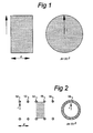
- a column of fluid (product) is considered of cylindrical cross section (figure 1).
- Different cross-sectional shapes give similar results.
- An electrode configuration that both has a suitable aperture through which product can be pumped and imposes a uniform electrical field distribution at the same time, is depicted in figures 2 en 3.
- each module should fixed to a circular equipotential. This requirement can be met by introducing circular shaped electrodes as depicted in figures 2 and 3.
- a uniform field across the array is also be obtained by changing the spacing di and cross-sectional area Ai of successive cells.
- the relative voltages on the electrodes may change the principle design of the treatment chamber remains the same. Apart from a uniform electrical field, an in- or decreasing field strength across the treatment chamber can be obtained.
- the voltages Ui imposed on the i-th electrode can be arbitrary as well as the distances di and cross-sections Ai.
- the radius of the electrode primarily depends on the minimum required cross-sectional area. This in turn depends on the required throughput of and the reological properties of the product.
- the choice in the number of modules and the separation distances of the electrodes depend on the electrical properties of the product, the required field strength and total treatment time.
- the total length of the treatment chamber is preferentially large in comparison to the radius of the circular electrodes.
- the electrical field distribution of the first and the last cell are slightly non-uniform. This is due to the fact that translation symmetry in the electrode array is absent.
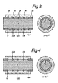
- the treatment chambers have cylindrical cross-sections and consist of 4 modules using 3 annular electrodes.
- the electrodes are spaced by electrical insulating material and contain the annular electrodes.
- the electrical connections of the electrode outward are not shown.
- the flow of product is in the direction of the imposed electrical field or head on to the electrical field depending on the choice of voltages.
- a pulsed voltage of magnitude U is used at the most left electrode.
- the voltage at the successive electrodes gradually decreases towards the right side.
- the electrode array is connected to a tube. This tube may be part of an auxiliary fluid handling system.
- the tubes are assumed to be of metal with high electrical conductivity and acts as an anode and cathode.
- circular electrodes with a circular cross-section (figure 4) the risk of Corona emission due to local field maxima at the insulator-electrode-product interfaces is reduced.
Landscapes
- Life Sciences & Earth Sciences (AREA)
- Engineering & Computer Science (AREA)
- Chemical & Material Sciences (AREA)
- Health & Medical Sciences (AREA)
- Veterinary Medicine (AREA)
- Hydrology & Water Resources (AREA)
- Polymers & Plastics (AREA)
- Zoology (AREA)
- Epidemiology (AREA)
- Animal Behavior & Ethology (AREA)
- General Health & Medical Sciences (AREA)
- Public Health (AREA)
- Wood Science & Technology (AREA)
- Food Science & Technology (AREA)
- Environmental & Geological Engineering (AREA)
- Water Supply & Treatment (AREA)
- Organic Chemistry (AREA)
- Food Preservation Except Freezing, Refrigeration, And Drying (AREA)
- Physical Or Chemical Processes And Apparatus (AREA)
- Apparatus For Disinfection Or Sterilisation (AREA)
- Disintegrating Or Milling (AREA)
- Finger-Pressure Massage (AREA)
- Electrotherapy Devices (AREA)
- Magnetic Treatment Devices (AREA)
Abstract
Description
- The invention relates to a treatment chamber in which a homogeneous pulsed electrical field is generated inside a pumpable product. This product is pumped continuously through the chamber in which a treatment is performed. Application of so-called pulsed electrical field treatment is used as a mild preservation method for foodstuffs and pharmaceuticals. In addition to preservation it also can be used to invoke pores in membranes of cellular structures to promote the transport of (macro-) molecular components across the membrane.
- The application, process description and several embodiments of so-called pulsed electrical field (PEF) treatment chambers for mild preservation have been discussed in literature. Examples can be found in US patents US-5.690.978, US-5.662.031, US-5.447.733, US-5.235.905, DE-3.708.775 and US 3 679 556. The treatment can be performed by pumping the product through a chamber in which an intense pulsed electrical field is generated. In case treatment is applied as a mild preservation method it seems that most vegetative micro organisms (bacteria, yeasts and fungi) are inactivated at a level of typically 30 kV/cm at temperatures that are less than required in a conventional heat pasteurisation process. After treatment the organisms have been found not to reproduce. The total time of a treatment depends on the pulse duration and shape, the total number of impulses that are applied during the residence time in the treatment zone and the volume flow rate of product through the chamber. In order to achieve a sufficient intense field strength temporarily, high voltage pulses of typically microsecond duration are generated in an auxiliary electronic pulse generating system.
- The total duration of the treatment is typical in the range of 10-300 microseconds and depends on the specific application. When electrical pulse treatment is performed as a mild preservation method the required reduction of microbiological counts, the type of product and the specific contamination have to be considered. It is preferred to apply several pulses within the treatment zone. High electrical fields should be imposed typically for a total duration in the range of 2 to 200 microseconds. For other field of applications of a treatment, as e.g. the enhancement of induced mass transport through biological membranes by electroporation, the required electrical field strength is in general less than 30 kV/cm.
- The electrical fields are imposed to the product using an electrode structure to which high voltage pulses are applied. The electrodes are in physical contact with the product and are contained in a mechanical construction through which the product is pumped. The combination of the electrodes, electrically isolating holders and sealing is referred to as treatment chamber. When produce is pumped through this chamber a treatment is performed in the resident period by applying short high voltage pulses to the electrodes at a sufficiently high rate.
- In this specification a system is considered where a product is pumped through a treatment chamber and where a stationary state in product flow and temperature is reached. In principle, no stationary conditions can be met since pulses are repeatedly applied in the process. However, the energy input by the short electrical pulses can be time averaged. In practise steady state flow and temperature conditions can be reached. In this discussion is denoted as the volume flow rate of the product and V the effective volume of the treatment chamber. The average residence time t of a fluid element in the device is given by t=V/. In this time the pulse treatment takes place. The required electrical peak power in treatment is given by Pp=σE2 V , where V denoted the effective volume of the treatment chamber, σ the mean product conductivity and E the average of the electrical field strength across the treatment device. The mean consumed electrical power is given by the relation Pc=σE2 τ where τ is the total treatment time of a fluid element. The latter is the total duration that a high electrical field is imposed on the transversing product. In case that square wave pulses are used with a duration τp the total treatment time is defined as τ=N*τp with N the mean number of pulses applied on the product when resident in the chamber.
- The electrical energy is converted into heat inside the product due to Ohmic heating. In general the temperature increase during treatment can be kept below 30 degrees centigrade. However, a small temperature increment results in a strong increase in electrical conductivity of the product. This is known to be the case for many different solutions containing minerals and for foodstuffs in particular. As an illustration: the electrical conductivity of a 0.75% KCl solution increases by more than 15 % in the temperature range of 18-25 degrees centigrade (CRC, Handbook of Chemistry and Physics, 72nd edition, 1991-1992).
- The required peak power for a treatment of a column of product with length L and cross-section A is given by P=σE2 AL=σE2 V in case a homogeneous electrical field distribution is assumed. For a column of product of conductivity a in which an electrical field is present with the direction along its length, the ohmic resistance is given by R=L/σA . In general only the real part of the electrical impedance is of importance. The parasitic capacity and self-inductance in a column of product is therefore neglected in this discussion.
- The geometry of the treatment chamber determines the largest possible size and shape of a channel through which the product can flow. In principle the size and shape of the channel should be such that the flow resistance is minimised. The magnitude of the electrical field strength and the uniformity of the electrical field distribution are not only determined by the dimensions of the chamber. Also the distribution of the electrical conductivity of the product across the treatment chamber should be considered.
- When a local current density of magnitude j is generated in a fluid element of electrical conductivity σ, an electrical field of strength E across the element is imposed. Its magnitude is given by j=σE (Ohms law). In practise it is important that all fluid elements that are pumped through a treatment chamber should receive a minimal treatment. That is, both the treatment time and the magnitude of the applied electrical field should be sufficiently high. The design of the treatment device and the electrode configuration determine how the electrical field strength is distributed in the product stream. It is preferred to create a uniform electrical field distribution across the treatment zone.
- In US patent US-5,235,905 a coaxial treatment device is considered. A major disadvantage of this design is the limited width of the annulus through which the product can flow. In addition it has relatively large electrode surfaces. US patent US-5.690.978 describes a co-linear treatment chamber. A disadvantage of the latter is its non-uniform distribution of the electrical field in the treatment zone. For a fixed diameter of this type of chamber a so-called gap distance has to be chosen. In case small gap distances (with respect to the diameter) are considered the electrical field distribution at the entrance and exit of the treatment zone is highly non-uniform. In case the gap distance is enlarged the non-uniformity in the field distribution is of less importance. However, in a treatment chamber with a large gap distance a fairly large temperature gradient will appear across the treatment zone at steady state conditions. This has a negative impact on the electrical field distribution across the fluid column inside the chamber. This is related to the fact that the electrical conductivity of products and solutions containing minerals in general are temperature dependent. The electrical conductivity for these products increases at higher temperatures. Due to the heat production in the chamber when receiving pulse treatment the temperature of the product at the exit of the treatment zone becomes higher than at the entrance. This leads to the built up of a gradient in the electrical conductivity across the treatment zone. As a result the voltage drop over the product column will change. This results in a smaller electrical field in the region near the exit of the treatment zone. The electrical field strength near the entrance will be higher. This treatment is however, over a much smaller region of the chamber volume and therefore lasts for a shorter period of time. As a result the spread in the effective field strength and spread in the treatment time in the product increases. This has an adverse affect on for example the degree of microbiological inactivation. In addition to this temperature induced effect the release of minerals and other components by cellular membrane structures will cause a similar effect. This can lead to a change in conductivity in the product across the treatment zone (for example: due to electroporation of biological membranes intracellular contents can be released).
- In patent US-5.690.978 the above-mentioned problem on the change of electrical conductivity over a product column is not recognised. However, this issue is of major importance as the direction of the electrical field strength is parallel to the flow direction and hence to a gradient in the electrical conductivity. In US-5.690.978 an extension of the number of treatment chambers in series is mentioned. The temperature increment across each individual treatment chamber in this system is of less importance. This is certainly the case when intermediate cooling is applied to remove the heat deposited in the product after each treatment. However, by increasing the number of treatment chambers with a small electrode gap distance the non-uniformity of the electrical field distribution remains.
- In this specification a novel modular design of a PEF treatment chamber is described comprising an open electrode structure with a large aperture. In this design the problem of non-uniformity due to a gradient in the product conductivity at steady state flow conditions is solved. The treatment chamber consists of several identical modules. Each module has a large aperture yet a small internal volume. By proper positioning of several of these modules the non-uniformity in the electrical field distribution of individual modules is compensated. As a result the overall electrical field strength of the treatment camber is uniform across the volume. As the different modules contain electrodes that can be connected to a certain voltage, the electrical field strength in all modules can be imposed individually.
- In general, for a given configuration of electrodes the electrical field can be found at every point by solving Laplace's equation for the given boundary conditions. The problem may include a gradient in conductivity. At this point a column of fluid (product) is considered of cylindrical cross section (figure 1). Different cross-sectional shapes give similar results. An electrode configuration that both has a suitable aperture through which product can be pumped and imposes a uniform electrical field distribution at the same time, is depicted in figures 2 en 3. This configuration consists of a sequence of modules (separated by a distance d and with cross-sectional area A) with a geometric volume V given by V=d*A. The boundaries of these modules are enclosed by circular shaped equipotentials. It has turned out that although the electrical field distribution of a single module is not uniform. However, in case that an array of properly coupled modules is considered a uniform field is obtained over the volume of each module.
- As mentioned the boundaries of each module should fixed to a circular equipotential. This requirement can be met by introducing circular shaped electrodes as depicted in figures 2 and 3.
- The voltage difference of the electrodes at the sides of the i-th module is given by Vi=E*d. The current density in the i-th cell of the array is given by ji=σi E. Note that the current density in successive cells can vary and dependant on the conductivity of the product is the i-th cel. The total electrical current in the i-th cell is given by I i = j i A. The electronic impedance of the i-th cell is given by Ri = d/σi A . If the voltage difference at the electrodes of successive modules increases by an amount on E*d, a uniform electrical field is obtained in the entire internal volume of the array.
- The required electrical peak power of the i-th cell is given by Pp,i=σi E2 Ad . The continuous power consumption by the i-th cell is given by Pc,i=σi E2 τ. By variation of voltage on the annular electrodes the electrical field in the i-th cell can be imposed electronically. To achieve a uniform electrical field across the treatment chamber, the voltage difference of successive annular electrodes is given by E*d. The total potential difference (Ut) across the treatment chamber is Ut=(n-1)*E*d , in case n electrodes are used.
- It should be noted that a uniform field across the array is also be obtained by changing the spacing di and cross-sectional area Ai of successive cells. Although the relative voltages on the electrodes may change the principle design of the treatment chamber remains the same. Apart from a uniform electrical field, an in- or decreasing field strength across the treatment chamber can be obtained. In general the voltages Ui imposed on the i-th electrode can be arbitrary as well as the distances di and cross-sections Ai.
- In the design of a practical treatment chamber a choice has to be made for the number of modules that is required, the radius of the electrodes and the separation distances. The radius of the electrode primarily depends on the minimum required cross-sectional area. This in turn depends on the required throughput of and the reological properties of the product. The choice in the number of modules and the separation distances of the electrodes depend on the electrical properties of the product, the required field strength and total treatment time. The total length of the treatment chamber is preferentially large in comparison to the radius of the circular electrodes. The electrical field distribution of the first and the last cell are slightly non-uniform. This is due to the fact that translation symmetry in the electrode array is absent.
- Examples of two practical designs of the above described treatment chamber are shown in figure 3 and 4. The treatment chambers have cylindrical cross-sections and consist of 4 modules using 3 annular electrodes. The electrodes are spaced by electrical insulating material and contain the annular electrodes. The electrical connections of the electrode outward are not shown. The flow of product is in the direction of the imposed electrical field or head on to the electrical field depending on the choice of voltages. In this example at the most left electrode a pulsed voltage of magnitude U is used. The voltage at the successive electrodes gradually decreases towards the right side. At the left-hand side and the right-hand side the electrode array is connected to a tube. This tube may be part of an auxiliary fluid handling system. In this example the tubes are assumed to be of metal with high electrical conductivity and acts as an anode and cathode. When using circular electrodes with a circular cross-section (figure 4) the risk of Corona emission due to local field maxima at the insulator-electrode-product interfaces is reduced.
- The advantages of the treatment chamber described in this patent are
- The aperture of each module has a large cross sectional area with respect to the contained volume
- The electrical field distribution is uniform even when a gradient in conductivity across the treatment device is present
- The construction of the treatment device is simple and can be easily cleaned.
- Due to its design the peak power that is needed can be distributed over several modules which can be fed by different auxiliary pulse power supplies
Claims (3)
- System for treating pumpable products by electrical pulses comprising:
at least one treatment chamber formed by at least two modules and comprising a flow channel through which product can be pumped,
an end electrode at the one end of the treatment chamber to which a low voltage has to be applied,
another end electrode at the other end of the chamber to which a high voltage has to be applied,
a generator circuit for generating voltage pulses to be applied to said electrodes,
characterized in that
the treatment chamber is provided with at least one intermediate electrode which is located in between said end electrodes and to which a voltage in between the voltages of the two end electrodes has to be applied. - System according to claim 1, characterized in that n intermediate electrodes are used in between the end electrodes whereby to each of the successive electrodes a voltage is applied, the level of which lies in between the voltages applied to the two neighbouring electrodes.
- System according to claim 2, characterized in that the mutual distance between the electrodes is in principle equal and that the voltages applied to the successive electrodes (using n electrodes) are defined as 0, U/(n+1), 2*U/(n+1), ..., n*U/(n+1), U.
Applications Claiming Priority (2)
| Application Number | Priority Date | Filing Date | Title |
|---|---|---|---|
| NL1010529A NL1010529C2 (en) | 1998-11-11 | 1998-11-11 | Integrated modular construction of a pulsed electrical field system. |
| NL1010529 | 1998-11-11 |
Publications (2)
| Publication Number | Publication Date |
|---|---|
| EP1000554A1 EP1000554A1 (en) | 2000-05-17 |
| EP1000554B1 true EP1000554B1 (en) | 2005-03-02 |
Family
ID=19768118
Family Applications (1)
| Application Number | Title | Priority Date | Filing Date |
|---|---|---|---|
| EP99203776A Expired - Lifetime EP1000554B1 (en) | 1998-11-11 | 1999-11-11 | Integrated modular design of a pulsed electrical field treatment chamber |
Country Status (7)
| Country | Link |
|---|---|
| US (1) | US6178880B1 (en) |
| EP (1) | EP1000554B1 (en) |
| AT (1) | ATE289755T1 (en) |
| CA (1) | CA2289829A1 (en) |
| DE (1) | DE69923912T2 (en) |
| ES (1) | ES2238811T3 (en) |
| NL (1) | NL1010529C2 (en) |
Cited By (17)
| Publication number | Priority date | Publication date | Assignee | Title |
|---|---|---|---|---|
| DE102005062933A1 (en) * | 2005-08-24 | 2007-03-22 | Triton Gmbh | A method of treating cellular structure in the meat, meat by-product, fish and seafood food processing industries |
| EP1852398A1 (en) * | 2006-03-08 | 2007-11-07 | Antomag s.r.l. | Method and apparatus for the treatment with electric current of polluted fluids |
| US7836543B2 (en) | 2006-02-10 | 2010-11-23 | Tennant Company | Method and apparatus for producing humanly-perceptable indicator of electrochemical properties of an output cleaning liquid |
| US7891046B2 (en) | 2006-02-10 | 2011-02-22 | Tennant Company | Apparatus for generating sparged, electrochemically activated liquid |
| US8007654B2 (en) | 2006-02-10 | 2011-08-30 | Tennant Company | Electrochemically activated anolyte and catholyte liquid |
| US8012340B2 (en) | 2006-02-10 | 2011-09-06 | Tennant Company | Method for generating electrochemically activated cleaning liquid |
| US8012339B2 (en) | 2006-02-10 | 2011-09-06 | Tennant Company | Hand-held spray bottle having an electrolyzer and method therefor |
| US8016996B2 (en) | 2006-02-10 | 2011-09-13 | Tennant Company | Method of producing a sparged cleaning liquid onboard a mobile surface cleaner |
| US8025786B2 (en) | 2006-02-10 | 2011-09-27 | Tennant Company | Method of generating sparged, electrochemically activated liquid |
| US8025787B2 (en) | 2006-02-10 | 2011-09-27 | Tennant Company | Method and apparatus for generating, applying and neutralizing an electrochemically activated liquid |
| US8046867B2 (en) | 2006-02-10 | 2011-11-01 | Tennant Company | Mobile surface cleaner having a sparging device |
| US8062499B2 (en) | 2008-05-05 | 2011-11-22 | Tennant Compnay | Charge movement detector for electrochemically activated liquids |
| US8236147B2 (en) | 2008-06-19 | 2012-08-07 | Tennant Company | Tubular electrolysis cell and corresponding method |
| US8319654B2 (en) | 2008-06-19 | 2012-11-27 | Tennant Company | Apparatus having electrolysis cell and indicator light illuminating through liquid |
| US8337690B2 (en) | 2007-10-04 | 2012-12-25 | Tennant Company | Method and apparatus for neutralizing electrochemically activated liquids |
| US8371315B2 (en) | 2008-12-17 | 2013-02-12 | Tennant Company | Washing systems incorporating charged activated liquids |
| US8485140B2 (en) | 2008-06-05 | 2013-07-16 | Global Patent Investment Group, LLC | Fuel combustion method and system |
Families Citing this family (17)
| Publication number | Priority date | Publication date | Assignee | Title |
|---|---|---|---|---|
| US6331321B1 (en) | 2000-04-25 | 2001-12-18 | John A. Robbins | Process and apparatus for reduction of microorganisms in a conductive medium using low voltage pulsed electrical energy |
| ES2167237B2 (en) * | 2000-05-18 | 2003-11-16 | Fundacion Inasmet | MICROORGANISM DESTRUCTION PROCEDURE. |
| NL1017942C2 (en) * | 2001-04-26 | 2002-10-29 | Kema Nv | Method and device for killing entomology. |
| SE520666C2 (en) * | 2001-12-19 | 2003-08-12 | Sik Inst Foer Livsmedel Och Bi | Method and apparatus for processing a pumpable food in an electric field |
| JP4997102B2 (en) * | 2004-05-07 | 2012-08-08 | ユニバーシティ オブ ウォータールー | Electrofluidic processing chamber |
| ITVI20050179A1 (en) * | 2005-06-21 | 2006-12-22 | Cartigliano Off Spa | APPARATUS FOR THE APPLICATION OF ELECTROMAGNETIC FIELDS OF OSCILLANTS, PARTICULARLY FOR THE TREATMENT OF PRODUCTS IN LIQUID, PASTOSOUS, SEMISOLID OR GRANULAR STATE, AS WELL AS THE METHOD OF USE OF THE SAME AND PLANT INCORPORATING SUCH EQUIPMENT |
| DE102006022611A1 (en) * | 2006-05-15 | 2007-11-22 | Siemens Ag | Method for eliminating the germination and replanting ability of animal and plant organisms and arrangement for carrying out the method |
| CA2762654C (en) * | 2008-09-23 | 2017-11-14 | Aseptia, Inc. | Electromagnetic system |
| EP2338356A1 (en) * | 2009-12-23 | 2011-06-29 | Südzucker Aktiengesellschaft Mannheim/Ochsenfurt | Reactor system for electroporation |
| NL1037939C2 (en) * | 2010-05-05 | 2011-11-08 | Ixl Nederland B V | METHOD RESP. SYSTEM FOR THE TREATMENT OF A NUTRITIONAL FOODSTUFF. |
| US8651015B2 (en) * | 2011-08-20 | 2014-02-18 | Zhejiang Haochuang Biotech Co., Inc. | Electronic sterilization device and method |
| NZ630085A (en) * | 2012-03-20 | 2016-04-29 | Stichting Dienst Landbouwkundi | Process for fast and homogeneously heating a liquid product and apparatus for such process |
| CN104171767A (en) * | 2014-08-08 | 2014-12-03 | 江南大学 | High-voltage pulsed electric field sterilizing system coaxial processing chamber with adjustable runner shape |
| CN205161795U9 (en) | 2015-10-23 | 2018-09-04 | 浙江好创生物技术有限公司 | A kind of sterilizing of electron spray and protein peptide bond fracturing device |
| US10557131B2 (en) * | 2016-07-07 | 2020-02-11 | National Agriculture And Food Research Organization | Method of producing yeast extract |
| EP3985099A4 (en) * | 2019-07-12 | 2022-08-17 | FUJIFILM Corporation | Production method of organism-derived substance, production method of product, and voltage application device |
| CN211770461U (en) * | 2019-09-11 | 2020-10-27 | Arc阿罗马珀尔公司 | Pulsed electric field chamber |
Family Cites Families (10)
| Publication number | Priority date | Publication date | Assignee | Title |
|---|---|---|---|---|
| DE1667029A1 (en) * | 1967-09-26 | 1972-02-17 | Richard Eifert Wirtschaftsprue | Method and device for the treatment of disperse systems |
| US5235905A (en) * | 1985-05-31 | 1993-08-17 | Foodco Corporation | High pulsed voltage systems for extending the shelf life of pumpable food products |
| US5048404A (en) * | 1985-05-31 | 1991-09-17 | Foodco Corporation | High pulsed voltage systems for extending the shelf life of pumpable food products |
| US4695472A (en) * | 1985-05-31 | 1987-09-22 | Maxwell Laboratories, Inc. | Methods and apparatus for extending the shelf life of fluid food products |
| US5031521A (en) * | 1989-03-27 | 1991-07-16 | Grishko Alexei A | Electroplasmolyzer for processing plant raw material |
| US5447733A (en) * | 1994-01-06 | 1995-09-05 | Purepulse Technologies, Inc. | Prevention of electrochemical and electrophoretic effects in high-strength-electric-field pumpable-food-product treatment systems |
| DK174057B1 (en) * | 1994-08-17 | 2002-05-13 | Tulip Internat A S | Method and apparatus for heating media by high frequency electromagnetic waves |
| US5662031A (en) * | 1994-12-23 | 1997-09-02 | Washington State University Research Foundation, Inc. | Continuous flow electrical treatment of flowable food products |
| US5514391A (en) * | 1995-06-07 | 1996-05-07 | Pure Pulse Technologies | Process for reducing levels of microorganisms in pumpable food products using a high pulsed voltage system |
| US5690978A (en) * | 1996-09-30 | 1997-11-25 | Ohio State University | High voltage pulsed electric field treatment chambers for the preservation of liquid food products |
-
1998
- 1998-11-11 NL NL1010529A patent/NL1010529C2/en not_active IP Right Cessation
-
1999
- 1999-11-11 AT AT99203776T patent/ATE289755T1/en not_active IP Right Cessation
- 1999-11-11 EP EP99203776A patent/EP1000554B1/en not_active Expired - Lifetime
- 1999-11-11 ES ES99203776T patent/ES2238811T3/en not_active Expired - Lifetime
- 1999-11-11 DE DE69923912T patent/DE69923912T2/en not_active Expired - Fee Related
- 1999-11-12 US US09/438,946 patent/US6178880B1/en not_active Expired - Fee Related
- 1999-11-12 CA CA002289829A patent/CA2289829A1/en not_active Abandoned
Cited By (20)
| Publication number | Priority date | Publication date | Assignee | Title |
|---|---|---|---|---|
| DE102005062933A1 (en) * | 2005-08-24 | 2007-03-22 | Triton Gmbh | A method of treating cellular structure in the meat, meat by-product, fish and seafood food processing industries |
| US8046867B2 (en) | 2006-02-10 | 2011-11-01 | Tennant Company | Mobile surface cleaner having a sparging device |
| US8025786B2 (en) | 2006-02-10 | 2011-09-27 | Tennant Company | Method of generating sparged, electrochemically activated liquid |
| US7891046B2 (en) | 2006-02-10 | 2011-02-22 | Tennant Company | Apparatus for generating sparged, electrochemically activated liquid |
| US8603320B2 (en) | 2006-02-10 | 2013-12-10 | Tennant Company | Mobile surface cleaner and method for generating and applying an electrochemically activated sanitizing liquid having O3 molecules |
| US8012340B2 (en) | 2006-02-10 | 2011-09-06 | Tennant Company | Method for generating electrochemically activated cleaning liquid |
| US8012339B2 (en) | 2006-02-10 | 2011-09-06 | Tennant Company | Hand-held spray bottle having an electrolyzer and method therefor |
| US8016996B2 (en) | 2006-02-10 | 2011-09-13 | Tennant Company | Method of producing a sparged cleaning liquid onboard a mobile surface cleaner |
| US8719999B2 (en) | 2006-02-10 | 2014-05-13 | Tennant Company | Method and apparatus for cleaning surfaces with high pressure electrolyzed fluid |
| US7836543B2 (en) | 2006-02-10 | 2010-11-23 | Tennant Company | Method and apparatus for producing humanly-perceptable indicator of electrochemical properties of an output cleaning liquid |
| US8025787B2 (en) | 2006-02-10 | 2011-09-27 | Tennant Company | Method and apparatus for generating, applying and neutralizing an electrochemically activated liquid |
| US8007654B2 (en) | 2006-02-10 | 2011-08-30 | Tennant Company | Electrochemically activated anolyte and catholyte liquid |
| US8156608B2 (en) | 2006-02-10 | 2012-04-17 | Tennant Company | Cleaning apparatus having a functional generator for producing electrochemically activated cleaning liquid |
| EP1852398A1 (en) * | 2006-03-08 | 2007-11-07 | Antomag s.r.l. | Method and apparatus for the treatment with electric current of polluted fluids |
| US8337690B2 (en) | 2007-10-04 | 2012-12-25 | Tennant Company | Method and apparatus for neutralizing electrochemically activated liquids |
| US8062499B2 (en) | 2008-05-05 | 2011-11-22 | Tennant Compnay | Charge movement detector for electrochemically activated liquids |
| US8485140B2 (en) | 2008-06-05 | 2013-07-16 | Global Patent Investment Group, LLC | Fuel combustion method and system |
| US8319654B2 (en) | 2008-06-19 | 2012-11-27 | Tennant Company | Apparatus having electrolysis cell and indicator light illuminating through liquid |
| US8236147B2 (en) | 2008-06-19 | 2012-08-07 | Tennant Company | Tubular electrolysis cell and corresponding method |
| US8371315B2 (en) | 2008-12-17 | 2013-02-12 | Tennant Company | Washing systems incorporating charged activated liquids |
Also Published As
| Publication number | Publication date |
|---|---|
| ATE289755T1 (en) | 2005-03-15 |
| NL1010529C2 (en) | 2000-05-15 |
| CA2289829A1 (en) | 2000-05-11 |
| DE69923912T2 (en) | 2006-02-16 |
| ES2238811T3 (en) | 2005-09-01 |
| EP1000554A1 (en) | 2000-05-17 |
| US6178880B1 (en) | 2001-01-30 |
| DE69923912D1 (en) | 2005-04-07 |
Similar Documents
| Publication | Publication Date | Title |
|---|---|---|
| EP1000554B1 (en) | Integrated modular design of a pulsed electrical field treatment chamber | |
| CA2459475C (en) | Method and reactor for the non-thermal decomposition and pasteurization of organic process materials by electroporation | |
| US12415998B2 (en) | Method and device for uniformly treating adherent cells | |
| AU669725B2 (en) | High pulsed voltage systems for extending the shelf life of pumpable food products | |
| US5326530A (en) | Energy-efficient electromagnetic elimination of noxious biological organisms | |
| US4457221A (en) | Sterilization apparatus | |
| EP0553377A1 (en) | Energy-efficient electromagnetic elimination of noxious biological organisms | |
| EP1028635A4 (en) | TREATMENT CHAMBERS BASED ON HIGH VOLTAGE PULSED ELECTRIC FIELD FOR MAINTAINING LIQUID FOODS | |
| US6393975B2 (en) | Treatment apparatus and method for preserving pumpable food products in a pulsed electric field | |
| AU2003223351A1 (en) | Method of treating biological materials with translating electrical fields and electrode polarity reversal | |
| DE4434039A1 (en) | Method and device for heating food products by electric heating using a low-frequency current | |
| CA2497649A1 (en) | Apparatus and method for streaming electroporation | |
| CA1287597C (en) | Electric-impulse method for treating substances and device for carryingout the method | |
| US6077479A (en) | Apparatus for the disinfection of liquids | |
| JPH0646830A (en) | Large-scale processing electrode for electric cell fusion and electric nucleic acid introduction | |
| JP2010512150A (en) | Transfection in electronically driven continuous flow | |
| Sack et al. | Design considerations for electroporation reactors | |
| JP6418649B2 (en) | Reactor device for electroporation | |
| JP2004066055A (en) | Liquid treatment equipment | |
| EP0097645A1 (en) | Sterilization process and apparatus | |
| Kurcevskis et al. | High Power Electroporation System in Food Treatment-Review | |
| WO2012127423A1 (en) | Method and apparatus for treating fluids containing biological pollutants with an electric field | |
| Prins et al. | Solid state pulsed power source for pulsed electric field and plasma treatment of food products | |
| JP2001017135A (en) | Sterilizing device for liquid state material | |
| US20130341193A1 (en) | Device for the Treatment of a Product By A Pulsed Electric Field |
Legal Events
| Date | Code | Title | Description |
|---|---|---|---|
| PUAI | Public reference made under article 153(3) epc to a published international application that has entered the european phase |
Free format text: ORIGINAL CODE: 0009012 |
|
| AK | Designated contracting states |
Kind code of ref document: A1 Designated state(s): AT BE CH CY DE DK ES FI FR GB GR IE IT LI LU MC NL PT SE |
|
| AX | Request for extension of the european patent |
Free format text: AL;LT;LV;MK;RO;SI |
|
| 17P | Request for examination filed |
Effective date: 20001110 |
|
| AKX | Designation fees paid |
Free format text: AT BE CH CY DE DK ES FI FR GB GR IE IT LI LU MC NL PT SE |
|
| GRAP | Despatch of communication of intention to grant a patent |
Free format text: ORIGINAL CODE: EPIDOSNIGR1 |
|
| GRAS | Grant fee paid |
Free format text: ORIGINAL CODE: EPIDOSNIGR3 |
|
| GRAA | (expected) grant |
Free format text: ORIGINAL CODE: 0009210 |
|
| AK | Designated contracting states |
Kind code of ref document: B1 Designated state(s): AT BE CH CY DE DK ES FI FR GB GR IE IT LI LU MC NL PT SE |
|
| PG25 | Lapsed in a contracting state [announced via postgrant information from national office to epo] |
Ref country code: LI Free format text: LAPSE BECAUSE OF FAILURE TO SUBMIT A TRANSLATION OF THE DESCRIPTION OR TO PAY THE FEE WITHIN THE PRESCRIBED TIME-LIMIT Effective date: 20050302 Ref country code: IT Free format text: LAPSE BECAUSE OF FAILURE TO SUBMIT A TRANSLATION OF THE DESCRIPTION OR TO PAY THE FEE WITHIN THE PRESCRIBED TIME-LIMIT;WARNING: LAPSES OF ITALIAN PATENTS WITH EFFECTIVE DATE BEFORE 2007 MAY HAVE OCCURRED AT ANY TIME BEFORE 2007. THE CORRECT EFFECTIVE DATE MAY BE DIFFERENT FROM THE ONE RECORDED. Effective date: 20050302 Ref country code: FI Free format text: LAPSE BECAUSE OF FAILURE TO SUBMIT A TRANSLATION OF THE DESCRIPTION OR TO PAY THE FEE WITHIN THE PRESCRIBED TIME-LIMIT Effective date: 20050302 Ref country code: CH Free format text: LAPSE BECAUSE OF FAILURE TO SUBMIT A TRANSLATION OF THE DESCRIPTION OR TO PAY THE FEE WITHIN THE PRESCRIBED TIME-LIMIT Effective date: 20050302 Ref country code: BE Free format text: LAPSE BECAUSE OF FAILURE TO SUBMIT A TRANSLATION OF THE DESCRIPTION OR TO PAY THE FEE WITHIN THE PRESCRIBED TIME-LIMIT Effective date: 20050302 Ref country code: AT Free format text: LAPSE BECAUSE OF FAILURE TO SUBMIT A TRANSLATION OF THE DESCRIPTION OR TO PAY THE FEE WITHIN THE PRESCRIBED TIME-LIMIT Effective date: 20050302 |
|
| REG | Reference to a national code |
Ref country code: GB Ref legal event code: FG4D |
|
| REG | Reference to a national code |
Ref country code: CH Ref legal event code: EP |
|
| REG | Reference to a national code |
Ref country code: IE Ref legal event code: FG4D |
|
| REF | Corresponds to: |
Ref document number: 69923912 Country of ref document: DE Date of ref document: 20050407 Kind code of ref document: P |
|
| RAP2 | Party data changed (patent owner data changed or rights of a patent transferred) |
Owner name: AGROTECHNOLOGY AND FOOD INNOVATIONS B.V. |
|
| PG25 | Lapsed in a contracting state [announced via postgrant information from national office to epo] |
Ref country code: GR Free format text: LAPSE BECAUSE OF FAILURE TO SUBMIT A TRANSLATION OF THE DESCRIPTION OR TO PAY THE FEE WITHIN THE PRESCRIBED TIME-LIMIT Effective date: 20050602 Ref country code: DK Free format text: LAPSE BECAUSE OF FAILURE TO SUBMIT A TRANSLATION OF THE DESCRIPTION OR TO PAY THE FEE WITHIN THE PRESCRIBED TIME-LIMIT Effective date: 20050602 |
|
| NLT2 | Nl: modifications (of names), taken from the european patent patent bulletin |
Owner name: AGROTECHNOLOGY AND FOOD INNOVATIONS B.V. |
|
| PG25 | Lapsed in a contracting state [announced via postgrant information from national office to epo] |
Ref country code: PT Free format text: LAPSE BECAUSE OF FAILURE TO SUBMIT A TRANSLATION OF THE DESCRIPTION OR TO PAY THE FEE WITHIN THE PRESCRIBED TIME-LIMIT Effective date: 20050817 |
|
| REG | Reference to a national code |
Ref country code: ES Ref legal event code: FG2A Ref document number: 2238811 Country of ref document: ES Kind code of ref document: T3 |
|
| REG | Reference to a national code |
Ref country code: CH Ref legal event code: PL |
|
| ET | Fr: translation filed | ||
| PG25 | Lapsed in a contracting state [announced via postgrant information from national office to epo] |
Ref country code: IE Free format text: LAPSE BECAUSE OF NON-PAYMENT OF DUE FEES Effective date: 20051111 Ref country code: CY Free format text: LAPSE BECAUSE OF FAILURE TO SUBMIT A TRANSLATION OF THE DESCRIPTION OR TO PAY THE FEE WITHIN THE PRESCRIBED TIME-LIMIT Effective date: 20051111 |
|
| PGFP | Annual fee paid to national office [announced via postgrant information from national office to epo] |
Ref country code: GB Payment date: 20051116 Year of fee payment: 7 |
|
| PGFP | Annual fee paid to national office [announced via postgrant information from national office to epo] |
Ref country code: DE Payment date: 20051124 Year of fee payment: 7 |
|
| PGFP | Annual fee paid to national office [announced via postgrant information from national office to epo] |
Ref country code: FR Payment date: 20051125 Year of fee payment: 7 |
|
| PGFP | Annual fee paid to national office [announced via postgrant information from national office to epo] |
Ref country code: ES Payment date: 20051129 Year of fee payment: 7 |
|
| PG25 | Lapsed in a contracting state [announced via postgrant information from national office to epo] |
Ref country code: MC Free format text: LAPSE BECAUSE OF NON-PAYMENT OF DUE FEES Effective date: 20051130 Ref country code: LU Free format text: LAPSE BECAUSE OF NON-PAYMENT OF DUE FEES Effective date: 20051130 |
|
| PGFP | Annual fee paid to national office [announced via postgrant information from national office to epo] |
Ref country code: NL Payment date: 20051130 Year of fee payment: 7 |
|
| PLBE | No opposition filed within time limit |
Free format text: ORIGINAL CODE: 0009261 |
|
| STAA | Information on the status of an ep patent application or granted ep patent |
Free format text: STATUS: NO OPPOSITION FILED WITHIN TIME LIMIT |
|
| 26N | No opposition filed |
Effective date: 20051205 |
|
| REG | Reference to a national code |
Ref country code: IE Ref legal event code: MM4A |
|
| PG25 | Lapsed in a contracting state [announced via postgrant information from national office to epo] |
Ref country code: NL Free format text: LAPSE BECAUSE OF NON-PAYMENT OF DUE FEES Effective date: 20070601 Ref country code: DE Free format text: LAPSE BECAUSE OF NON-PAYMENT OF DUE FEES Effective date: 20070601 |
|
| GBPC | Gb: european patent ceased through non-payment of renewal fee |
Effective date: 20061111 |
|
| NLV4 | Nl: lapsed or anulled due to non-payment of the annual fee |
Effective date: 20070601 |
|
| REG | Reference to a national code |
Ref country code: FR Ref legal event code: ST Effective date: 20070731 |
|
| PG25 | Lapsed in a contracting state [announced via postgrant information from national office to epo] |
Ref country code: GB Free format text: LAPSE BECAUSE OF NON-PAYMENT OF DUE FEES Effective date: 20061111 |
|
| PG25 | Lapsed in a contracting state [announced via postgrant information from national office to epo] |
Ref country code: SE Free format text: LAPSE BECAUSE OF FAILURE TO SUBMIT A TRANSLATION OF THE DESCRIPTION OR TO PAY THE FEE WITHIN THE PRESCRIBED TIME-LIMIT Effective date: 20050602 |
|
| REG | Reference to a national code |
Ref country code: ES Ref legal event code: FD2A Effective date: 20061113 |
|
| PG25 | Lapsed in a contracting state [announced via postgrant information from national office to epo] |
Ref country code: FR Free format text: LAPSE BECAUSE OF NON-PAYMENT OF DUE FEES Effective date: 20061130 Ref country code: ES Free format text: LAPSE BECAUSE OF NON-PAYMENT OF DUE FEES Effective date: 20061113 |