EP1000273B1 - Fluid mount including a partitionless compensator - Google Patents
Fluid mount including a partitionless compensator Download PDFInfo
- Publication number
- EP1000273B1 EP1000273B1 EP98938298A EP98938298A EP1000273B1 EP 1000273 B1 EP1000273 B1 EP 1000273B1 EP 98938298 A EP98938298 A EP 98938298A EP 98938298 A EP98938298 A EP 98938298A EP 1000273 B1 EP1000273 B1 EP 1000273B1
- Authority
- EP
- European Patent Office
- Prior art keywords
- fluid
- mounting
- compensator
- chamber
- lock
- Prior art date
- Legal status (The legal status is an assumption and is not a legal conclusion. Google has not performed a legal analysis and makes no representation as to the accuracy of the status listed.)
- Expired - Lifetime
Links
- 239000012530 fluid Substances 0.000 title claims description 93
- 229920001971 elastomer Polymers 0.000 claims description 12
- 239000000806 elastomer Substances 0.000 claims description 12
- 238000010276 construction Methods 0.000 claims description 5
- 230000004888 barrier function Effects 0.000 claims description 3
- 239000011521 glass Substances 0.000 claims description 2
- 238000013016 damping Methods 0.000 description 5
- 230000033001 locomotion Effects 0.000 description 4
- 238000000034 method Methods 0.000 description 3
- 244000043261 Hevea brasiliensis Species 0.000 description 2
- 230000004075 alteration Effects 0.000 description 2
- 230000005540 biological transmission Effects 0.000 description 2
- 230000000694 effects Effects 0.000 description 2
- 239000000463 material Substances 0.000 description 2
- 238000012986 modification Methods 0.000 description 2
- 230000004048 modification Effects 0.000 description 2
- 229920003052 natural elastomer Polymers 0.000 description 2
- 229920001194 natural rubber Polymers 0.000 description 2
- 239000004721 Polyphenylene oxide Substances 0.000 description 1
- 230000006978 adaptation Effects 0.000 description 1
- 230000003416 augmentation Effects 0.000 description 1
- 238000002955 isolation Methods 0.000 description 1
- 239000000203 mixture Substances 0.000 description 1
- 238000005192 partition Methods 0.000 description 1
- 229920000570 polyether Polymers 0.000 description 1
- 229920001296 polysiloxane Polymers 0.000 description 1
Images


Classifications
-
- F—MECHANICAL ENGINEERING; LIGHTING; HEATING; WEAPONS; BLASTING
- F16—ENGINEERING ELEMENTS AND UNITS; GENERAL MEASURES FOR PRODUCING AND MAINTAINING EFFECTIVE FUNCTIONING OF MACHINES OR INSTALLATIONS; THERMAL INSULATION IN GENERAL
- F16F—SPRINGS; SHOCK-ABSORBERS; MEANS FOR DAMPING VIBRATION
- F16F9/00—Springs, vibration-dampers, shock-absorbers, or similarly-constructed movement-dampers using a fluid or the equivalent as damping medium
- F16F9/06—Springs, vibration-dampers, shock-absorbers, or similarly-constructed movement-dampers using a fluid or the equivalent as damping medium using both gas and liquid
- F16F9/066—Units characterised by the partition, baffle or like element
-
- F—MECHANICAL ENGINEERING; LIGHTING; HEATING; WEAPONS; BLASTING
- F16—ENGINEERING ELEMENTS AND UNITS; GENERAL MEASURES FOR PRODUCING AND MAINTAINING EFFECTIVE FUNCTIONING OF MACHINES OR INSTALLATIONS; THERMAL INSULATION IN GENERAL
- F16F—SPRINGS; SHOCK-ABSORBERS; MEANS FOR DAMPING VIBRATION
- F16F1/00—Springs
- F16F1/36—Springs made of rubber or other material having high internal friction, e.g. thermoplastic elastomers
- F16F1/38—Springs made of rubber or other material having high internal friction, e.g. thermoplastic elastomers with a sleeve of elastic material between a rigid outer sleeve and a rigid inner sleeve or pin, i.e. bushing-type
-
- F—MECHANICAL ENGINEERING; LIGHTING; HEATING; WEAPONS; BLASTING
- F16—ENGINEERING ELEMENTS AND UNITS; GENERAL MEASURES FOR PRODUCING AND MAINTAINING EFFECTIVE FUNCTIONING OF MACHINES OR INSTALLATIONS; THERMAL INSULATION IN GENERAL
- F16F—SPRINGS; SHOCK-ABSORBERS; MEANS FOR DAMPING VIBRATION
- F16F13/00—Units comprising springs of the non-fluid type as well as vibration-dampers, shock-absorbers, or fluid springs
- F16F13/04—Units comprising springs of the non-fluid type as well as vibration-dampers, shock-absorbers, or fluid springs comprising both a plastics spring and a damper, e.g. a friction damper
- F16F13/06—Units comprising springs of the non-fluid type as well as vibration-dampers, shock-absorbers, or fluid springs comprising both a plastics spring and a damper, e.g. a friction damper the damper being a fluid damper, e.g. the plastics spring not forming a part of the wall of the fluid chamber of the damper
- F16F13/08—Units comprising springs of the non-fluid type as well as vibration-dampers, shock-absorbers, or fluid springs comprising both a plastics spring and a damper, e.g. a friction damper the damper being a fluid damper, e.g. the plastics spring not forming a part of the wall of the fluid chamber of the damper the plastics spring forming at least a part of the wall of the fluid chamber of the damper
- F16F13/18—Units comprising springs of the non-fluid type as well as vibration-dampers, shock-absorbers, or fluid springs comprising both a plastics spring and a damper, e.g. a friction damper the damper being a fluid damper, e.g. the plastics spring not forming a part of the wall of the fluid chamber of the damper the plastics spring forming at least a part of the wall of the fluid chamber of the damper characterised by the location or the shape of the equilibration chamber, e.g. the equilibration chamber, surrounding the plastics spring or being annular
-
- F—MECHANICAL ENGINEERING; LIGHTING; HEATING; WEAPONS; BLASTING
- F16—ENGINEERING ELEMENTS AND UNITS; GENERAL MEASURES FOR PRODUCING AND MAINTAINING EFFECTIVE FUNCTIONING OF MACHINES OR INSTALLATIONS; THERMAL INSULATION IN GENERAL
- F16F—SPRINGS; SHOCK-ABSORBERS; MEANS FOR DAMPING VIBRATION
- F16F13/00—Units comprising springs of the non-fluid type as well as vibration-dampers, shock-absorbers, or fluid springs
- F16F13/04—Units comprising springs of the non-fluid type as well as vibration-dampers, shock-absorbers, or fluid springs comprising both a plastics spring and a damper, e.g. a friction damper
- F16F13/06—Units comprising springs of the non-fluid type as well as vibration-dampers, shock-absorbers, or fluid springs comprising both a plastics spring and a damper, e.g. a friction damper the damper being a fluid damper, e.g. the plastics spring not forming a part of the wall of the fluid chamber of the damper
- F16F13/24—Units comprising springs of the non-fluid type as well as vibration-dampers, shock-absorbers, or fluid springs comprising both a plastics spring and a damper, e.g. a friction damper the damper being a fluid damper, e.g. the plastics spring not forming a part of the wall of the fluid chamber of the damper the central part of the unit being supported by one element and both extremities of the unit being supported by a single other element, i.e. double acting mounting
Definitions
- This invention relates to devices for controlling dynamic vibration. Specifically, it relates to fluid mountings for control of vibration between a vibrating member and structure.
- Fluid or hydraulic mountings include a fluid which augments isolation and / or damping characteristics that may be achieved in elastomer mountings alone. This augmentation may take the form of adding additional damping or added inertial forces. Fluid mountings are generally described in LORD® Technical Article LL-2166 entitled "Understanding Hydraulic Mounts for Improved Vehicle Noise, Vibration and Ride Qualities" by W. C. Flower. Commonly assigned US Pat. No. 4,811,919 to Jones describes a fluid mounting which incorporates a volume compensator. Other examples of fluid mountings and dampers may be found in commonly assigned US Pat. Nos.
- Fluid mountings are, in essence, tunable passive devices which use a fluid to add additional damping or tuned-fluid "inertia" effects. In all these devices, compensation of fluid expansion, pressurization, and fill to remove air bubbles is a problem.
- prior art methods of accomplishing these feats have involved utilization of multi-component systems which tend to add unwanted cost and complexity.
- US Pat. No. 5,540,549 describes an inner and outer member which are flexibly supported relative to one another. A piston is attached to the inner member and movement of the piston within a fluid cavity causes a damping force.
- the present invention is a fluid mounting adapted for attachment between a vibrating member and a structure for isolating or damping vibration therebetween.
- a first aspect of the present invention consists in:
- a bubble trap formed in a wall portion of one of said chambers focuses any bubbles present into said at least one lock passage.
- the bubble trap is an annular groove formed by cooperation between a chamfer formed on a plug hole chamber and a chamfer formed on a plug received within said plug hole.
- a plurality of lock passages increase the speed at which bubbles enter the compensator chamber.
- an extension within the volume compensator extends part way into the compensator chamber and includes an opening cooperating with the lock passageway(s). The opening is always covered by the fluid regardless of an orientation of said mounting. This prevents air, once it leaves the operating chambers, from getting back in.
- the flexible element includes laminated construction which includes at least one rigid shim and at least two elastomer layers.
- Each of the at least two elastomer layers including a sloping end portion, one of which intersects with an end of said at least one rigid shim and another which intersects with an end of said inner member, thereby preventing air bubbles from becoming trapped. This aids in fill of the mounting.
- the partitionless compensator eliminates one or more components from the fluid mounting.
- Fig. 1a shown generally at 20, is a first embodiment of the fluid mounting including a partitionless compensator 36.
- the fluid mounting 20 is useful for controlling, and preferably minimizing, dynamic vibration (motion and/or force) transmitted between a vibrating member 21 , such as an helicopter transmission or the like, and a structure 23 , such as an aircraft fuselage, or the like.
- a vibrating member 21 such as an helicopter transmission or the like
- a structure 23 such as an aircraft fuselage, or the like.
- the fluid mounting 20 comprises an elongated rigid inner member 22 adapted for interconnection to a first member 21 such as a structure, for example, a helicopter fuselage, and an outer member 24 adapted to be attached to a second member 23 b, such as a vibrating element, for example, a helicopter transmission or pylon.
- a flexible elastomer element 26 flexibly supports the inner member 22 relative to the outer member 24 .
- Preferable materials include natural rubber, natural rubber and synthetic blends. Although, other suitable elastomers or flexible materials could also be used.
- the elastomer section may include laminated construction.
- First 28 and second 30 operating chambers are formed within the mounting 20 , each of which interacts with end portions of the flexible elastomer section 26 .
- a fluid passageway 32 which may include a tuned fluid inertia (resonant mass effect) interconnects the first and second operating chambers 28, 30.
- a fluid 34 is oscillated back and forth through passageway 32 as a result of dynamic vibrations between the inner member 22 and outer member 24.
- a partitionless volume compensator 36 attaches to a portion of the outer member 24 .
- the partitionless compensator 36 includes a compensator chamber 38 including a gas-filled portion 40 and a fluid-filled portion 42 .
- the gas-filled portion 40 overlies the fluid-filled portion 42 and the chamber 38 is devoid of any barrier separating the portions 40, 42 .
- Prior art compensators for fluid mounts include a flexible partition, for example, as is shown in US Pat. No. 4,811,919 to Jones. An additional example may be found in copending application 08/533,227 entitled "High Temperature Fluid Mount".
- At least one lock passage 44 interconnects between the fluid-filled portion 42 of chamber 38 and one of the first and second operating chambers 28, 30 .
- the lock passage 44 is of the appropriate length and diameter such that flow is minimized at the predominant operating frequency of the mounting, i.e., the passage is locked.
- a fluid 34 such as silicone or perfluorinated polyether is contained within the first and second operating chambers 28, 30 , the fluid passageway 32 , the fluid-filled portion 42 , and the at least one lock passage 44 .
- the viscosity of the fluid 34 is relevant to the operation of the invention.
- the mounting also includes a bubble trap 46 formed in a wall portion 48 of one of said chambers 28, 30 .
- the bubble trap 46 is an irregularity formed in the surface which focuses any bubbles present into the at least one lock passage 44 .
- the surface leading to the bubble trap preferably includes a taper or incline.
- the bubble trap 46 is an annular groove formed into a wall portion of the first operating chamber 28.
- the bubble trap 46 is formed by cooperation between a chamfer 52 formed on a plug hole 50 interconnecting between the compensator chamber 38 and one of the operating chambers 28, 30 and a chamfer 52' formed on a plug 54 received within said plug hole 50. Together, the chamfers 52, 52' form an annular groove.
- the at least one lock passage 44 comprise a plurality of lock passages 44, 44' to increase the speed at which bubbles may enter into the chamber 38 .
- a bubble may enter through one lock passage 44 and the displaced fluid may exit through the other lock passage 44'.
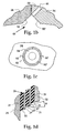
- Even more lock passageways may be included if desired ( See Fig. 1c).
- the at least one lock passage 44 should exhibit a diameter greater than about 0.03 inch. More preferably, the at least one lock passage 44 exhibits a diameter between about 0.03 inch and 0.09 inch, and most preferably, a diameter of about 0.06 inch.
- a plurality of lock passages 44, 44' interconnect between the compensator chamber 38 and an annular bubble trap 46 formed in a wall portion 48 of a highest one of said operating chambers 28, 30.
- the compensator chamber 38 should preferably be about half full of fluid 34 .
- a sight glass 55 is preferably mounted to a vertical wall portion 56 of said compensator chamber 38 enables viewing of the level of fluid 34 within the chamber 38 .
- a fill valve 58 provides means for pressurizing said gas-filled portion 40 thereby pressurizing the operating chambers 28, 30.
- an extension 56 projecting from a wall of the chamber 38 within the volume compensator 36 extends part way into the compensator chamber 38 .
- the extension 56 includes an opening 58 which is always covered by the fluid 34 regardless of the orientation of the mounting 20 .
- the fluid 34 within the fluid portion 42 covers the opening 58 . Since the opening is covered, no air can be reintroduced back into the operating chambers 28, 30 .
- the fluid 34 level in the chamber 38 must be greater than one-half full, and preferably about two-thirds full.
- a plurality of lock passages 44, 44' intersect with the opening 58.
- the extension 56 is formed on a plug 54' which threads into said outer member 24.
- any bubbles formed or within the operating chambers 28, 30 will migrate upward into the bubble trap 46 , then into the at least one lock passage 44 , through said fluid portion 42 , and into said gas-filled portion 40 .
- the gas over fluid design improves on prior art designs in that any air bubbles that are in the chambers 28, 30 can escape.
- Fig. 1d means are incorporated to prevent air trapping within the chambers 28, 30 if the fluid mounting 20 includes a flexible element 26 having laminated construction.
- laminated construction what is meant is any flexible element 26 which includes a least one rigid shim 27 and at least two elastomer layers 29 .
- Each of the at least two elastomer layers 29 include a sloping conical end portion 31 , one of which intersects with an end of the at least one rigid shim 27 and another which intersects with an end of said inner member 22 , thereby preventing air bubbles from becoming trapped.
- the sloping end portions 31 are angled at an angle theta O of at least 3 degrees from a horizontal plane.
- the at least one rigid shim 27 is tubular-shaped and includes an inner and outer diameter.
- the sloping end portion 31 preferably intersects the end of the at least one rigid shim 27 at its inner diameter.
- the mold would only locate the shim on this inner diameter. This provides support during bonding and allows the appropriate sloped contour.
Landscapes
- Engineering & Computer Science (AREA)
- General Engineering & Computer Science (AREA)
- Mechanical Engineering (AREA)
- Combined Devices Of Dampers And Springs (AREA)
Description
Claims (20)
- A fluid mounting (20), comprising:a) an inner member (22),b) an outer member (24),c) a flexible element (26) flexibly supporting said inner member (22) relative to said outer member (24),d) first (28) and second (30) operating chambers,e) a fluid passageway (32) interconnecting said first and second operating chambers (28, 30), characterised in that the fluid mounting (20) includes:f) a partitionless volume compensator (36) including a compensator chamber (38) separated into a gas-filled portion (40) and a fluid-filled portion (42), said gas-filled portion (42) overlying said fluid-filled portion (40), said chamber being devoid of any barrier separating said portions (40, 42),g) at least one lock passage (44) interconnecting said fluid-filled portion with one of said first and second operating chambers (28, 30),h) a fluid (34) within said first and second operating chambers (28, 30), said fluid passageway (32), said fluid-filled portion (42), and said at least one lock passage (44).
- A fluid mounting (20) of claim 1 wherein a bubble trap (46) formed in a wall portion (48) of one of said chambers (28, 30) focuses any bubbles present into said at least one lock passage (44).
- A fluid mounting (20) of claim 2 wherein said bubble trap (46) is an annular groove formed by cooperation between a chamfer (52) formed on a plug hole (50) interconnecting said compensator chamber (38) and one of said operating chambers (28, 30) and a chamfer (54') formed on a plug (54) received within said plug hole (50).
- A fluid mounting (20) of claim 1 wherein said at least one lock passage (44)comprises a plurality of lock passages (44, 44') to increase the speed at which bubbles enter said chamber (38).
- A fluid mounting (20) of claim 1 wherein said at least one lock passage (44) exhibits a diameter greater than about 0.03 inch.
- A fluid mounting (20) of claim 1 wherein said at least one lock passage (44) exhibits a diameter between about 0.03 inch and 0.09 inch.
- A fluid mounting (20) of claim 1 wherein said at least one lock passage (44) exhibits a diameter of about 0.06 inch.
- A fluid mounting (20) of claim 1 wherein said at least one lock passage (44) has a length and diameter selected such that flow of fluid (34) between said fluid-filled portion (42) and said chambers (28, 30) is substantially stopped at a predominant operating frequency of said mounting (20).
- A fluid mounting (20) of claim 1 wherein said compensator chamber is about half full of fluid (34).
- A fluid mounting (20) of claim 1 wherein said compensator chamber (38) includes a sight glass (55) mounted to a vertical wall portion (56) of said compensator chamber (38) to enable viewing of a level of said fluid (34) within said chamber (38).
- A fluid mounting (20) of claim 1 wherein a fill valve (58) provides means for pressurizing said gas-filled portion (40) thereby pressurizing said operating chambers (28, 30).
- A fluid mounting (20) of claim 1 wherein a plurality of lock passages (44, 44') interconnect between an annular bubble trap (46) formed in a wall portion (48) of a highest one of said operating chambers (28, 30) and said compensator chamber (38).
- A fluid mounting (20) of claim 1 including an extension (56) within said volume compensator (36) which extends part way into said compensator chamber (38), said extension (56) including an opening (58) which is always covered by said fluid (34) regardless of an orientation of said mounting (20).
- A fluid mounting (20) of claim 13 wherein said fluid (34) fills about two-thirds of said compensator chamber (38).
- A fluid mounting (20) of claim 13 wherein a plurality of lock passages (44, 44') intersect said opening (58).
- A fluid mounting (20) of claim 13 wherein said extension (56) is formed on a plug (54') which threads into said outer member (24).
- A fluid mounting (20) of claim 1 wherein any bubbles formed within said operating chambers (28, 30) will migrate upward into a bubble trap (46), then into said at least one lock passage (44), through said fluid portion (42) and into said gas-filled portion (40).
- A fluid mounting (20) of claim 1 wherein said flexible element includes laminated construction further including at least one rigid shim (27) and at least two elastomer layers (29), each of said at least two elastomer layers (29) including a sloping end portion (31), one of which intersects with an end of said at least one rigid shim (27) and another which intersects with an end of said inner member (22) thereby preventing air bubbles from becoming trapped.
- A fluid mounting (20) of claim 18 wherein sloping end portions (31) are angled at between 3 and 7 degrees from a horizontal plane.
- A fluid mounting (20) of claim 18 wherein said at least one rigid shim (27) is tubular-shaped and includes an inner diameter and an outer diameter, and said sloping end portion (31) intersects said end of said at least one rigid shim (27) at said inner diameter.
Applications Claiming Priority (3)
| Application Number | Priority Date | Filing Date | Title |
|---|---|---|---|
| US905368 | 1997-08-04 | ||
| US08/905,368 US6032936A (en) | 1997-08-04 | 1997-08-04 | Fluid mount including a partitionless compensator |
| PCT/US1998/016124 WO1999006733A1 (en) | 1997-08-04 | 1998-08-03 | Fluid mount including a partitionless compensator |
Publications (2)
| Publication Number | Publication Date |
|---|---|
| EP1000273A1 EP1000273A1 (en) | 2000-05-17 |
| EP1000273B1 true EP1000273B1 (en) | 2002-10-23 |
Family
ID=25420708
Family Applications (1)
| Application Number | Title | Priority Date | Filing Date |
|---|---|---|---|
| EP98938298A Expired - Lifetime EP1000273B1 (en) | 1997-08-04 | 1998-08-03 | Fluid mount including a partitionless compensator |
Country Status (5)
| Country | Link |
|---|---|
| US (2) | US6032936A (en) |
| EP (1) | EP1000273B1 (en) |
| CA (1) | CA2299454A1 (en) |
| DE (1) | DE69808925T2 (en) |
| WO (1) | WO1999006733A1 (en) |
Families Citing this family (24)
| Publication number | Priority date | Publication date | Assignee | Title |
|---|---|---|---|---|
| US6032936A (en) * | 1997-08-04 | 2000-03-07 | Lord Corporation | Fluid mount including a partitionless compensator |
| US6431530B1 (en) * | 2000-05-23 | 2002-08-13 | Bell Helicopter Textron, Inc. | Vertical liquid inertia vibration isolator |
| US6378851B1 (en) | 2000-10-25 | 2002-04-30 | Lord Corporation | Fluid and elastomer apparatus with discrete volume compensator and secondary compliance |
| US7084095B2 (en) * | 2001-04-04 | 2006-08-01 | Schlumberger Technology Corporation | Methods for controlling the rheological properties of viscoelastic surfactants based fluids |
| EP2182240B1 (en) * | 2002-09-24 | 2014-08-06 | Bell Helicopter Textron Inc. | A method of controlling the acoustic radiation of a ship |
| US6758466B2 (en) * | 2002-11-06 | 2004-07-06 | Lord Corporation | Fluid-elastomeric damper assembly including internal pumping mechanism |
| US7270321B2 (en) * | 2002-11-06 | 2007-09-18 | Lord Corporation | Fluid-elastomeric damper assembly including internal pumping mechanism |
| US7273447B2 (en) * | 2004-04-09 | 2007-09-25 | Otologics, Llc | Implantable hearing aid transducer retention apparatus |
| GB2418670B (en) | 2003-07-18 | 2007-06-27 | Avecia Inkjet Ltd | Phthalocyanines and their use in ink-jet printers |
| CN100567762C (en) * | 2005-02-18 | 2009-12-09 | 洛德公司 | Fluid elastomer damping assembly with internal pumping mechanism |
| US20060261530A1 (en) * | 2005-05-18 | 2006-11-23 | Bell Helicopter Textron Inc. | Preloaded one-way valve accumulator |
| EP2368066B1 (en) | 2008-12-18 | 2014-08-20 | Bell Helicopter Textron Inc. | Apparatus for improved vibration isolation |
| CN102405359B (en) | 2009-03-12 | 2015-02-11 | 贝尔直升机泰克斯特龙公司 | Method and apparatus for improved vibration isolation |
| EP2507531B1 (en) * | 2009-12-01 | 2014-04-16 | Bell Helicopter Textron Inc. | Apparatus for improved vibration isolation |
| US8840062B2 (en) * | 2011-04-11 | 2014-09-23 | Textron Innovations Inc. | Pylon mounting system with vibration isolation |
| US8882091B2 (en) | 2011-11-11 | 2014-11-11 | Textron Innovations Inc. | Vibration isolation system |
| US8672262B2 (en) * | 2012-01-10 | 2014-03-18 | Textron Innovations Inc. | Mechanically optimized liquid inertia vibration eliminator and aircraft pylon system |
| US9765641B2 (en) | 2012-08-23 | 2017-09-19 | Bell Helicopter Textron Inc. | System and method for vibration isolation |
| US9416842B2 (en) | 2013-03-27 | 2016-08-16 | Honeywell International Inc. | Isolators having damper-external thermal compensators and spacecraft isolation systems employing the same |
| US9587702B2 (en) | 2014-02-18 | 2017-03-07 | Honeywell International Inc. | Vibration isolator using externally pressurized sealing bellows and an external shaft |
| US9249856B1 (en) | 2014-03-18 | 2016-02-02 | Bell Helicopter Textron Inc. | Liquid inertia vibration mount |
| US9551393B2 (en) | 2014-04-23 | 2017-01-24 | Bell Helicopter Textron Inc. | Rotorcraft vibration isolation systems |
| JP6384986B2 (en) * | 2014-04-24 | 2018-09-05 | 株式会社ブリヂストン | Vibration isolator |
| US11131363B2 (en) * | 2017-10-16 | 2021-09-28 | Textron Innovations Inc. | Vibration attenuating fluid mount with partitioned compensator |
Family Cites Families (24)
| Publication number | Priority date | Publication date | Assignee | Title |
|---|---|---|---|---|
| GB1190943A (en) * | 1966-09-02 | 1970-05-06 | Peddinghaus Carl Ullrich Dr | Improvements relating to Hydraulic Shock Absorbers |
| NL7006737A (en) * | 1969-09-04 | 1971-03-08 | ||
| US3651902A (en) * | 1969-12-15 | 1972-03-28 | Peddinghaus Carl Ullrich Dr | Hydropneumatic shock absorber |
| JPS5830183B2 (en) * | 1975-08-07 | 1983-06-27 | トキコ株式会社 | Master cylinder reservoir tank |
| US4349184A (en) * | 1978-04-03 | 1982-09-14 | Barry Wright Corporation | Laminated bearings having elastomer layers of varying dimensions |
| US4236607A (en) * | 1979-02-26 | 1980-12-02 | Textron, Inc. | Vibration suppression system |
| DE3629860A1 (en) * | 1986-09-02 | 1988-03-10 | Metzeler Kautschuk | BEARING WITH HYDRAULIC DAMPING |
| DE3701264A1 (en) * | 1987-01-17 | 1988-07-28 | Opel Adam Ag | HYDRO BEARING |
| US4811919A (en) | 1987-08-06 | 1989-03-14 | Lord Corporation | Volume compensated fluid mount |
| US5219430A (en) * | 1990-03-13 | 1993-06-15 | Aerospatiale Societe Nationale Industrielle | Hydraulic damper and elastic-return strut comprising such a damper |
| US5197692A (en) | 1991-05-29 | 1993-03-30 | Lord Corporation | Adaptive fluid mount |
| US5127607A (en) | 1991-07-09 | 1992-07-07 | Lord Corporation | Fluid torque-restraint system with optimized fluid expansion |
| US5174552A (en) * | 1991-10-15 | 1992-12-29 | Lord Corporation | Fluid mount with active vibration control |
| US6022600A (en) * | 1992-04-24 | 2000-02-08 | Lord Corporation | High-temperature fluid mounting |
| US5374039A (en) | 1992-08-24 | 1994-12-20 | Lord Corporation | Fluid-and-elastomer support device |
| US5413320A (en) | 1993-06-17 | 1995-05-09 | Lord Corporation | Fluid mount for devices such as engines |
| US5435531A (en) * | 1993-08-18 | 1995-07-25 | Bell Helicopter Textron Inc. | Vibration isolation system |
| US5501434A (en) * | 1994-05-10 | 1996-03-26 | Lord Corporation | Hybrid fluid and elastomer damper |
| JP3734099B2 (en) * | 1994-06-06 | 2006-01-11 | マツダ株式会社 | Vibration damper |
| US5540549A (en) * | 1994-08-05 | 1996-07-30 | Lord Corporation | Fluid damping devices |
| US5788372A (en) * | 1996-05-10 | 1998-08-04 | Lord Corporation | Method and apparatus for reducing transient motion between an aircraft power member and structure during takeoff, landing and maneuvers |
| US6009983A (en) * | 1997-05-30 | 2000-01-04 | Bell Helicopter Textron, Inc. | Method and apparatus for improved vibration isolation |
| US6032936A (en) * | 1997-08-04 | 2000-03-07 | Lord Corporation | Fluid mount including a partitionless compensator |
| US6092795A (en) * | 1997-08-04 | 2000-07-25 | Lord Corporation | Fluid and elastomer damper |
-
1997
- 1997-08-04 US US08/905,368 patent/US6032936A/en not_active Expired - Fee Related
-
1998
- 1998-08-03 DE DE69808925T patent/DE69808925T2/en not_active Expired - Fee Related
- 1998-08-03 CA CA002299454A patent/CA2299454A1/en not_active Abandoned
- 1998-08-03 WO PCT/US1998/016124 patent/WO1999006733A1/en not_active Ceased
- 1998-08-03 EP EP98938298A patent/EP1000273B1/en not_active Expired - Lifetime
-
1999
- 1999-12-17 US US09/466,548 patent/US6217011B1/en not_active Expired - Lifetime
Also Published As
| Publication number | Publication date |
|---|---|
| WO1999006733A1 (en) | 1999-02-11 |
| DE69808925T2 (en) | 2003-06-18 |
| CA2299454A1 (en) | 1999-02-11 |
| EP1000273A1 (en) | 2000-05-17 |
| DE69808925D1 (en) | 2002-11-28 |
| US6217011B1 (en) | 2001-04-17 |
| US6032936A (en) | 2000-03-07 |
Similar Documents
| Publication | Publication Date | Title |
|---|---|---|
| US6032936A (en) | Fluid mount including a partitionless compensator | |
| EP0897490B1 (en) | Method for reducing transient motion between an aircraft power member and structure during takeoff, landing and maneuvers | |
| JP2977796B2 (en) | Fluid-filled elastic vibration damping device | |
| US4610421A (en) | Mounting construction for engine-transmission assembly | |
| KR100191104B1 (en) | Hydraulic damping bushing | |
| US20080048069A1 (en) | Uncoupled vibrion attenuation/isolation devices | |
| EP1000272A1 (en) | Fluid and elastomer apparatus | |
| US4971300A (en) | Motor mount having improved hydraulic damping | |
| US6749186B2 (en) | Hydraulic bushing with springs in parallel | |
| EP0623197B1 (en) | Elasto-hydraulic vibration isolator | |
| US20180290532A1 (en) | Hydraulic bearing and motor vehicle having such a hydraulic bearing | |
| JP2986586B2 (en) | Fluid-filled mount | |
| JPH08303522A (en) | Hydraulic damping type rubber supporter | |
| MX2007014455A (en) | Preloaded one-way valve accumulator. | |
| KR101938628B1 (en) | Engine mount with weight body | |
| US20030137087A1 (en) | Hydraulic bushing with springs in series | |
| JPS63266242A (en) | Fluid-sealed type mount device | |
| US20050077662A1 (en) | Intergrated channel plate and decoupler assembly for vibration isolator | |
| JPS58124841A (en) | Fluid filled engine mount unit | |
| KR100533078B1 (en) | Block type rubber mount enclosed fluid for vehicle | |
| KR200169305Y1 (en) | Power plant mount | |
| US6712345B2 (en) | Powertrain mount with high frequency plunger | |
| RU2174935C2 (en) | Device for securing flying vehicle engine | |
| JPH06193670A (en) | Fluid sealed type vibration isolator | |
| JP2001124132A (en) | Liquid sealed mount |
Legal Events
| Date | Code | Title | Description |
|---|---|---|---|
| PUAI | Public reference made under article 153(3) epc to a published international application that has entered the european phase |
Free format text: ORIGINAL CODE: 0009012 |
|
| 17P | Request for examination filed |
Effective date: 20000128 |
|
| AK | Designated contracting states |
Kind code of ref document: A1 Designated state(s): DE FR GB IT |
|
| 17Q | First examination report despatched |
Effective date: 20001124 |
|
| GRAG | Despatch of communication of intention to grant |
Free format text: ORIGINAL CODE: EPIDOS AGRA |
|
| GRAG | Despatch of communication of intention to grant |
Free format text: ORIGINAL CODE: EPIDOS AGRA |
|
| GRAH | Despatch of communication of intention to grant a patent |
Free format text: ORIGINAL CODE: EPIDOS IGRA |
|
| GRAH | Despatch of communication of intention to grant a patent |
Free format text: ORIGINAL CODE: EPIDOS IGRA |
|
| GRAA | (expected) grant |
Free format text: ORIGINAL CODE: 0009210 |
|
| AK | Designated contracting states |
Kind code of ref document: B1 Designated state(s): DE FR GB IT |
|
| REG | Reference to a national code |
Ref country code: GB Ref legal event code: FG4D |
|
| REF | Corresponds to: |
Ref document number: 69808925 Country of ref document: DE Date of ref document: 20021128 |
|
| ET | Fr: translation filed | ||
| PLBE | No opposition filed within time limit |
Free format text: ORIGINAL CODE: 0009261 |
|
| STAA | Information on the status of an ep patent application or granted ep patent |
Free format text: STATUS: NO OPPOSITION FILED WITHIN TIME LIMIT |
|
| 26N | No opposition filed |
Effective date: 20030724 |
|
| PGFP | Annual fee paid to national office [announced via postgrant information from national office to epo] |
Ref country code: GB Payment date: 20050727 Year of fee payment: 8 |
|
| PGFP | Annual fee paid to national office [announced via postgrant information from national office to epo] |
Ref country code: FR Payment date: 20050817 Year of fee payment: 8 |
|
| PGFP | Annual fee paid to national office [announced via postgrant information from national office to epo] |
Ref country code: DE Payment date: 20050930 Year of fee payment: 8 |
|
| PG25 | Lapsed in a contracting state [announced via postgrant information from national office to epo] |
Ref country code: DE Free format text: LAPSE BECAUSE OF NON-PAYMENT OF DUE FEES Effective date: 20070301 |
|
| GBPC | Gb: european patent ceased through non-payment of renewal fee |
Effective date: 20060803 |
|
| REG | Reference to a national code |
Ref country code: FR Ref legal event code: ST Effective date: 20070430 |
|
| PG25 | Lapsed in a contracting state [announced via postgrant information from national office to epo] |
Ref country code: GB Free format text: LAPSE BECAUSE OF NON-PAYMENT OF DUE FEES Effective date: 20060803 |
|
| PG25 | Lapsed in a contracting state [announced via postgrant information from national office to epo] |
Ref country code: FR Free format text: LAPSE BECAUSE OF NON-PAYMENT OF DUE FEES Effective date: 20060831 |
|
| PGFP | Annual fee paid to national office [announced via postgrant information from national office to epo] |
Ref country code: IT Payment date: 20120823 Year of fee payment: 15 |
|
| PG25 | Lapsed in a contracting state [announced via postgrant information from national office to epo] |
Ref country code: IT Free format text: LAPSE BECAUSE OF NON-PAYMENT OF DUE FEES Effective date: 20130803 |