EP0999923B1 - Marine connector - Google Patents
Marine connector Download PDFInfo
- Publication number
- EP0999923B1 EP0999923B1 EP98935955A EP98935955A EP0999923B1 EP 0999923 B1 EP0999923 B1 EP 0999923B1 EP 98935955 A EP98935955 A EP 98935955A EP 98935955 A EP98935955 A EP 98935955A EP 0999923 B1 EP0999923 B1 EP 0999923B1
- Authority
- EP
- European Patent Office
- Prior art keywords
- toggle
- receiver
- toggle nose
- nose
- pins
- Prior art date
- Legal status (The legal status is an assumption and is not a legal conclusion. Google has not performed a legal analysis and makes no representation as to the accuracy of the status listed.)
- Expired - Lifetime
Links
- 230000007246 mechanism Effects 0.000 claims abstract description 19
- 230000033001 locomotion Effects 0.000 claims abstract description 18
- 230000000295 complement effect Effects 0.000 claims description 4
- 238000003032 molecular docking Methods 0.000 abstract description 23
- 230000013011 mating Effects 0.000 abstract description 2
- 210000001331 nose Anatomy 0.000 description 87
- 239000000523 sample Substances 0.000 description 5
- 238000000926 separation method Methods 0.000 description 5
- 238000005452 bending Methods 0.000 description 4
- 238000011068 loading method Methods 0.000 description 3
- 238000001228 spectrum Methods 0.000 description 3
- 230000004044 response Effects 0.000 description 2
- 230000009471 action Effects 0.000 description 1
- 238000004873 anchoring Methods 0.000 description 1
- 230000009286 beneficial effect Effects 0.000 description 1
- 230000008602 contraction Effects 0.000 description 1
- 230000001419 dependent effect Effects 0.000 description 1
- 238000006073 displacement reaction Methods 0.000 description 1
- 229930195733 hydrocarbon Natural products 0.000 description 1
- 150000002430 hydrocarbons Chemical class 0.000 description 1
- 238000012986 modification Methods 0.000 description 1
- 230000004048 modification Effects 0.000 description 1
- 238000007665 sagging Methods 0.000 description 1
- 238000004513 sizing Methods 0.000 description 1
- 230000001360 synchronised effect Effects 0.000 description 1
- XLYOFNOQVPJJNP-UHFFFAOYSA-N water Substances O XLYOFNOQVPJJNP-UHFFFAOYSA-N 0.000 description 1
Images




Classifications
-
- B—PERFORMING OPERATIONS; TRANSPORTING
- B63—SHIPS OR OTHER WATERBORNE VESSELS; RELATED EQUIPMENT
- B63B—SHIPS OR OTHER WATERBORNE VESSELS; EQUIPMENT FOR SHIPPING
- B63B21/00—Tying-up; Shifting, towing, or pushing equipment; Anchoring
-
- B—PERFORMING OPERATIONS; TRANSPORTING
- B63—SHIPS OR OTHER WATERBORNE VESSELS; RELATED EQUIPMENT
- B63B—SHIPS OR OTHER WATERBORNE VESSELS; EQUIPMENT FOR SHIPPING
- B63B35/00—Vessels or similar floating structures specially adapted for specific purposes and not otherwise provided for
- B63B35/34—Pontoons
-
- B—PERFORMING OPERATIONS; TRANSPORTING
- B63—SHIPS OR OTHER WATERBORNE VESSELS; RELATED EQUIPMENT
- B63B—SHIPS OR OTHER WATERBORNE VESSELS; EQUIPMENT FOR SHIPPING
- B63B35/00—Vessels or similar floating structures specially adapted for specific purposes and not otherwise provided for
- B63B35/34—Pontoons
- B63B35/38—Rigidly-interconnected pontoons
-
- B—PERFORMING OPERATIONS; TRANSPORTING
- B63—SHIPS OR OTHER WATERBORNE VESSELS; RELATED EQUIPMENT
- B63B—SHIPS OR OTHER WATERBORNE VESSELS; EQUIPMENT FOR SHIPPING
- B63B35/00—Vessels or similar floating structures specially adapted for specific purposes and not otherwise provided for
- B63B35/66—Tugs
- B63B35/665—Floating propeller units, i.e. a motor and propeller unit mounted in a floating box
-
- B—PERFORMING OPERATIONS; TRANSPORTING
- B63—SHIPS OR OTHER WATERBORNE VESSELS; RELATED EQUIPMENT
- B63B—SHIPS OR OTHER WATERBORNE VESSELS; EQUIPMENT FOR SHIPPING
- B63B35/00—Vessels or similar floating structures specially adapted for specific purposes and not otherwise provided for
- B63B35/44—Floating buildings, stores, drilling platforms, or workshops, e.g. carrying water-oil separating devices
- B63B2035/442—Spar-type semi-submersible structures, i.e. shaped as single slender, e.g. substantially cylindrical or trussed vertical bodies
-
- Y—GENERAL TAGGING OF NEW TECHNOLOGICAL DEVELOPMENTS; GENERAL TAGGING OF CROSS-SECTIONAL TECHNOLOGIES SPANNING OVER SEVERAL SECTIONS OF THE IPC; TECHNICAL SUBJECTS COVERED BY FORMER USPC CROSS-REFERENCE ART COLLECTIONS [XRACs] AND DIGESTS
- Y10—TECHNICAL SUBJECTS COVERED BY FORMER USPC
- Y10T—TECHNICAL SUBJECTS COVERED BY FORMER US CLASSIFICATION
- Y10T403/00—Joints and connections
- Y10T403/59—Manually releaseable latch type
Definitions
- the invention is generally related to offshore vessels and more particularly to the connection and disconnection of large floating objects in the offshore environment during higher sea states.
- Means for connecting two or more floating objects can be designed to restrict relative motion of the two objects in one, or more, of the six degrees of freedom.
- the rotational degrees of freedom are yaw, roll, and pitch. Resisting relative yaw of the two objects produces bending in the horizontal plane, resisting relative roll produces torsion, and resisting relative pitch produces hogging and sagging.
- the moment produced by resisting each rotational degree of freedom must be developed by a couple produced by a pair of connectors. A couple produces its greatest resisting moment when its moment arm is greatest. Therefore, the connectors producing each couple should be spaced as far apart as possible.
- the translational degrees of freedom are sway, surge, and heave. Resisting relative sway of the two objects produces transverse loads on the connectors, resisting relative surge produces longitudinal load on the connectors, and resisting relative heave produces vertical load on the connectors.
- the couple forces required to resist the rotational degrees of freedom are much greater than the forces required to resist the translational degrees of freedom.
- the magnitude of the couple required to resist relative pitch is so great that the marine connector must be designed to release pitch.
- Connectors designed to resist relative roll and yaw must be placed as far outboard to port and starboard as possible, but also must be designed to release pitch.
- the roll and yaw connectors may also be used to resist the relative translational degrees of freedom.
- Fig. 1 shows two floating objects 10 rigidly connected at the four corners, as indicated by numeral 12. Rigidly connected in this usage means that the connection is not compliant. Although the connectors are ideally located at the extremities, the couple required to prevent relative pitch will be too great for practical design.
- torsion has a ratio between its first and second modes of about two.
- first torsional mode were twenty seconds
- second torsional mode would be about ten seconds.
- Bending in the horizontal plane has a slightly better ratio of about two point seven seconds.
- the first horizontal plane bending mode were twenty-seven seconds
- the second mode would be ten seconds.
- a ratio between the first and second modes of about six is required. For instance, if a structure were contrived with a twenty-seven second first mode in torsion, its second torsional mode would be about four point five seconds. At this ratio, the first and second torsional modes fall above and below, respectively, the periods of the high energy spectrum waves.
- the connectors and the structure, supporting the connectors must be designed for the dynamically amplified loadings induced by the torsional and horizontal plane bending modes. The higher loadings will also make the fatigue problems worse.
- An optional design would be to substitute compliant connectors for the rigid connectors, thereby altering the dynamic response of the connected units favorably.
- a major consideration in this option is that the design load for the connector is equal to the maximum capacity of the compliant element, provided the compliant element is designed so that it never reaches the end of its stroke.
- Another problem is that the two floating objects to be connected must be brought into close enough alignment for the connectors to engage.
- the alignment operation is called docking and must be facilitated with a docking system. If the relative motions for which the docking and connection systems are designed are exceeded then the operation will have to wait for the lower motions that will come when the seas moderate.
- the connectors and the structure supporting the connectors must be designed to resist the forces that are induced by the impinging sea state. If the connected objects encounter a large storm that continues to worsen, or some other emergency occurs, the objects may have to be disconnected while the connectors are resisting large loads. Therefore, the connectors must be designed with the capability to disconnect under load. Once disconnected, the floating objects will quickly develop the relative motions of two independently floating objects. Therefore, the connection and docking systems must facilitate quick separation of the two objects to prevent impact between features on the two objects.
- the connectors must be synchronized so they all connect or disconnect simultaneously. Otherwise, damage will occur.
- US Patent US 3,920,219 considered to be the closest prior art, provides a connecting structure for an ocean-going push barge combination.
- Three connecting pins arranged at the bow, starboard and port sides of a pusher boat facilitate the connection of the pusher boat and barge.
- the pins are extendable and retractable such that they engage in corresponding sockets at the stern of the barge so as to rigidly connect the pusher boat and barge together.
- the pusher boat enters a deep notch in the stern of the barge such that the pins and sockets can align to rigidly join the pusher boat and barge together to eliminate independent movement of each vessel. Therefore, when connected the two vessels form a single seagoing unit.
- the present invention seeks to address the above needs.
- the present invention provides a marine connector comprising a toggle nose attachable to a first floating object, said toggle nose being orientable in a horizontal plane across a longitudinal axis of the first floating object; a toggle nose receiver attachable to a second floating object, said toggle nose receiver being shaped to receive said toggle nose and having sockets provided thereon, with the shape of said receiver preventing vertical movement of said toggle nose within said receiver while allowing relative pitch between said toggle nose and receiver; and two opposed pins received in said toggle nose so as to be movable between a first retracted position and a second extended position in contact with the sockets in said toggle nose receiver, said opposed pins being movable in a horizontal plane across a longitudinal axis of the floating objects.
- a marine connector facilitates docking of large floating objects during a sea state that produces significant relative motion between the two objects.
- a toggle nose is mounted on one floating object and a mating device, a toggle nose receiver, is mounted on the second floating object.
- the toggle nose contains a toggle mechanism that extends and retracts two opposed transverse pins having conical ends.
- the toggle nose receiver is provided with corresponding conical sockets to receive the ends of the pins. Bevels on the toggle nose and receiver permit loose tolerance in yaw during the docking operation. Where the toggle nose and receivers are located both port and starboard, a central docking probe may be provided for additional guidance during the docking operation.
- the marine connector of the invention is generally comprised of a toggle nose 22 and a toggle nose receiver 24.
- Fig. 2A, B generally and schematically illustrate the concept of the invention where two floating objects 10 are rigidly connected by connectors 14 with transverse colinear pins 16.
- the transverse pins 16 release relative pitch, but resist relative yaw and roll, which requires that the pair of connectors 14 be located as far to port and starboard as possible.
- Toggle nose 22 seen in Fig. 5A,B and 6A,B, is comprised of a pipe 26, transverse pins 28, toggle mechanism 30 attached to the pins 28 for moving the pins 28 between a first retracted position and a second extended position, and bearings 33 and 35.
- Pipe 26 is spaced apart from and rigidly attached to the floating object 10 by means of plates 29 and bearings 33 and 35. Internal plates 31 provide support to the assembly. Bearings 33, 35 slidably receive and provide support for transverse pins 28.
- a winged bearing 33 is rigidly attached at each end of pipe 26. As seen in Fig. 5A, winged bearing 33 is shaped to provide a bevel angle relative to floating object 10 as indicated at 27.
- a bearing 35 is positioned internally in pipe 26 on each side of toggle mechanism 30.
- the pipe provides a curved leading edge to toggle nose 22. The bevel and curved leading edge eliminate the need for perfect alignment with the toggle nose receiver 24 during docking operations. As seen in Fig.
- slide blocks 37 fit on the top and bottom ends of central pin 41 of toggle mechanism 30 where toggle joint arms 34 are pivotally attached to each other.
- U-shaped channels 39 are rigidly mounted in pipe 26 and form slides 32 that slidably receive blocks 37 for forward and reverse toggle motion, indicated by the arrows in Fig. 5A and 6A, and also restrict side-to-side motion of the entire toggle mechanism 30 when loads are placed along the longitudinal axis of the pins 28.
- a stop 38 is provided in frame 26 directly in line with yoke 36 and is sized to a length such that the yoke 36 is allowed to move the toggle mechanism 30 only slightly beyond its center point as seen in Fig. 6A. The purpose of this will be explained below.
- Pins 28 are attached on the ends of the arms 34 of the toggle mechanism and are slidably received in bearings 35 and bearings 33 on either end of the pipe 26 so as to be movable between a first retracted position (Fig. 5A) and a second extended position (Fig. 6A).
- the ends 42 of pins 28 are illustrated as being conical in the drawings. However, since a number of surfaces of revolution are suitable, the term conical should be taken as referring to any number of surfaces of revolution.
- the conical ends 42 of the transverse pins 28 serve several functions.
- the toggle nose When the transverse pins are extended and seated in the sockets, the toggle nose is locked into its receiver. When any force acts to separate the nose and its receiver, the conical pin ends are pushed inward, which forces the toggle against its stop. So the conical pin end provides a passive, reliable lock.
- an actuator (not shown) must push or pull the toggle mechanism off the stop and past center. Once the toggle mechanism is past center, it has no significant load carrying capacity. When the separation of the two floating objects reacts the conical socket against the conical pin ends, the pin ends are driven inward, which will collapse the toggle mechanism, if it has been previously pushed off its stop past center. So the conical pin ends provide an automatic disconnect feature.
- toggle mechanism 30 The operational principle of toggle mechanism 30 is well known, with two arms 34 that are hinged together for pivoting motion and are each connected at their opposite ends to one end of transverse pins 34 such that movement of arms 34 by yoke 36 causes corresponding translational movement of transverse pins 28.
- Toggle nose receiver 24 is formed from a combined housing and support frame 44 (Fig. 4, 7, and 8) that is formed so as to be integral with and rigidly attached to a second floating object 10.
- the sides of housing/support frame 44 are beveled at an angle that is complementary to the bevel of the toggle nose 22.
- the upper, lower, and rear edges are curved in a complementary shape to the leading edge curve of toggle nose 22.
- Sockets 46, one at each side, have a complementary shape and size to pin ends 42 so as to receive pins 28 when in their second extended position.
- Fig. 7 illustrates toggle nose 22 received in toggle nose receiver 24 with pins 28 in their first retracted position.
- FIG. 8 illustrates toggle nose 22 received in toggle nose receiver 24 with pins 28 in their second extended position and engaged in sockets 46. It can be seen in Fig. 8 that when pins 28 are fully engaged with sockets 46, that toggle nose 22 and toggle nose receiver 24 are sized such that there is no contact between the pipe 26 and housings/frame 44. The only point of contact is between the ends 42 of pins 28 and the surfaces of sockets 46 of housing/frame 44. Another feature of the relative sizing of toggle nose 22 and toggle nose receiver 24, and positioning of pins 28 and sockets 46 is that, during the docking operation, the leading edge of toggle nose 22 may be placed into full contact with the rearmost interior of toggle nose receiver 24 and the toggle mechanism 30 may still be operated to engage pins 28 in sockets 46. The conical shape of pin ends 42 and sockets 46 allow pins 28 to engage sockets 46 and force toggle nose 22 and toggle nose receiver 24 into the fully connected and locked, non-contact position shown in Fig. 8.
- any force tending to separate the toggle nose 22 from the toggle nose receiver 24 must be resisted in shear by the pins 28.
- the pins 28 will act against the sockets 46 in a direction normal to the axis of the pins 28 with a force equal to the shear load in the pins 28.
- the shear load on the pin 28 will induce an axial load in the pin 28 equal to the shear load, if the pin ends are forty-five degree cones.
- the pins 28 will push axially against the sockets 46 with a load equal to the shear load in the pins 28.
- the sockets 46 will deliver the axial pin load to the housing frame 44, which in turn will deliver the load to the tension bars 23 shown in Fig. 14.
- the tension bars 23 extend from the housing frame 44 on one side of the toggle nose receiver 24 to the housing frame 44 on the other side.
- the tension bars react the load in one side of the toggle nose receiver, against the load in the other side. For instance, suppose a longitudinal load of fifty thousand tons acts to separate a toggle nose 22 from its toggle nose receiver 24. A shear load of twenty-five thousand tons in each pin 28 would resist the longitudinal load. The shear loads on each pin end 42 would induce an axial load of twenty-five thousand tons in the pins 28 and toggle members 34. The twenty-five thousand ton pin load would react against the sockets 46 and would be transferred via the housing frames 44 to the tension bars 23. Top and bottom tension bars would each develop twelve thousand five hundred tons and react one side of the toggle nose receiver against the other.
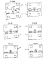
- FIG. 9A-F illustrate such a situation and also show the docking sequence and yaw tolerance provided by the invention.
- the corresponding ends of floating objects 10 are respectively provided with a docking probe 48 and docking receptacle 50.
- floating objects 10 are vertically aligned by ballasting to obtain the correct trim and draft.
- Positioning means such as anchoring systems or dynamic positioning systems are used to transversely align floating objects 10 and then force the ends toward each other, seen in Fig. 9A.
- Fig. 9C illustrates the yaw tolerance provided by the invention for engaging toggle nose 22 in toggle nose receiver 24 once docking probe 48 has been engaged with receptacle 50.
- Fig. 9D illustrates the yaw tolerance provided when both toggle noses 22 and toggle nose receivers 24 are engaged.
- Fig. 9E illustrates both toggle noses 22 and toggle nose receivers 24 fully seated.
- Fig. 9F illustrates the transverse pins 28 extended and the docking and connection operations completed.
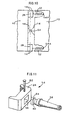
- Fig. 10 schematically illustrates the use of a compliant element 52 in conjunction with the invention.
- a marine connector 14 as described above is provided with a universal connection, schematically illustrated and indicated by numeral 54.
- the universal joint 54 prevents relative translation of the floating objects 10 in sway, surge, and heave, but permits relative rotation of the floating objects 10 in yaw, roll, and pitch.
- the colinear transverse pins 28 on the port and starboard connectors 14 and the universal connection permit relative pitch of the floating objects 10.
- the compliant elements 52 offer resistance to extension and contraction. Therefore, the compliant elements 52 offer considerable resistance to relative yaw of the connected objects 10 and some resistance to relative roll.
- the compliant element 52 is attached at a first end to connector 14 and at a second to the floating object 10.
- the connection between the port and starboard compliant elements 52 and floating object 10 must be made using a universal joint, schematically indicated at 54A.
- Fig. 11 illustrates the central universal joint 54.
- Toggle nose receiver 24 is provided with a bore 56.
- a longitudinal shaft 58 has a first end 60 sized to be received in bore 56.
- Vertical pin 62 is inserted in a bore in toggle nose receiver and through bore 64.
- the longitudinal shaft 58 cantilevers the toggle nose receiver 24 from the floating object 10 and permits rotation about the vertical axis.
- the remainder of longitudinal shaft 58 is rotatably attached to floating object 10, which allows the whole assembly (receiver 24 and shaft 58) to rotate about the shaft centerline.
- the transverse opposed pins in the toggle nose permit rotation about the transverse axis. Therefore, a universal joint is formed because rotation is permitted about three orthogonal axes.
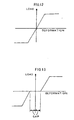
- the compliant elements produce the axial load versus deformation relation of the shape shown in Fig. 12.
- the gaps shown in the axial load versus deformation relation of Fig. 13 are also advantageous.
- the gaps could be fixed or variable depending on requirements.
- the invention provides a number of advantages.
- the toggle nose and toggle nose receiver are shaped in a way that facilitates docking, i.e., forcing the toggle nose into the toggle nose receiver reduces the relative motion between the floating objects and controls the location well enough to make the connection.
- the transverse pins are locked in the engaged position by a passive system; the stop is not dependent on hydraulic seals or any other hydraulic or mechanical system.
- the conical pin ends and the conical socket make it possible to connect while the floating objects are moving relative to each other.
- the transverse pins have a short distance to move from fully retracted to fully extended. This means that connection and disconnection can be done quickly.
- the toggle nose and toggle nose receiver are shaped in a way that facilitates separation in higher sea state.
- the floating objects must move only a short distance, the radius of the toggle nose, in order to be fully separated.
- Fig. 7 and 14 illustrate these advantages: It can be seen that the two floating objects only have to move a total distance equal to the radius of the toggle nose 22 to be separated. Thus, the separation can be done quickly and the shape of the toggle nose 22 and its receiver 24 will permit the nose to slide off the receiver without damage.
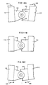
- Fig. 14A-C illustrate the large tolerance for relative pitch of the floating objects 10 when the toggle nose 22 is seated in its receiver 24.
- Fig. 14A illustrates the nose and receiver bowed up, as indicated by arrows 66.
- Fig. 14B illustrates the nose and receiver at zero pitch.
- Fig. 14C illustrates the nose and receiver bowed down, as indicated by arrows 68.
- the toggle mechanism To disconnect, the toggle mechanism must be pushed off the stop past center. Once pushed that far (a few inches at most) the toggle mechanism can be released by the action of the two floating objects separating.
- the toggle nose and toggle nose receiver are a fully integrated docking and connection system.
- the shape of the nose and receiver facilitates docking and separation and supports the toggle mechanism and its opposed transverse pins in the ideal position for making the connection.
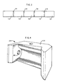
- Fig. 3 illustrates one use of the invention where a number of floating objects 10 are connected end-to-end. This type of arrangement will serve the purpose of a mobile floating airfield or base.
- Fig. 15 illustrates another use of the invention where a transport barge 70 and offshore structure 72 used to drill for and produce hydrocarbons are connected using the marine connector 14 of the invention. This connection enables a superstructure 74 to be skidded from the transport barge 70 onto the offshore structure 72 without the need for heavy lift crane barges or floatover systems as currently used.
Landscapes
- Chemical & Material Sciences (AREA)
- Engineering & Computer Science (AREA)
- Combustion & Propulsion (AREA)
- Mechanical Engineering (AREA)
- Ocean & Marine Engineering (AREA)
- Details Of Connecting Devices For Male And Female Coupling (AREA)
- Earth Drilling (AREA)
- Bridges Or Land Bridges (AREA)
- Heat Treatment Of Steel (AREA)
- Connector Housings Or Holding Contact Members (AREA)
Abstract
Description
- The invention is generally related to offshore vessels and more particularly to the connection and disconnection of large floating objects in the offshore environment during higher sea states.
- Different types of operations in the offshore environment present the need for the connection and disconnection of large floating objects. However, accomplishing such operations presents unique and extreme engineering and operational needs.
- Two floating objects in unprotected water will have significant relative motion in six degrees of freedom in the higher sea states. Means for connecting two or more floating objects can be designed to restrict relative motion of the two objects in one, or more, of the six degrees of freedom. The rotational degrees of freedom are yaw, roll, and pitch. Resisting relative yaw of the two objects produces bending in the horizontal plane, resisting relative roll produces torsion, and resisting relative pitch produces hogging and sagging. The moment produced by resisting each rotational degree of freedom must be developed by a couple produced by a pair of connectors. A couple produces its greatest resisting moment when its moment arm is greatest. Therefore, the connectors producing each couple should be spaced as far apart as possible. The translational degrees of freedom are sway, surge, and heave. Resisting relative sway of the two objects produces transverse loads on the connectors, resisting relative surge produces longitudinal load on the connectors, and resisting relative heave produces vertical load on the connectors.
- The couple forces required to resist the rotational degrees of freedom are much greater than the forces required to resist the translational degrees of freedom. For large objects, the magnitude of the couple required to resist relative pitch is so great that the marine connector must be designed to release pitch. Connectors designed to resist relative roll and yaw must be placed as far outboard to port and starboard as possible, but also must be designed to release pitch. The roll and yaw connectors may also be used to resist the relative translational degrees of freedom.
- Fig. 1 shows two
floating objects 10 rigidly connected at the four corners, as indicated bynumeral 12. Rigidly connected in this usage means that the connection is not compliant. Although the connectors are ideally located at the extremities, the couple required to prevent relative pitch will be too great for practical design. - The impinging sea state applies most of the loadings to the connected objects. Therefore, the loads applied to the connected objects and the loads induced in the connectors are primarily dynamic. In some applications, the dynamic response of the connected objects can be a problem. For instance, where
several objects 10 are rigidly connected bow to stern, as shown in Fig. 3, torsion has a ratio between its first and second modes of about two. Thus, if the first torsional mode were twenty seconds, the second torsional mode would be about ten seconds. Bending in the horizontal plane has a slightly better ratio of about two point seven seconds. Thus, if the first horizontal plane bending mode were twenty-seven seconds, the second mode would be ten seconds. These ratios are too low to avoid resonance with waves in the high energy spectrum. To adequately straddle the periods of the high energy spectrum waves, a ratio between the first and second modes of about six is required. For instance, if a structure were contrived with a twenty-seven second first mode in torsion, its second torsional mode would be about four point five seconds. At this ratio, the first and second torsional modes fall above and below, respectively, the periods of the high energy spectrum waves. - If the objects are rigidly connected in the example given above, then the connectors and the structure, supporting the connectors must be designed for the dynamically amplified loadings induced by the torsional and horizontal plane bending modes. The higher loadings will also make the fatigue problems worse. An optional design would be to substitute compliant connectors for the rigid connectors, thereby altering the dynamic response of the connected units favorably. A major consideration in this option is that the design load for the connector is equal to the maximum capacity of the compliant element, provided the compliant element is designed so that it never reaches the end of its stroke.
- Another problem is that the two floating objects to be connected must be brought into close enough alignment for the connectors to engage. The alignment operation is called docking and must be facilitated with a docking system. If the relative motions for which the docking and connection systems are designed are exceeded then the operation will have to wait for the lower motions that will come when the seas moderate. The connectors and the structure supporting the connectors must be designed to resist the forces that are induced by the impinging sea state. If the connected objects encounter a large storm that continues to worsen, or some other emergency occurs, the objects may have to be disconnected while the connectors are resisting large loads. Therefore, the connectors must be designed with the capability to disconnect under load. Once disconnected, the floating objects will quickly develop the relative motions of two independently floating objects. Therefore, the connection and docking systems must facilitate quick separation of the two objects to prevent impact between features on the two objects.
- Also, where more than one connector is used between the floating objects, the connectors must be synchronized so they all connect or disconnect simultaneously. Otherwise, damage will occur.
- An example follows of the loads that are encountered when connecting floating objects. For five floating objects, each being one thousand feet long and five hundred feet wide, the magnitude of the design load for rigidly mounted connectors, port and starboard, varies from twenty thousand metric tons to about one hundred thousand metric tons. The magnitude of the design load for compliant connectors, port and starboard, ranges from five thousand metric tons to ten thousand metric tons. The connectors must be capable of releasing while these types of loads are active. The inventors are not aware of connectors that meet these requirements.
- US Patent US 3,920,219 considered to be the closest prior art, provides a connecting structure for an ocean-going push barge combination. Three connecting pins arranged at the bow, starboard and port sides of a pusher boat facilitate the connection of the pusher boat and barge. The pins are extendable and retractable such that they engage in corresponding sockets at the stern of the barge so as to rigidly connect the pusher boat and barge together. The pusher boat enters a deep notch in the stern of the barge such that the pins and sockets can align to rigidly join the pusher boat and barge together to eliminate independent movement of each vessel. Therefore, when connected the two vessels form a single seagoing unit.
- The present invention seeks to address the above needs.
- Accordingly, the present invention provides a marine connector comprising a toggle nose attachable to a first floating object, said toggle nose being orientable in a horizontal plane across a longitudinal axis of the first floating object; a toggle nose receiver attachable to a second floating object, said toggle nose receiver being shaped to receive said toggle nose and having sockets provided thereon, with the shape of said receiver preventing vertical movement of said toggle nose within said receiver while allowing relative pitch between said toggle nose and receiver; and two opposed pins received in said toggle nose so as to be movable between a first retracted position and a second extended position in contact with the sockets in said toggle nose receiver, said opposed pins being movable in a horizontal plane across a longitudinal axis of the floating objects.
- A marine connector according to an embodiment of the invention facilitates docking of large floating objects during a sea state that produces significant relative motion between the two objects. A toggle nose is mounted on one floating object and a mating device, a toggle nose receiver, is mounted on the second floating object. The toggle nose contains a toggle mechanism that extends and retracts two opposed transverse pins having conical ends. The toggle nose receiver is provided with corresponding conical sockets to receive the ends of the pins. Bevels on the toggle nose and receiver permit loose tolerance in yaw during the docking operation. Where the toggle nose and receivers are located both port and starboard, a central docking probe may be provided for additional guidance during the docking operation.
- For a further understanding of the nature of the present invention reference should be had to the following description, taken in conjunction with the accompanying drawings in which like parts are given like reference numerals, and wherein:
- Fig. 1 illustrates a prior art rigid connection.
- Fig. 2A and 2B respectively are plan and elevation views illustrating a rigid connection that releases relative pitch.
- Fig. 3 is a plan view of several floating objects connected together using the connectors of Fig. 2.
- Fig. 4 is a perspective view of the toggle nose receiver of the invention.
- Fig. 5A is a plan cutaway view of the toggle nose of the invention with the transverse opposed pins in their retracted position.
- Fig. 5B is a view taken along lines B-B of Fig. 5A.
- Fig. 6A is a plan cutaway view of the toggle nose of the invention with the transverse opposed pins in their extended position.
- Fig. 6B is a view taken along lines B-B of Fig. 6A.
- Fig. 7 is a horizontal section through the center line of the toggle nose seated in its receiver with the transverse pins retracted.
- Fig. 8 is a horizontal section through the center line of the toggle nose seated in its receiver with the transverse pins extended.
- Fig. 9A-F illustrate a plan view of the docking sequence between two floating objects using the invention.
- Fig. 10 is a schematic illustration of the use of a compliant element in conjunction with the invention.
- Fig. 11 illustrates a universal joint of the invention.
- Fig. 12 and 13 illustrate load and deformation characteristics of compliant elements in connectors.
- Fig. 14A-F are vertical sections through a toggle nose seated in a toggle nose receiver.
- Fig. 15 illustrates one use of the invention.
-
- Referring to Fig. 4 and 5, the marine connector of the invention is generally comprised of a
toggle nose 22 and atoggle nose receiver 24. Fig. 2A, B generally and schematically illustrate the concept of the invention where two floatingobjects 10 are rigidly connected byconnectors 14 with transverse colinear pins 16. The transverse pins 16 release relative pitch, but resist relative yaw and roll, which requires that the pair ofconnectors 14 be located as far to port and starboard as possible. -
Toggle nose 22, seen in Fig. 5A,B and 6A,B, is comprised of apipe 26,transverse pins 28,toggle mechanism 30 attached to thepins 28 for moving thepins 28 between a first retracted position and a second extended position, andbearings -
Pipe 26 is spaced apart from and rigidly attached to the floatingobject 10 by means ofplates 29 andbearings Internal plates 31 provide support to the assembly.Bearings transverse pins 28. Awinged bearing 33 is rigidly attached at each end ofpipe 26. As seen in Fig. 5A,winged bearing 33 is shaped to provide a bevel angle relative to floatingobject 10 as indicated at 27. Abearing 35 is positioned internally inpipe 26 on each side oftoggle mechanism 30. The pipe provides a curved leading edge to togglenose 22. The bevel and curved leading edge eliminate the need for perfect alignment with thetoggle nose receiver 24 during docking operations. As seen in Fig. 6B, slide blocks 37 fit on the top and bottom ends ofcentral pin 41 oftoggle mechanism 30 where togglejoint arms 34 are pivotally attached to each other.U-shaped channels 39 are rigidly mounted inpipe 26 and form slides 32 that slidably receiveblocks 37 for forward and reverse toggle motion, indicated by the arrows in Fig. 5A and 6A, and also restrict side-to-side motion of theentire toggle mechanism 30 when loads are placed along the longitudinal axis of thepins 28. Astop 38 is provided inframe 26 directly in line withyoke 36 and is sized to a length such that theyoke 36 is allowed to move thetoggle mechanism 30 only slightly beyond its center point as seen in Fig. 6A. The purpose of this will be explained below. -
Pins 28 are attached on the ends of thearms 34 of the toggle mechanism and are slidably received inbearings 35 andbearings 33 on either end of thepipe 26 so as to be movable between a first retracted position (Fig. 5A) and a second extended position (Fig. 6A). The ends 42 ofpins 28 are illustrated as being conical in the drawings. However, since a number of surfaces of revolution are suitable, the term conical should be taken as referring to any number of surfaces of revolution. - The conical ends 42 of the
transverse pins 28 serve several functions. - When the
toggle nose 22 is docked in thetoggle nose receiver 24, there will still be relative motion between the floating objects 10, which will cause relative motion between the toggle nose and receiver. The diameters of the conical pin end and the conical socket are made large enough that the pin end will always engage the socket when the pins are extended, even with the maximum relative displacement of pin end and socket present. So the conical pin ends provide reliable connection between the floating objects, while these objects are moving relative to each other. - When the transverse pins are extended and seated in the sockets, the toggle nose is locked into its receiver. When any force acts to separate the nose and its receiver, the conical pin ends are pushed inward, which forces the toggle against its stop. So the conical pin end provides a passive, reliable lock.
- To disconnect the toggle nose from the toggle nose receiver, an actuator (not shown) must push or pull the toggle mechanism off the stop and past center. Once the toggle mechanism is past center, it has no significant load carrying capacity. When the separation of the two floating objects reacts the conical socket against the conical pin ends, the pin ends are driven inward, which will collapse the toggle mechanism, if it has been previously pushed off its stop past center. So the conical pin ends provide an automatic disconnect feature.
- The operational principle of
toggle mechanism 30 is well known, with twoarms 34 that are hinged together for pivoting motion and are each connected at their opposite ends to one end oftransverse pins 34 such that movement ofarms 34 byyoke 36 causes corresponding translational movement oftransverse pins 28. -
Toggle nose receiver 24 is formed from a combined housing and support frame 44 (Fig. 4, 7, and 8) that is formed so as to be integral with and rigidly attached to a second floatingobject 10. The sides of housing/support frame 44 are beveled at an angle that is complementary to the bevel of thetoggle nose 22. The upper, lower, and rear edges are curved in a complementary shape to the leading edge curve oftoggle nose 22.Sockets 46, one at each side, have a complementary shape and size to pin ends 42 so as to receivepins 28 when in their second extended position. Fig. 7 illustratestoggle nose 22 received intoggle nose receiver 24 withpins 28 in their first retracted position. Fig. 8 illustratestoggle nose 22 received intoggle nose receiver 24 withpins 28 in their second extended position and engaged insockets 46. It can be seen in Fig. 8 that when pins 28 are fully engaged withsockets 46, thattoggle nose 22 and togglenose receiver 24 are sized such that there is no contact between thepipe 26 and housings/frame 44. The only point of contact is between theends 42 ofpins 28 and the surfaces ofsockets 46 of housing/frame 44. Another feature of the relative sizing oftoggle nose 22 and togglenose receiver 24, and positioning ofpins 28 andsockets 46 is that, during the docking operation, the leading edge oftoggle nose 22 may be placed into full contact with the rearmost interior oftoggle nose receiver 24 and thetoggle mechanism 30 may still be operated to engagepins 28 insockets 46. The conical shape of pin ends 42 andsockets 46 allowpins 28 to engagesockets 46 andforce toggle nose 22 and togglenose receiver 24 into the fully connected and locked, non-contact position shown in Fig. 8. - Once the conical pin ends 42 are seated in the
sockets 46, any force tending to separate thetoggle nose 22 from thetoggle nose receiver 24 must be resisted in shear by thepins 28. Thepins 28 will act against thesockets 46 in a direction normal to the axis of thepins 28 with a force equal to the shear load in thepins 28. In addition, the shear load on thepin 28 will induce an axial load in thepin 28 equal to the shear load, if the pin ends are forty-five degree cones. Thepins 28 will push axially against thesockets 46 with a load equal to the shear load in thepins 28. Thesockets 46 will deliver the axial pin load to thehousing frame 44, which in turn will deliver the load to the tension bars 23 shown in Fig. 14. The tension bars 23 extend from thehousing frame 44 on one side of thetoggle nose receiver 24 to thehousing frame 44 on the other side. Thus, the tension bars react the load in one side of the toggle nose receiver, against the load in the other side. For instance, suppose a longitudinal load of fifty thousand tons acts to separate atoggle nose 22 from itstoggle nose receiver 24. A shear load of twenty-five thousand tons in eachpin 28 would resist the longitudinal load. The shear loads on each pin end 42 would induce an axial load of twenty-five thousand tons in thepins 28 andtoggle members 34. The twenty-five thousand ton pin load would react against thesockets 46 and would be transferred via the housing frames 44 to the tension bars 23. Top and bottom tension bars would each develop twelve thousand five hundred tons and react one side of the toggle nose receiver against the other. - In situations where a
toggle nose 22 and togglenose receiver 24 are used on both the port and starboard extremities of the ends being used to connect the floating objects, the use of a docking probe and receptacle may be beneficial during the docking operation. Fig. 9A-F illustrate such a situation and also show the docking sequence and yaw tolerance provided by the invention. The corresponding ends of floatingobjects 10 are respectively provided with adocking probe 48 anddocking receptacle 50. - In operation, floating
objects 10 are vertically aligned by ballasting to obtain the correct trim and draft. Positioning means such as anchoring systems or dynamic positioning systems are used to transversely align floatingobjects 10 and then force the ends toward each other, seen in Fig. 9A. When dockingprobe 48 engages receptacle 50 (Fig.9B), floatingobjects 10 are forced into tight enough transverse alignment to start the engagement oftoggle noses 22 and togglenose receivers 24. Fig. 9C illustrates the yaw tolerance provided by the invention for engagingtoggle nose 22 intoggle nose receiver 24 oncedocking probe 48 has been engaged withreceptacle 50. Fig. 9D illustrates the yaw tolerance provided when bothtoggle noses 22 and togglenose receivers 24 are engaged. Fig. 9E illustrates both togglenoses 22 and togglenose receivers 24 fully seated. Fig. 9F illustrates thetransverse pins 28 extended and the docking and connection operations completed. - Fig. 10 schematically illustrates the use of a
compliant element 52 in conjunction with the invention. In this embodiment, amarine connector 14 as described above is provided with a universal connection, schematically illustrated and indicated bynumeral 54. Theuniversal joint 54 prevents relative translation of the floating objects 10 in sway, surge, and heave, but permits relative rotation of the floating objects 10 in yaw, roll, and pitch. The colineartransverse pins 28 on the port andstarboard connectors 14 and the universal connection permit relative pitch of the floating objects 10. Thecompliant elements 52 offer resistance to extension and contraction. Therefore, thecompliant elements 52 offer considerable resistance to relative yaw of theconnected objects 10 and some resistance to relative roll. Thecompliant element 52 is attached at a first end toconnector 14 and at a second to the floatingobject 10. The connection between the port and starboardcompliant elements 52 and floatingobject 10 must be made using a universal joint, schematically indicated at 54A. - Fig. 11 illustrates the central
universal joint 54.Toggle nose receiver 24 is provided with abore 56. Alongitudinal shaft 58 has afirst end 60 sized to be received inbore 56.Vertical pin 62 is inserted in a bore in toggle nose receiver and throughbore 64. Thus, thelongitudinal shaft 58 cantilevers thetoggle nose receiver 24 from the floatingobject 10 and permits rotation about the vertical axis. The remainder oflongitudinal shaft 58 is rotatably attached to floatingobject 10, which allows the whole assembly (receiver 24 and shaft 58) to rotate about the shaft centerline. The transverse opposed pins in the toggle nose permit rotation about the transverse axis. Therefore, a universal joint is formed because rotation is permitted about three orthogonal axes. - The compliant elements produce the axial load versus deformation relation of the shape shown in Fig. 12. There may be circumstances where the gaps shown in the axial load versus deformation relation of Fig. 13 are also advantageous. The gaps could be fixed or variable depending on requirements.
- The invention provides a number of advantages.
- The toggle nose and toggle nose receiver are shaped in a way that facilitates docking, i.e., forcing the toggle nose into the toggle nose receiver reduces the relative motion between the floating objects and controls the location well enough to make the connection.
- When the toggle mechanism is driven past center against the stop, the transverse pins are locked in the engaged position by a passive system; the stop is not dependent on hydraulic seals or any other hydraulic or mechanical system.
- The conical pin ends and the conical socket make it possible to connect while the floating objects are moving relative to each other. The transverse pins have a short distance to move from fully retracted to fully extended. This means that connection and disconnection can be done quickly. The toggle nose and toggle nose receiver are shaped in a way that facilitates separation in higher sea state. The floating objects must move only a short distance, the radius of the toggle nose, in order to be fully separated. Fig. 7 and 14 illustrate these advantages: It can be seen that the two floating objects only have to move a total distance equal to the radius of the
toggle nose 22 to be separated. Thus, the separation can be done quickly and the shape of thetoggle nose 22 and itsreceiver 24 will permit the nose to slide off the receiver without damage. - Fig. 14A-C illustrate the large tolerance for relative pitch of the floating
objects 10 when thetoggle nose 22 is seated in itsreceiver 24. Fig. 14A illustrates the nose and receiver bowed up, as indicated byarrows 66. Fig. 14B illustrates the nose and receiver at zero pitch. Fig. 14C illustrates the nose and receiver bowed down, as indicated byarrows 68. - To disconnect, the toggle mechanism must be pushed off the stop past center. Once pushed that far (a few inches at most) the toggle mechanism can be released by the action of the two floating objects separating.
- The toggle nose and toggle nose receiver are a fully integrated docking and connection system. The shape of the nose and receiver facilitates docking and separation and supports the toggle mechanism and its opposed transverse pins in the ideal position for making the connection.
- Fig. 3 illustrates one use of the invention where a number of floating
objects 10 are connected end-to-end. This type of arrangement will serve the purpose of a mobile floating airfield or base. Fig. 15 illustrates another use of the invention where atransport barge 70 andoffshore structure 72 used to drill for and produce hydrocarbons are connected using themarine connector 14 of the invention. This connection enables asuperstructure 74 to be skidded from thetransport barge 70 onto theoffshore structure 72 without the need for heavy lift crane barges or floatover systems as currently used. - Because many varying and differing embodiments may be made within the scope of the inventive concept herein taught and because many modifications may be made in the embodiment herein detailed in accordance with the descriptive requirement of the law, it is to be understood that the details herein are to be interpreted as illustrative and not in a limiting sense.
Claims (6)
- A marine connector comprising:a toggle nose (22) attachable to a first floating object (10), said toggle nose (22) being orientable in a horizontal plane across a longitudinal axis of the first floating object (10);a toggle nose receiver (24) attachable to a second floating object (10), said toggle nose receiver (24) being shaped to receive said toggle nose (22) and having sockets provided thereon, with the shape of said receiver (24) preventing vertical movement of said toggle nose (22) within said receiver (24) while allowing relative pitch between said toggle nose (22) and receiver (24); andtwo opposed pins (28) received in said toggle nose (22) so as to be movable between a first retracted position and a second extended position in contact with the sockets in said toggle nose receiver (24), said opposed pins (28) being movable in a horizontal plane across a longitudinal axis of the floating objects (10).
- The marine connector of claim 1, wherein said toggle nose (22) and toggle nose receiver (24) are provided with complementary beveled and curved shapes.
- The marine connector of claim 1, further comprising a toggle mechanism (30) for moving said transverse opposed pins (28) between said first and second positions.
- The marine connector of claim 3, further comprising means (38) for stopping said toggle mechanism (30) at a position slightly beyond centre when said transverse opposed pins (28) are in said second extended position.
- The marine connector of claim 1, wherein said toggle nose receiver (24) is attachable to the second floating object (10) by means of a compliant element (52).
- The marine connector of claim 1, wherein said transverse pins (28) and sockets in said toggle nose receiver (24) form the only point of contact between said toggle nose (22) and said toggle nose receiver (24) when said transverse pins (28) are in their second extended position and received in the sockets in said toggle nose receiver (24).
Applications Claiming Priority (3)
| Application Number | Priority Date | Filing Date | Title |
|---|---|---|---|
| US903776 | 1997-07-31 | ||
| US08/903,776 US5988932A (en) | 1997-07-31 | 1997-07-31 | Marine connector |
| PCT/US1998/015258 WO1999006188A1 (en) | 1997-07-31 | 1998-07-20 | Marine connector |
Publications (3)
| Publication Number | Publication Date |
|---|---|
| EP0999923A1 EP0999923A1 (en) | 2000-05-17 |
| EP0999923A4 EP0999923A4 (en) | 2002-09-18 |
| EP0999923B1 true EP0999923B1 (en) | 2004-10-13 |
Family
ID=25418050
Family Applications (1)
| Application Number | Title | Priority Date | Filing Date |
|---|---|---|---|
| EP98935955A Expired - Lifetime EP0999923B1 (en) | 1997-07-31 | 1998-07-20 | Marine connector |
Country Status (12)
| Country | Link |
|---|---|
| US (1) | US5988932A (en) |
| EP (1) | EP0999923B1 (en) |
| CN (1) | CN1139515C (en) |
| AU (1) | AU740785B2 (en) |
| BR (1) | BR9811491A (en) |
| DE (1) | DE69827008D1 (en) |
| ID (1) | ID24883A (en) |
| MY (1) | MY122689A (en) |
| NO (1) | NO321010B1 (en) |
| OA (1) | OA11314A (en) |
| TR (1) | TR200000294T2 (en) |
| WO (1) | WO1999006188A1 (en) |
Families Citing this family (12)
| Publication number | Priority date | Publication date | Assignee | Title |
|---|---|---|---|---|
| US6210076B1 (en) * | 1997-07-31 | 2001-04-03 | Mcdermott Technology, Inc. | Offshore deck installation |
| US6470820B1 (en) * | 2000-01-28 | 2002-10-29 | Cdi Corporation | Interlocking system, apparatus and method for connecting modules |
| US7527450B2 (en) * | 2005-02-04 | 2009-05-05 | Rri Holdings, Inc. | Selectably operable field mateable pin assembly |
| US20090038088A1 (en) * | 2007-06-05 | 2009-02-12 | Richard Steven Adler | Rapid deployment floating bridges |
| CN102862656A (en) * | 2012-10-22 | 2013-01-09 | 东莞市科旺网络能源有限公司 | A modular water platform |
| RU2545128C1 (en) * | 2014-01-14 | 2015-03-27 | Александр Александрович Новиков | Floating island |
| CN105882927B (en) * | 2014-04-30 | 2018-04-10 | 王海龙 | Combined type aircraft carrier |
| JP6732187B2 (en) * | 2016-03-02 | 2020-07-29 | 国立研究開発法人 海上・港湾・航空技術研究所 | Semi-sub type floating body and connecting method of semi-sub type floating body |
| NL2017388B1 (en) * | 2016-08-30 | 2018-03-08 | Hallcon B V | SYSTEM FOR TRANSFERRING PERSONS AND / OR CARGO WITH A SHUTTLE |
| KR102433992B1 (en) * | 2021-06-09 | 2022-08-18 | 박덕치 | Hydraulic connector for the offshore landing platform module |
| CN114212198B (en) * | 2021-12-15 | 2022-10-11 | 上海大学 | Anti-shock automatic docking mechanism and method for surface unmanned platform |
| CN114688934B (en) * | 2022-06-02 | 2022-07-29 | 中海油能源发展股份有限公司采油服务分公司 | Three-center alignment detection method and device for bilge position of ship |
Family Cites Families (8)
| Publication number | Priority date | Publication date | Assignee | Title |
|---|---|---|---|---|
| US3844215A (en) * | 1960-04-13 | 1974-10-29 | Us Army | Mine fuze |
| JPS5437397B2 (en) * | 1972-03-06 | 1979-11-14 | ||
| US3799101A (en) * | 1973-06-29 | 1974-03-26 | Johnson Rubber Co | Bearing for articulated barge or the like |
| US3910219A (en) * | 1973-10-05 | 1975-10-07 | Aoki Construction | Connecting structure for ocean-going push-barge |
| JPS5736200B2 (en) * | 1974-04-15 | 1982-08-02 | ||
| US4119051A (en) * | 1977-09-29 | 1978-10-10 | Chicago Bridge & Iron Company | Rigid mooring arm quick disconnect |
| JPS6141678Y2 (en) * | 1981-04-10 | 1986-11-27 | ||
| US5439310A (en) * | 1993-05-25 | 1995-08-08 | The United States Of America As Represented By United States National Aeronautics And Space Administration | Connector systems for structures |
-
1997
- 1997-07-31 US US08/903,776 patent/US5988932A/en not_active Expired - Lifetime
-
1998
- 1998-07-20 TR TR2000/00294T patent/TR200000294T2/en unknown
- 1998-07-20 DE DE69827008T patent/DE69827008D1/en not_active Expired - Lifetime
- 1998-07-20 BR BR9811491-3A patent/BR9811491A/en not_active IP Right Cessation
- 1998-07-20 ID IDW20000188A patent/ID24883A/en unknown
- 1998-07-20 WO PCT/US1998/015258 patent/WO1999006188A1/en not_active Ceased
- 1998-07-20 CN CNB98808984XA patent/CN1139515C/en not_active Expired - Fee Related
- 1998-07-20 EP EP98935955A patent/EP0999923B1/en not_active Expired - Lifetime
- 1998-07-20 AU AU85096/98A patent/AU740785B2/en not_active Ceased
-
2000
- 2000-01-26 MY MYPI20000275A patent/MY122689A/en unknown
- 2000-01-28 OA OA1200000022A patent/OA11314A/en unknown
- 2000-01-28 NO NO20000458A patent/NO321010B1/en not_active IP Right Cessation
Also Published As
| Publication number | Publication date |
|---|---|
| ID24883A (en) | 2000-08-31 |
| OA11314A (en) | 2003-10-27 |
| WO1999006188A1 (en) | 1999-02-11 |
| NO20000458L (en) | 2000-03-22 |
| NO321010B1 (en) | 2006-02-27 |
| CN1269743A (en) | 2000-10-11 |
| CN1139515C (en) | 2004-02-25 |
| AU740785B2 (en) | 2001-11-15 |
| AU8509698A (en) | 1999-02-22 |
| MY122689A (en) | 2006-04-29 |
| DE69827008D1 (en) | 2004-11-18 |
| EP0999923A4 (en) | 2002-09-18 |
| NO20000458D0 (en) | 2000-01-28 |
| EP0999923A1 (en) | 2000-05-17 |
| BR9811491A (en) | 2000-09-19 |
| TR200000294T2 (en) | 2001-07-23 |
| US5988932A (en) | 1999-11-23 |
Similar Documents
| Publication | Publication Date | Title |
|---|---|---|
| US5988932A (en) | Marine connector | |
| US4114556A (en) | Rigid mooring arm hook-up system | |
| EP3368404B1 (en) | Disconnectable tower yoke assembly and method of using same | |
| CN101035708B (en) | Offshore vessel mooring and riser inboarding system | |
| AU2003261408B2 (en) | Duplex yoke mooring-system | |
| US4193368A (en) | Offshore mooring system for vessel or ship | |
| EP2310257B1 (en) | Apparatus for coupling a pushboat to a barge | |
| US11305843B2 (en) | System for quick release of mooring and loading and unloading lines between a loading and unloading station at sea and a vessel | |
| CN113316539A (en) | Yoke plate assembly for mooring device and mooring device comprising same | |
| US6561739B1 (en) | Load transporting modular platform system | |
| US20190382083A1 (en) | Device for coupling two boats | |
| US6470820B1 (en) | Interlocking system, apparatus and method for connecting modules | |
| CN112793710B (en) | Three-degree-of-freedom slide connector for connecting transfer barge and semi-submersible platform | |
| US4335670A (en) | Flexible side connector for floating and elevated platforms | |
| US4441448A (en) | Controlled mooring | |
| US3756183A (en) | Apparatus for articulated towboat barge combination | |
| US20240425148A1 (en) | Articulated mechanical connectors and processes for using same | |
| US3994140A (en) | Stinger coupling | |
| KR20190059650A (en) | Intergrated tug-barge system | |
| US20240326954A1 (en) | Swivel connectors for u-joints and processes for using same | |
| WO2000066422A1 (en) | Method and device for coupling a vessel to another vessel or to a structure | |
| WO2022245298A2 (en) | A coupling system for connecting floating modules for nearshore development | |
| GB2145377A (en) | Improvements in or relating to the push towing of barges |
Legal Events
| Date | Code | Title | Description |
|---|---|---|---|
| PUAI | Public reference made under article 153(3) epc to a published international application that has entered the european phase |
Free format text: ORIGINAL CODE: 0009012 |
|
| 17P | Request for examination filed |
Effective date: 20000204 |
|
| AK | Designated contracting states |
Kind code of ref document: A1 Designated state(s): BE DE DK ES FI FR GB GR IE IT MC NL PT SE |
|
| A4 | Supplementary search report drawn up and despatched |
Effective date: 20020806 |
|
| AK | Designated contracting states |
Kind code of ref document: A4 Designated state(s): BE DE DK ES FI FR GB GR IE IT MC NL PT SE |
|
| RIC1 | Information provided on ipc code assigned before grant |
Free format text: 7B 25G 3/18 A, 7B 63B 35/38 B |
|
| 17Q | First examination report despatched |
Effective date: 20021108 |
|
| GRAP | Despatch of communication of intention to grant a patent |
Free format text: ORIGINAL CODE: EPIDOSNIGR1 |
|
| GRAS | Grant fee paid |
Free format text: ORIGINAL CODE: EPIDOSNIGR3 |
|
| GRAA | (expected) grant |
Free format text: ORIGINAL CODE: 0009210 |
|
| RAP1 | Party data changed (applicant data changed or rights of an application transferred) |
Owner name: J. RAY MCDERMOTT, S.A. |
|
| AK | Designated contracting states |
Kind code of ref document: B1 Designated state(s): BE DE DK ES FI FR GB GR IE IT MC NL PT SE |
|
| PG25 | Lapsed in a contracting state [announced via postgrant information from national office to epo] |
Ref country code: FI Free format text: LAPSE BECAUSE OF FAILURE TO SUBMIT A TRANSLATION OF THE DESCRIPTION OR TO PAY THE FEE WITHIN THE PRESCRIBED TIME-LIMIT Effective date: 20041013 |
|
| REG | Reference to a national code |
Ref country code: GB Ref legal event code: FG4D |
|
| REG | Reference to a national code |
Ref country code: IE Ref legal event code: FG4D |
|
| REF | Corresponds to: |
Ref document number: 69827008 Country of ref document: DE Date of ref document: 20041118 Kind code of ref document: P |
|
| PG25 | Lapsed in a contracting state [announced via postgrant information from national office to epo] |
Ref country code: SE Free format text: LAPSE BECAUSE OF FAILURE TO SUBMIT A TRANSLATION OF THE DESCRIPTION OR TO PAY THE FEE WITHIN THE PRESCRIBED TIME-LIMIT Effective date: 20050113 Ref country code: GR Free format text: LAPSE BECAUSE OF FAILURE TO SUBMIT A TRANSLATION OF THE DESCRIPTION OR TO PAY THE FEE WITHIN THE PRESCRIBED TIME-LIMIT Effective date: 20050113 Ref country code: DK Free format text: LAPSE BECAUSE OF FAILURE TO SUBMIT A TRANSLATION OF THE DESCRIPTION OR TO PAY THE FEE WITHIN THE PRESCRIBED TIME-LIMIT Effective date: 20050113 |
|
| PG25 | Lapsed in a contracting state [announced via postgrant information from national office to epo] |
Ref country code: DE Free format text: LAPSE BECAUSE OF FAILURE TO SUBMIT A TRANSLATION OF THE DESCRIPTION OR TO PAY THE FEE WITHIN THE PRESCRIBED TIME-LIMIT Effective date: 20050114 |
|
| PG25 | Lapsed in a contracting state [announced via postgrant information from national office to epo] |
Ref country code: ES Free format text: LAPSE BECAUSE OF FAILURE TO SUBMIT A TRANSLATION OF THE DESCRIPTION OR TO PAY THE FEE WITHIN THE PRESCRIBED TIME-LIMIT Effective date: 20050124 |
|
| ET | Fr: translation filed | ||
| PG25 | Lapsed in a contracting state [announced via postgrant information from national office to epo] |
Ref country code: MC Free format text: LAPSE BECAUSE OF NON-PAYMENT OF DUE FEES Effective date: 20050731 |
|
| PLBE | No opposition filed within time limit |
Free format text: ORIGINAL CODE: 0009261 |
|
| STAA | Information on the status of an ep patent application or granted ep patent |
Free format text: STATUS: NO OPPOSITION FILED WITHIN TIME LIMIT |
|
| 26N | No opposition filed |
Effective date: 20050714 |
|
| PG25 | Lapsed in a contracting state [announced via postgrant information from national office to epo] |
Ref country code: PT Free format text: LAPSE BECAUSE OF NON-PAYMENT OF DUE FEES Effective date: 20050313 |
|
| PGFP | Annual fee paid to national office [announced via postgrant information from national office to epo] |
Ref country code: IE Payment date: 20140728 Year of fee payment: 17 Ref country code: NL Payment date: 20140726 Year of fee payment: 17 |
|
| PGFP | Annual fee paid to national office [announced via postgrant information from national office to epo] |
Ref country code: GB Payment date: 20140729 Year of fee payment: 17 Ref country code: FR Payment date: 20140717 Year of fee payment: 17 |
|
| PGFP | Annual fee paid to national office [announced via postgrant information from national office to epo] |
Ref country code: IT Payment date: 20140724 Year of fee payment: 17 |
|
| PGFP | Annual fee paid to national office [announced via postgrant information from national office to epo] |
Ref country code: BE Payment date: 20140730 Year of fee payment: 17 |
|
| GBPC | Gb: european patent ceased through non-payment of renewal fee |
Effective date: 20150720 |
|
| REG | Reference to a national code |
Ref country code: NL Ref legal event code: MM Effective date: 20150801 |
|
| REG | Reference to a national code |
Ref country code: IE Ref legal event code: MM4A |
|
| PG25 | Lapsed in a contracting state [announced via postgrant information from national office to epo] |
Ref country code: GB Free format text: LAPSE BECAUSE OF NON-PAYMENT OF DUE FEES Effective date: 20150720 Ref country code: IT Free format text: LAPSE BECAUSE OF NON-PAYMENT OF DUE FEES Effective date: 20150720 |
|
| REG | Reference to a national code |
Ref country code: FR Ref legal event code: ST Effective date: 20160331 |
|
| PG25 | Lapsed in a contracting state [announced via postgrant information from national office to epo] |
Ref country code: NL Free format text: LAPSE BECAUSE OF NON-PAYMENT OF DUE FEES Effective date: 20150801 Ref country code: FR Free format text: LAPSE BECAUSE OF NON-PAYMENT OF DUE FEES Effective date: 20150731 |
|
| PG25 | Lapsed in a contracting state [announced via postgrant information from national office to epo] |
Ref country code: IE Free format text: LAPSE BECAUSE OF NON-PAYMENT OF DUE FEES Effective date: 20150720 |
|
| PG25 | Lapsed in a contracting state [announced via postgrant information from national office to epo] |
Ref country code: BE Free format text: LAPSE BECAUSE OF NON-PAYMENT OF DUE FEES Effective date: 20150731 |