EP0999916B1 - Key duplication apparatus and method - Google Patents
Key duplication apparatus and method Download PDFInfo
- Publication number
- EP0999916B1 EP0999916B1 EP98938080A EP98938080A EP0999916B1 EP 0999916 B1 EP0999916 B1 EP 0999916B1 EP 98938080 A EP98938080 A EP 98938080A EP 98938080 A EP98938080 A EP 98938080A EP 0999916 B1 EP0999916 B1 EP 0999916B1
- Authority
- EP
- European Patent Office
- Prior art keywords
- key
- keyway
- keycode
- control signal
- preform
- Prior art date
- Legal status (The legal status is an assumption and is not a legal conclusion. Google has not performed a legal analysis and makes no representation as to the accuracy of the status listed.)
- Expired - Lifetime
Links
- 238000000034 method Methods 0.000 title claims abstract description 71
- 238000005259 measurement Methods 0.000 claims abstract description 49
- 238000003754 machining Methods 0.000 claims description 20
- 230000004044 response Effects 0.000 claims description 12
- 238000004519 manufacturing process Methods 0.000 claims description 2
- 230000008569 process Effects 0.000 abstract description 13
- 238000005520 cutting process Methods 0.000 description 53
- 238000013519 translation Methods 0.000 description 41
- 230000014616 translation Effects 0.000 description 33
- 238000004891 communication Methods 0.000 description 9
- 238000000926 separation method Methods 0.000 description 9
- 230000003287 optical effect Effects 0.000 description 8
- 239000000463 material Substances 0.000 description 4
- 238000012986 modification Methods 0.000 description 4
- 230000004048 modification Effects 0.000 description 4
- 238000013459 approach Methods 0.000 description 3
- 230000008859 change Effects 0.000 description 3
- 238000012423 maintenance Methods 0.000 description 3
- 239000000700 radioactive tracer Substances 0.000 description 3
- 230000008901 benefit Effects 0.000 description 2
- 238000012544 monitoring process Methods 0.000 description 2
- 230000002159 abnormal effect Effects 0.000 description 1
- 230000015572 biosynthetic process Effects 0.000 description 1
- 230000000903 blocking effect Effects 0.000 description 1
- 239000002131 composite material Substances 0.000 description 1
- 230000001010 compromised effect Effects 0.000 description 1
- 238000001514 detection method Methods 0.000 description 1
- 238000011161 development Methods 0.000 description 1
- 238000010586 diagram Methods 0.000 description 1
- 238000006073 displacement reaction Methods 0.000 description 1
- 230000006870 function Effects 0.000 description 1
- 238000009499 grossing Methods 0.000 description 1
- 230000003993 interaction Effects 0.000 description 1
- 239000007769 metal material Substances 0.000 description 1
- 238000003909 pattern recognition Methods 0.000 description 1
- 230000002250 progressing effect Effects 0.000 description 1
- 230000008439 repair process Effects 0.000 description 1
- 238000012552 review Methods 0.000 description 1
- 238000001228 spectrum Methods 0.000 description 1
- 230000007704 transition Effects 0.000 description 1
Images









Classifications
-
- B—PERFORMING OPERATIONS; TRANSPORTING
- B23—MACHINE TOOLS; METAL-WORKING NOT OTHERWISE PROVIDED FOR
- B23C—MILLING
- B23C3/00—Milling particular work; Special milling operations; Machines therefor
- B23C3/28—Grooving workpieces
- B23C3/35—Milling grooves in keys
-
- E—FIXED CONSTRUCTIONS
- E05—LOCKS; KEYS; WINDOW OR DOOR FITTINGS; SAFES
- E05B—LOCKS; ACCESSORIES THEREFOR; HANDCUFFS
- E05B19/00—Keys; Accessories therefor
- E05B19/0011—Key decoders
-
- B—PERFORMING OPERATIONS; TRANSPORTING
- B23—MACHINE TOOLS; METAL-WORKING NOT OTHERWISE PROVIDED FOR
- B23C—MILLING
- B23C2235/00—Details of milling keys
- B23C2235/28—Key blanks
-
- B—PERFORMING OPERATIONS; TRANSPORTING
- B23—MACHINE TOOLS; METAL-WORKING NOT OTHERWISE PROVIDED FOR
- B23C—MILLING
- B23C2235/00—Details of milling keys
- B23C2235/32—Measurement systems
-
- Y—GENERAL TAGGING OF NEW TECHNOLOGICAL DEVELOPMENTS; GENERAL TAGGING OF CROSS-SECTIONAL TECHNOLOGIES SPANNING OVER SEVERAL SECTIONS OF THE IPC; TECHNICAL SUBJECTS COVERED BY FORMER USPC CROSS-REFERENCE ART COLLECTIONS [XRACs] AND DIGESTS
- Y10—TECHNICAL SUBJECTS COVERED BY FORMER USPC
- Y10T—TECHNICAL SUBJECTS COVERED BY FORMER US CLASSIFICATION
- Y10T409/00—Gear cutting, milling, or planing
- Y10T409/30—Milling
- Y10T409/30084—Milling with regulation of operation by templet, card, or other replaceable information supply
- Y10T409/300896—Milling with regulation of operation by templet, card, or other replaceable information supply with sensing of numerical information and regulation without mechanical connection between sensing means and regulated means [i.e., numerical control]
-
- Y—GENERAL TAGGING OF NEW TECHNOLOGICAL DEVELOPMENTS; GENERAL TAGGING OF CROSS-SECTIONAL TECHNOLOGIES SPANNING OVER SEVERAL SECTIONS OF THE IPC; TECHNICAL SUBJECTS COVERED BY FORMER USPC CROSS-REFERENCE ART COLLECTIONS [XRACs] AND DIGESTS
- Y10—TECHNICAL SUBJECTS COVERED BY FORMER USPC
- Y10T—TECHNICAL SUBJECTS COVERED BY FORMER US CLASSIFICATION
- Y10T409/00—Gear cutting, milling, or planing
- Y10T409/30—Milling
- Y10T409/30084—Milling with regulation of operation by templet, card, or other replaceable information supply
- Y10T409/300952—Milling with regulation of operation by templet, card, or other replaceable information supply to cut lock key
-
- Y—GENERAL TAGGING OF NEW TECHNOLOGICAL DEVELOPMENTS; GENERAL TAGGING OF CROSS-SECTIONAL TECHNOLOGIES SPANNING OVER SEVERAL SECTIONS OF THE IPC; TECHNICAL SUBJECTS COVERED BY FORMER USPC CROSS-REFERENCE ART COLLECTIONS [XRACs] AND DIGESTS
- Y10—TECHNICAL SUBJECTS COVERED BY FORMER USPC
- Y10T—TECHNICAL SUBJECTS COVERED BY FORMER US CLASSIFICATION
- Y10T409/00—Gear cutting, milling, or planing
- Y10T409/30—Milling
- Y10T409/30084—Milling with regulation of operation by templet, card, or other replaceable information supply
- Y10T409/300952—Milling with regulation of operation by templet, card, or other replaceable information supply to cut lock key
- Y10T409/301064—Complete cycle
-
- Y—GENERAL TAGGING OF NEW TECHNOLOGICAL DEVELOPMENTS; GENERAL TAGGING OF CROSS-SECTIONAL TECHNOLOGIES SPANNING OVER SEVERAL SECTIONS OF THE IPC; TECHNICAL SUBJECTS COVERED BY FORMER USPC CROSS-REFERENCE ART COLLECTIONS [XRACs] AND DIGESTS
- Y10—TECHNICAL SUBJECTS COVERED BY FORMER USPC
- Y10T—TECHNICAL SUBJECTS COVERED BY FORMER US CLASSIFICATION
- Y10T409/00—Gear cutting, milling, or planing
- Y10T409/30—Milling
- Y10T409/30084—Milling with regulation of operation by templet, card, or other replaceable information supply
- Y10T409/301176—Reproducing means
- Y10T409/301624—Duplicating means
- Y10T409/30168—Duplicating means with means for operation without manual intervention
- Y10T409/301792—Duplicating means with means for operation without manual intervention including means to sense optical or magnetic image
-
- Y—GENERAL TAGGING OF NEW TECHNOLOGICAL DEVELOPMENTS; GENERAL TAGGING OF CROSS-SECTIONAL TECHNOLOGIES SPANNING OVER SEVERAL SECTIONS OF THE IPC; TECHNICAL SUBJECTS COVERED BY FORMER USPC CROSS-REFERENCE ART COLLECTIONS [XRACs] AND DIGESTS
- Y10—TECHNICAL SUBJECTS COVERED BY FORMER USPC
- Y10T—TECHNICAL SUBJECTS COVERED BY FORMER US CLASSIFICATION
- Y10T409/00—Gear cutting, milling, or planing
- Y10T409/30—Milling
- Y10T409/30084—Milling with regulation of operation by templet, card, or other replaceable information supply
- Y10T409/301176—Reproducing means
- Y10T409/301624—Duplicating means
- Y10T409/30168—Duplicating means with means for operation without manual intervention
- Y10T409/301904—Duplicating means with means for operation without manual intervention including tracer adapted to trigger electrical energy
- Y10T409/30196—Duplicating means with means for operation without manual intervention including tracer adapted to trigger electrical energy to actuate electrically driven work or tool moving means
-
- Y—GENERAL TAGGING OF NEW TECHNOLOGICAL DEVELOPMENTS; GENERAL TAGGING OF CROSS-SECTIONAL TECHNOLOGIES SPANNING OVER SEVERAL SECTIONS OF THE IPC; TECHNICAL SUBJECTS COVERED BY FORMER USPC CROSS-REFERENCE ART COLLECTIONS [XRACs] AND DIGESTS
- Y10—TECHNICAL SUBJECTS COVERED BY FORMER USPC
- Y10T—TECHNICAL SUBJECTS COVERED BY FORMER US CLASSIFICATION
- Y10T409/00—Gear cutting, milling, or planing
- Y10T409/30—Milling
- Y10T409/303752—Process
- Y10T409/303808—Process including infeeding
Definitions
- the present invention is directed generally to a method and apparatus for making a copy of a key.
- US Patent No. 3682041 describes a method and apparatus for duplicating a key, wherein a key to be duplicated is held and contacted with tracer rods, the tracer rods being mechanically coupled to cutting bits. As the tracer rods move along the surface of the key to be duplicated, the cutting bits simultaneously cut the surface of the key to be duplicated in a key blank.
- Duplicating a key is difficult task, typically requiring high skill in operating the duplicating machine. A high degree of skill is particularly required when duplicating a double sided key in order to achieve correct registration of the second side after cutting the first side. Due to the high probability of making an error when duplicating a key, a significant number of the duplicate keys made each year are discarded as being unusable.
- the security hierarchy adopted by many key manufacturers includes thicker keys with relatively complex keyways for use in single locks, and master keys that are thinner and have relatively simple keyways.
- master key blanks are employed for forming duplicate keys in an attempt to reduce the number of key blanks required in inventory, irrespective of whether the key being duplicated is a master key or is cut for a single lock. Consequently, the security hierarchy is compromised when a large number of keys cut from master key blanks enter into use.
- an apparatus and method for duplicating an original key by determining the keyway of the original key, selecting a tool for forming a second keyway in response to a control signal based on the keyway determination from the first key and forming a second keyway in a key preform with control signals based on the keyway determination from the first key.
- the keyway of the original key is measured and formed in the duplicate key.
- both the keycode and the keyway of the original key are measured and formed on the duplicate key.
- the preform from which the duplicate key is made does not have a keyway already formed thereon, because the keyway is formed on the preform when the duplicate is manufactured.
- many different types of keys may be made from a single, simple preform, and the need to stock different types of key blanks having different keyways is reduced.
- the key duplication apparatus may be automated, i.e. may take measurements of the original key and may form the duplicate key automatically, without significant input from the operator. Thus, the operator's skill level may be largely removed as being a factor in whether a duplicate key is usable or rejectable.
- the present invention is directed to a method and apparatus for duplicating a key that provides a significant benefit in avoiding the need for maintaining an inventory of different types of key blanks.
- the present invention advantageously provides for a large number of different types of keys to be cut from one type of blank preform.
- the preform may simply be a piece of stock metal material: no keycode or keyway need be present on the preform prior to the duplication process taking place.
- the preform may be cut to the correct length, width and thickness, in addition to having the keycode and keyway formed thereon.
- the number of unusable duplicates is reduced because the duplication process of the present invention obviates the need for a skilled operator. Therefore, unlike conventional key duplicators, the key duplicator of the present invention need not be located where there is an operator having a high level of skill, such as a hardware store, or a locksmith.
- copy and “duplicate” should not be taken to mean that the second key formed as a copy of the original key is exactly the same as the original key in every way.
- the duplicate key may have a different shape of key bow, for example.
- the details of the key code or the keyway in the duplicate may be different, for example one or more comers of the original key may be rounded due to wear, while the duplicate key may not be formed with the rounded corners.
- the words “copy' and “duplicate” may be taken as referring to a process that makes a duplicate key whose keyway and keycode are sufficiently close to those of the original key that the duplicate can operate the lock for which the original key was designed.
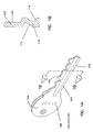
- Figure 1A illustrates the various component parts of a key 100.
- the key shaft 102 extends from the key bow 104.
- the key bow 104 is the portion typically held by the user when using the key.
- the shaft 102 has a keycode 106 along one edge.
- the bow 104 may be provided with a numerical code 108 that corresponds to the keycode 106.
- the cross section of the shaft 102 has a particular shape, known as the keyway 110.
- the profile of the keyway 110 is illustrated in FIG. 1B, which shows a cross section 1B-1B through the shaft 102.
- the keyway 110 illustrated includes a notch 112 on a first side of the shaft 102 and another notch 114 and land 116 on the second side of the shaft 102.
- the notches 112 and 114 and land 116 run the length of the shaft and mate with the aperture of the lock when the key 100 is inserted.
- the key shown in FIGs. 1A and 1B is only an example of a key and is not intended to limit the scope of the invention in any way.
- the key 100 may be a double-sided key, in which case the keycode is found on opposite edges of the shaft.
- the same keycode is provided on each edge of a double-sided key so that it may be inserted into the lock in either orientation.
- keys come with many different keyway profiles. Indeed, it is one of the major problems in the key industry that, due to the large number of different keyways, a large number of key blanks have to be held in inventory.
- FIGs. 2-5 illustrate one particular embodiment of a key-duplicating apparatus 200.
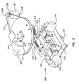
- FIGs. 2 and 3 illustrate the key-duplicating apparatus 200 in an "original-measuring" mode, in which the original key 202 to be copied is measured for its keycode 242 and keyway 240.
- FIGs. 4 and 5 illustrate the key-duplicating apparatus 200 in a "key-fabricating" mode, in which a duplicate key is cut from a blank preform 246. The preform 246 is held between the key holder 204 and a tip holder 248.
- a key 202 is held by a key holder 204.
- the key holder 204 holds the bow 206 of the key 202 so that the shank 208 is accessible by the measuring device 210 and the cutting tool 212.
- the key holder 204 is mounted on a translation stage 214 that travels in the x-direction.
- the x-translation stage is driven by a stepper motor 216.
- the x-translation stage 214 is mounted on top of a second translation stage 218, oriented for translation in the y-direction.
- the y-translation stage 218 is driven by a stepper motor 220.
- the y-translation stage 218 is mounted on a third translation stage 222 which provides translation in the z-direction.
- the z-translation stage 222 is driven by another stepper motor 224.
- the stepper motors 216, 220, and 224 are controlled by a controller (not illustrated) so that the key can be positioned at any point in x, y, z within the range of travel of the translation stages 214, 218 and 222.
- a rotatable platform is positioned above the key holder 204 and the stack of translation stages 214, 218 and 222.
- the rotatable platform 226 holds the measuring device 210 and the cutting tool 212.
- the rotatable platform 226 is rotated using a rotator drive 228.
- the rotator drive 228 is used for rotating the rotatable platform 226 between two positions, namely: a) the cutting tool 212 being perpendicular to the key shank 208, and b) the cutting tool 212 being parallel to the key shank 208. Accordingly, the rotator drive 228 rotates the rotatable platform 226 between two positions, separated by 90°.
- the rotator drive 228 includes a stepper motor 230 and a drive belt 232 positioned around the periphery of the rotatable platform 226 and a pulley 234 mounted on the shaft 236 of the stepper motor 230.
- the key holder 204 is also rotatable, and its rotating motion is controlled by a second rotary stepping motor 238, illustrated in FIGs. 4 and 5. Accordingly, the key 202 may be rotated for measuring either its keycode or its keyway.
- FIG. 2 illustrates the key 202 oriented with its keycode directed towards the measuring device 210 so that the key-duplicating apparatus 200 can measure the keycode 242 of the key 202.
- Figure 3 illustrates the same apparatus as FIG. 2, except that here the key 202 has been rotated through 90° into position for measurement of the keyway 240 by the measuring device 210.
- the rotatable platform 226 is mounted to an apparatus frame (not illustrated) by a rotatable bushing 244.
- Figure 4 illustrates the cutting tool 212, including a number of edge cutters 250 used for cutting the keyway profile, a key-code cutter 252, and a wire brush 254 arranged on a shaft 256.
- the shaft 256 is supported at either end by shaft supports 258 that are attached to the underside of the rotatable platform 226 (shown in dashed lines in FIGs. 4 and 5).
- the shaft 256 is rotated by the cutting tool motor 260.
- Figure 4 illustrates the apparatus 200 in a "keyway cutting" mode, with one of the edge cutters 250 forming a groove along the preform 246 to make a keyway 262.
- the edge cutters 250 are selected so as to provide a variety of shapes of cutter profiles for cutting the keyway 262 into the blank preform 246.
- Figure 5 illustrates the same apparatus as in FIG. 4, but in a "key-code cutting" mode.
- the blank preform 246 has been rotated through 90° from the position illustrated in FIG. 4.
- the rotatable platform 226 has been rotated through 90° so that the shaft 256 is parallel with the blank preform 246.
- the blank preform 246 has been brought into position by the x-, y- and z-translation stages 212, 218 and 222 so as to engage the keycode cutter 252 on the edge of the blank preform 246.
- the blank preform is translated relative to the keycode cutter 252 by the x-, y- and z-translation stages 214, 218 and 222 as the keycode cutter 252 is rotated by the cutting tool motor 260.
- the keycode 264 is cut into the edge of the key according to the relative movements of the translation stages 214, 218 and 222.
- edge cutters 250 that may be provided on the shaft 212, are illustrated in FIG. 18.
- the edge cutters 250 are selected to provide the apparatus 200 with a wide capability for cutting different types of keyway profiles.
- the right- and left-angled cutters 1800 and 1802 permit angled channels to be cut. Channels having side slopes less steep than the cutters 1800 and 1802 may be cut using a procedure having a series of multiple passes.
- Use of flat cutters 1804, 1806 and 1808 results in the removal of material leaving a flat finished surface.
- the flat cutters 1804, 1806 and 1808 are provided in a variety of widths.
- the narrowest flat cutter 1804 may be used, for example, to cut a flat bottom into a narrow channel.
- the widest flat cutter 1808 may be used for cutting down large portions of the preform, for example in reducing the original thickness of the preform to the thickness of the original key 202 that is being duplicated.
- Use of the rounded cutter 1810 results in a rounded channel.
- the rounded cutter has only one radius of curvature, channels having different radii may be formed by controlling the movement of the preform 246 in all three directions x, y, and z while the channel is being cut.
- the "V" cutter 1812 has a "V" profile to cut a v-shaped channel.
- the selection of edge cutters 250 illustrated here is not intended to limit the invention. It will be appreciated that additional edge cutters, having shapes different from those illustrated here, may also be employed in forming the keyway.
- FIG. 6 illustrates an optically based measuring device for measuring the keycode and the keyway of the key which is to be duplicated.
- the measuring device 610 employs a laser 612, or other light source, to direct a light beam 614 which is collimated by collimating lens 616.
- the measuring device 610 includes collection optics 618 for receiving a light beam deflected by a target, and a linear photo-detector array 620 that detects the light collected by the collection optics 618.
- the laser 612 and the photo-detector array 620 are both coupled to an electronics package 622 which controls the output from the laser 612, and receives the detected signals from the photo-detector array 620.
- the electronics package 622 may also analyze the detected signals before directing data along communications link 624 to a control processor.
- the processor may also direct control signals into the measuring device 610 through the communications link 624. It will be appreciated that other detectors, such as a position sensitive optical detector or the like, may be used for detecting a position of the light beam.
- the measuring device 610 operates as follows.
- the collection optics 618 and the photo-detector array 620 receive light deflected (scattered or reflected) from a target which is spaced from the measuring device 610 by a certain distance. If the target 626 is positioned at a nominal distance, then the light deflected by the target 626 and received by the collection optics 618 is consequently directed onto the photo-detector array 620 at position A. If the target 626' is positioned further from the measuring device 610 than the nominal distance, then the light (shown as a dash-dotted line) deflected the target 626' and collected by the collection optics 618 illuminates a different portion of the photo-detector array 620, shown as position B.
- the target 626' is positioned closer to the measuring device 610 than the nominal distance, then the light (shown as a dashed line) deflected by the target 626 and collected by the collection optics 618 illuminates the photo-detector array at a different position, illustrated as position C. Therefore, by detecting the position on the photo-detector array of the deflected light from the target, the distance to the target may be estimated. In one mode of operation, the position of the target 626 is varied relative to the measuring device 610 until the light collected by the collection optics 618 illuminates the photo-detector array 620 at position A.
- the speed of translation of the translation stages may be adjusted, depending on how far the key 202 is measured to be away from the nominal separation from the measuring device 610. For example, if the key 202 is determined to be relatively far from the nominal separation, then the translation speed may be high. Once the target key is determined to be within a predetermined range of the nominal separation, then the translation speed may be set to be slower, and the translation speed is reduced to zero once the key is at the nominal separation.
- a numerical profile of the key 202 corresponding to its physical shape can be constructed by tracking the amount of translation in three dimensions required to achieve the nominal separation between the measuring device 610 and a series of measurement points along the key 202.
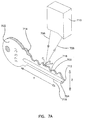
- Figure 7A illustrates the measurement of a keycode 700 on a key 702 using a light-based measuring device 710.
- a light-based measuring device 710 uses an optical interaction, such as reflecting, scattering or blocking a light beam, to produce an optical signal that can be used in determining the position of a point on the key 702. It is assumed that the shank of the key 704 is aligned parallel with the y-axis.
- the measuring device 710 transmits a first light beam 706 to illuminate a spot on the edge of the key shank 704, designated as spot A.
- the light 708 deflected to the photo-detector 710 is detected by the collection optics and photo-detector array which determines whether point A is at the nominal distance, or either closer or further from the nominal distance.
- the detected light may be reflected or scattered by the key 702.
- the position of the key 702 is altered accordingly, to bring position A to the nominal distance.
- the position of the key 702 is recorded by tracking the movements of the translation states to achieve the nominal separation between point A and the measuring device 710.
- the key 702 is then translated in the y-direction so that the first light beam 706 illuminates point B, positioned close to point A but spaced by a pre-selected separation in the y-direction.
- the process of positioning point B at the nominal distance relative to the measuring device 710 is repeated, and the amount of translation in the y- and z-directions required to move position B to the nominal distance are noted.
- the key is then translated again in the y-direction so that position C is illuminated by the first light beam 706.
- the key is adjusted in the z-direction to position point C at the nominal distance from the measuring device 710. Again, the amount of translation in y and z to place point C at the nominal distance is recorded. This procedure is repeated over the entire length of the key shank 704, from the tip 712 to the stop 714, so that the whole keycode 700 is measured.
- the second edge 716 of the key shank 704 may also be measured. Where the key 702 is single-sided, as illustrated in FIG. 7A, then the measurement along the second edge 716 yields a straight line.
- the keycode 700 is provided on either edge of the key shank 704.
- a double-sided key is typically rotationally symmetrical about an axis along the center of the key shank 704 so that the keycodes provided on the edges of the shank are identical and the keyways are the same on both sides of the key 702.
- the measurement on both edges of the key 716 and 718 provides independent measurements of the keycode 700. It is an important feature of the present invention that since both edges of the key shank 704 are measured, it is possible to duplicate a key where the keycodes cut on either edge are different from each other.
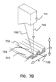
- Figure 7B illustrates the measurement of a keyway profile on the key 702.
- the process of measuring the keyway profile 720 is similar to that used in measuring the keycode 700.
- the key 702 is rotated through 90° relative to the orientation used for measuring the keycode 700 so that the measuring device 710 can illuminate portions along the side 722 of the key shank 704.
- the keyway profile 720 is measured by positioning successive spots across the side 722 of the key shank 704 at the nominal distance from the measuring device 710.
- the measurement of the keyway profile 720 is advantageously made at the widest portion of the key shank 704 so that measurement of the entire keyway profile 720 is assured.
- the widest portion of the key shank 704 may be deduced from the measurements of the keycode 700 performed earlier.
- the key 702 may not always be aligned exactly with the axis of the translation stages. However, it will also be appreciated that any deviation from such alignment may be accounted for in the software driving the translation of the translation stages. Thus, in the measurement of both the keycode and keyway, the key 702 may be translated in all three directions - x, y and z - to perform the measurement.
- a detector may be positioned on a side of the key 702 opposite from the light source.
- a point on the keycode may then be detected by moving the key across the light beam so as to cut off the light beam passing to the detector, and recording the positions of the translation stages when the beam is cut off. This may be performed for a number of points along the keycode, so as to "map" the profile of the keycode.
- the keycode 700 and the keyway 720 of the key 702 may be measured using other methods.
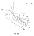
- One such method is illustrated in FIG. 7C, where the keycode 700 is measured using a mechanical follower 724.
- the mechanical follower 724 has a small tip 726 that is sensitive to a force applied when brought into contact with the key edge 718.
- the steps for measuring the keycode 700 are similar to those discussed regarding the light-based measuring device, where a series of points along the edge 718 of the key 702 are brought into a specific position in three-dimensional space by adjusting the translation stages on which the key is mounted. The specific position in three-dimensional space is defined by the tip 726 of the mechanical follower 724.
- Figure 7D illustrates the mechanical follower 724 in use for measuring the keyway profile 720 of the key 702.
- the tip 726 of the mechanical follower 724 defines a point in three-dimensional space to which a series of positions across the shaft 704 of the key 702 are brought into contact.
- the keyway profile 720 can be measured.
- both sides of the shank 704 are measured to produce a complete keyway profile.
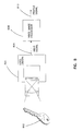
- Figure 8 illustrates an embodiment of a measuring device that utilizes a video camera for measuring the profile of a key 802.
- An image of the key 802 is recorded by the video camera 804, which converts the optical image into a video signal.
- the video signal is transmitted on the video line 806 to the video image processor 808.
- the video image processor 808 converts the received video signal into key profile data using, for example, a pattern recognition technique.
- the key profile data contain information on the dimensions and shape of the key imaged in the camera 804.
- the key profile data are then converted into a series of motion control signals to control the movement of the translation stages for cutting the duplicate key.
- This video approach to key measurement may provide all the required profile information using two images, one image taken from the side of the key 802 as illustrated to provide keycode information, and the other image taken of the key tip in a direction along the axis of the key 802 to give keyway information.
- a video measurement system requires the video camera 804 and the key 802 be movable relative to each other in such a way as to permit side-on and end-on views to be taken.
- a video camera could be mounted on a rotating mount, for example, to allow an image to be taken of the side of the key 802 and the end of the key 802, while the key 802 remains stationary, or two fixed mount cameras 804 could be employed in orthogonal orientations.
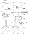
- FIG 9 illustrates a block schematic of an embodiment of a control system for the key-duplication apparatus that may be used to control the embodiment of the duplicating apparatus illustrated in FIGs. 2-5.
- the control system 900 is based on an embedded PC central control system 902 having a number of plug-in interfaces for interfacing with various subsystems of the apparatus.
- the control system 902 may include a memory device 904, such as a read only memory, erasable read only memory, magnetic tape or disk, CD-ROM, or the like for storing information.
- the central control system 902 controls several motors 216, 220, 224, 230, and 238 via the plug-in motor interface 914.
- the x-axis stepper motor 216 controls the x-position of the key and the blank preform.
- the y-axis stepper motor 220 controls the y-position of the key and the blank preform, and the z-axis stepper motor 224 controls the z-position of the key and the blank preform.
- the a-axis stepper motor 238 controls the orientation of the key 202 and the blank preform 246 in the key holder 204, so that an edge or a flat surface is presented to the key-duplication apparatus 200 for measurement or cutting.
- the b-axis motor 230 controls the rotational position of the cutting tool 212 so that the cutting tool 212 can cut either parallel or perpendicular to the axis of the key shank or the axis of the blank preform 246.
- the measuring system 210 is coupled to the central control system 902 via the plug-in measuring interface 918.
- the measuring system 210 transmits measurement data to the central control system 902 during measurement operations. For example, while measuring the keycode of a key, the measuring system 210 transmits information to the central control system 902 related to the relative position of the point on the key being measured to the nominal position.
- the central control system directs the x-, y- and z-axis motors 216, 220 and 224 accordingly to move the measurement point on the key into the nominal position.
- the motor interface 914 may also relay step completed information to the control system 902 so that the control system 902 maintains tracking of the position of the stepper motors 216, 220, 224, 230 and 238.
- a user may interact with the apparatus via a display 920 and a keypad 922, which are interfaced with the central control system 902 via the plug-in operator interface 924.
- the display 920 is used for displaying information to the user concerning, for example whether or not the submitted key can be duplicated.
- the user may enter data, information or commands to the central control system 902 via the keypad 922.
- Such information or commands may include how many duplicate keys are to be produced from the submitted original key.
- the central control system 902 controls the speed and direction of the cutting tool motor 260 according to the type of operation. For example, the cutting motor may operate at slower speeds for cutting the keyway profile than for the cutting the keycode, since there is typically more material to be removed when cutting the keyway than when cutting the keycode. Also, when deburring with the wire brush, the cutting tool motor 260 may be operated at a higher speed than during a cutting operation, and in both directions.
- the key holder may be operated by a solenoid 928 so as to automatically grip and release the key and blank preform from the holder.
- a communications interface 940 is connected to the control system 902 which provides for communication with external sources.
- the communications interface 940 may include a telephone modem that permits the control system 902 to receive information on the shape and dimensions of standard keycode elements from key manufacturers, or to receive a listing of known key types (combinations of keyway and keycode) that have been reported to be stolen.
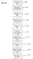
- a list of process steps for measuring a key are provided in FIG. 10. Initially, the key 202 that is to be copied is inserted in the key holder 204, at step 1000. The first keycode 242 is measured along the first edge of the key 202, at step 1002. The key 202 is then rotated through 180° in the key holder 204 to expose the second edge of the key 202 to the measuring system 210, at step 1004. The keycode profile of the second edge of the key 202 is then measured, at step 1006. Measurement of both edges of the key 202 provides information for the subsequent cutting process.
- the controller 900 may determine if the key 202 is held in the key holder 204 with the longitudinal axis of the key parallel to a translation axis of the apparatus 200, or whether there is an angle between the key axis and the translation axis. The determination of such an angle permits the controller 900 to include the angle in subsequent analysis of the measurement data and development of cutting instructions. However, the operator may also indicate to the controller 902 that the key is single-sided, for example via the operator interface 904, thus ordering the apparatus to measure only the first edge of the key 202.
- the key 202 is then rotated through 90° in the key holder 204, at step 1008, thus exposing the first side of the key to the measuring system 210 so that the keyway on the first side may be measured.
- the controller 902 determines from the measurements of the keycodes where the widest point of the key blade is located, and the measurement system 210 is positioned at the widest point, at step 1010. This ensures that subsequent measurements of the keyways on either side of the key 202 include the complete keyway.
- the keyway profile of the first side of the key 202 is measured, at step 1012.
- the key 202 is then rotated through 180° to expose the second side of the key 202 to the measuring system 210 at step 1014.
- the keyway profile on the second side of the key 202 is measured, at step 1016.
- the key 202 may then be removed from the key holder 204, at step 1018.
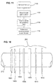
- FIG. 11 A sequence of steps for making a measurement of a keycode or keyway is provided in FIG. 11.
- the apparatus 200 is calibrated by setting the positions of the translation stages 214, 218, and 222 at a fiduciary zero for all three axes, x, y, z, at step 1100.
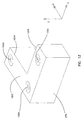
- the zeroes are set for each axis by setting the measurement 210 to locate the x-axis, y-axis, and z-axis zero steps on the system calibration standard block 270, illustrated in FIG. 2.
- This block is shown in greater detail in FIG. 12.
- the block 270 includes a number of bolt holes 1200 to receive bolts so that the block 270 can be firmly attached to the x-translation stage 214.
- the upper surface 1202 of the block 270 acts as the z-axis zero reference.
- the block also has two edges 1204 and 1206 which act as x- and y-axis reference zeroes, respectively.
- the initial zeroing of the apparatus 200 is performed by locating the zero surfaces and edges of the block 270 using the measuring unit 210.
- the x- and y-axes are zeroed when the measuring unit detects their respective zero-edges 1204 and 1206.
- the z-axis is zeroed on the top surface 1202 of the block 270.
- the machining axes, x, y, and z are provided with end-of-travel motion limit switches.
- the calibration block is located just inside the limits of the x, y, and z travel and is initially found by first slewing each axis to its respective zero end limit switch, then stepping off the switch until the measuring unit 210 detects the appropriate reference edge or surface of the block 270.
- the zeroes for each axis are located close to the end of the travel on each axis.
- the two rotary axes are stepped in one direction until their zero limit switch is encountered, and then stepped away to the point of signal loss.
- the x, y, and z translation stages 214, 218, and 222 are slewed to locate the beginning point for the first scan, at step 1102.
- the scan start position is located outside of the maximum expected envelope of space for the key geometry to be measured, and may be simply a point in space relative to the zeroed point.
- the scanning translation stages are slewed to detect where the key geometry starts, at step 1104.
- One or more of the translation stages 214, 218, and 222 is slewed until the measuring unit 210 detects the presence of a key surface.
- the z-axis is advanced or retracted to null the scan standoff distance, i.e., to set the nominal separation between the key surface and the measuring unit 210.
- the distances from the previously set zeroes traveled by the translation stages 214, 218, and 222 are recorded.
- the geometry of the key is followed and recorded up to the end of that particular scan, in step 1106, using the step and repeat process described above with regard to FIGs. 7 and 8.
- the scanning axis is stepped to scan to the next position to be measured. Holding the scan at the reference position, the z-axis is stepped up or down to achieve the nominal separation from the measuring unit.
- the axis positions are recorded. A new reference position is found and the translations of each translation stage 214, 218, and 222 are recorded.
- the axis positions thus recorded represent a digitized form of the key shape that has been scanned, offset by the z-axis stand-off distance.
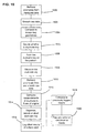
- a sequence of steps for machining a duplicate key using the measurements of the original key are listed in FIGs. 13 and 14.
- the preform is inserted into the holder 204 and held at its far end by the tip holder 248, in step 1302.
- the keyway on the first side of the preform 246 is machined using the edge cutters 250, in step 1304.
- the preform 246 is then rotated through 180°, in step 1306. If not already done, the sequence of cuts for forming the second keyway on the second side of the preform 246 is developed, in step 1308.
- the second keyway on the second side of the preform 246 is then machined using the edge cutters 250, in step 1310.
- the preform 246 is then rotated through 90°, in step 1312, to expose a first edge to the keycode cutter 252.
- the platform 226 is rotated through 90°, in step 1314 so that the shaft 212 lies parallel to the preform 246, and the keycode cutting tool 252 is correctly oriented relative to the preform 246.
- step 1316 numerical instructions for cutting the keycodes on the preform 246 are developed in step 1316.
- the first keycode is machined on the first edge of the preform 246, at step 1400.
- the preform 246 is then rotated about its axis by 180° to expose the second edge to the keycode cutter 252, in step 1402.
- the second keycode is then machined on the second edge of the preform at step 1404.
- the second keycode pass may be only for cutting the backside edge of a single sided duplicate.
- the machined preform 246 may be separated from its tip held in the tip holder 248.
- the machined preform represents a duplicate of the original key.
- the duplicate key is deburred, in step 1406, using the wire brush 254 to remove any burrs or cuttings, and to soften any sharp edges which may be dangerous to a user.
- the platform 226 is rotated back into position, which permits measurements to be made of the duplicate key, in step 1408.
- the keycodes and keyways of the duplicate key are measured, in step 1410, and compared with those of the original key 202, in step 1412. Any variances between the two measurements are noted, in step 1414, and a flag is set, in step 1416, if the variances in measurement between the original key 202 and the duplicate key exceed a predetermined threshold, for example a few thousandths of an inch. Any variances thus measured may be indicative of wear on the key-duplicating apparatus 200: this is discussed further hereinbelow.
- the duplicate key is then removed from the apparatus, at step 1418.
- a sequence of steps for analyzing measured key profile data are provided in FIG. 15.
- First, any anomalies or glitches present in the data measured from the original key are removed, in step 1500. This is done using generalized key-shape knowledge to remove any possible abnormal details that the measuring unit 210 might generate in error.
- Next, the raw data are smoothed, in step 1502, using a smoothing algorithm to mathematically smooth the scanned data.
- the measured key shape is compared to known key geometries, in step 1504.
- the measured key shape is compared to stored, known key-shape data, for example, as supplied by key manufacturers, to determine if a match might exist.
- Key-shape data may be downloaded to the apparatus 200 via a telephone or other communications link through the communications interface 940, or may be stored locally in the memory device 904. These data may include key shapes of high security keys whose duplication is forbidden, or combinations of keyway profiles and keycodes for keys that have been reported to be lost or stolen.
- a decision is then made, based on the results of the comparison in step 1504, on whether or not to duplicate the measured key.
- the shape of the standard key may be used for the instructions for cutting the duplicate, rather than the measured data, since the measured key may be worn and may no longer retain the same shape and size as when new.
- a signal may be directed through the communications interface 940 to another location, such as a manufacturer's information desk or the police.
- the duplicate key is then formed on the preform 246, in step 1506, using the measured, de-glitched, and smoothed data to machine the duplicate.
- the duplicate key is then measured in step 1508 and the anomalies removed and the raw data smoothed, in step 1510.
- the measurements of the duplicate key are compared with those of the original key 202, in step 1512.
- a decision on whether to accept the duplicate key, rework the duplicate key or abort the duplicate key is made in step 1514. This decision is made on the results of the comparison in step 1512. If the measurements of the duplicate key are acceptably accurate in comparison with the measurements of the original key 202, then the duplicate key is deemed to be acceptable.
- a flag may be set to indicate if the duplicate key is to be aborted.
- a new preform may then be loaded into the holder 204 and tip holder 248 and a new duplicate key cut.
- the offset between the measurement results for the original key 202 and the duplicate key are logged, in step 1516, along with a listing of which edge cutters 250 were used in cutting the keyways on the preform 246.
- the edge cutters 250, the keycode cutting tool 252, and the motion system, including the translation stages 214, 218, and 222 may wear with use. Such wear can be compensated for in gradual increments by keeping a record of the machine and specific cutting performance after each use.
- the logged results are compared to previously logged results in step 1518. By comparing the results after each usage to previous results, sudden changes in system performance can be discovered. By comparing the present results to older or average data, the controller can make decisions on how to gradually compensate for machine or cutter wear.
- step 1520 Any cutter or machine maintenance needs are flagged, in step 1520, for example, by sending a message to the display 920 or through the communication interface 940 to a maintenance desk.
- the gradual compensation discussed with regard to step 1518 reaches certain preset limits, the particular cutter or machine element showing excessive offset or error is flagged for future repair or replacement.
- This maintenance status log may be available for uploading to a central monitoring station, or displayed on the display 920.
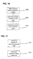
- a sequence of steps for producing cutting instructions for a keyway is illustrated in FIG. 16.
- a match is made between the measured keyway profile and the cutters required to cut the profile, in step 1600.
- the shape geometry of the keyway profile is matched to one or more edge cutters 250.
- the processor selects for each keyway channel the keyway cutter that will remove the most material and will most closely approach the profile without overcutting, for the first pass.
- Each channel of the keyway on each side of the key may require multiple machining passes using more than one edge cutter 250 to produce the profile line within the acceptable profile tolerance.
- the machine stroke is generated for producing the keyway.
- the stroke or pass pattern is computed that approximates the keyway profile shape within the acceptable profile tolerance.
- Each keyway channel is computed for each side of the key individually.
- the keyway cutter selection order is then optimized, in step 1604.
- One method of optimizing the selection order is to order of cutter passes per channel so that minimizes cutter selection motion, i.e. the transverse motion of the preform 246 to move from one edge cutter 250 to another is reduced, while permitting maximum material removal per pass. This method may be used to minimize the time to complete a given keyway side.
- the keyway on the first side of the preform 246 is completed prior to rotating the key for machining the keyway on the opposite side.
- step 1700 the usability of the scanned keycode data is determined, in step 1700.
- Keycode data that is either too heavy or too thin may be the result of measuring from a worn key or an oversized duplicate of the manufactured key.
- the controller 900 may request from the user, for example, through the display 920, whether compensation should be applied and also whether the key may be oversized or worn.
- the duplicate key can then be made according to standard keycode increments for the style and geometry of the original key 202. If the keycode data are not generally offset, but instead are incrementally offset, then the controller may decide that no compensation for wear or oversized conditions should be included.
- the keycode cutting sequence is generated, in step 1702.
- Keycodes are machined in a single direction pass per edge, starting at the key bow and progressing to the key tip.
- the keycode cutter 252 is positioned perpendicular to the keyway access on the key bow side, flat on the perimeter, and 45° beveled on the key tip side.
- the keycode cutter is oriented with the rotating access parallel to the keyway access.
- a continuous machining pass is started with a plunge cut at the key bow end, followed by side cutting with angled transitions either in or out to reach and machine each keycode step of the key.
- Double-sided keys are machined on each edge sequentially. Keycode passes may be repeated at incremental depths, and/or partial passes until the final geometry is reached.
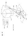
- FIG. 19 A system for monitoring a keyway profile using structured light is illustrated in FIG. 19.
- the system 1900 includes a laser stripe generator 1902 that illuminates the key 1904.
- the laser stripe generator generates a beam of light 1906 that comes to a line focus 1908 on the surface of the key 1904.
- the laser stripe generator may be, for example, the model SNF-501L-670S-5-10, produced by Lasiris Inc. This model is capable of producing a focused line about 15 mm in length (0.6") and 38 ⁇ m wide (0.0015”) at a stand-off distance of about 90 mm (3.5").
- a video camera 1910 such as a 2-D CCD camera, is positioned above the key 1904 to receive light deflected from the line focus 1908 on the surface of the key 1904.
- the camera 1910 may be, for example, a high resolution, monochromatic video camera such as the model TM-7 produced by Pulnix, the Hitachi KP-M2, and the Costar CV-M50.
- a high resolution camera typically has a CCD detector with 768 x 494 pixels, although other sizes of CCD detector may also be used. It will be appreciated that the measurement resolution of deep features on the surface of the key 1904 may be affected by the depth of field of the light beam 1906.
- the axis of the camera 1910 is positioned at an angle relative to the direction of the light beam 1906. Therefore, the camera detects a lateral shift in the position of the line focus 1908 arising from a change in the height of the surface.
- the angle is selected to be 45°, as illustrated, a unit change in the height of the surface causes a unit change in the lateral position of the light stripe on the surface of the key 1904.
- the line focus 1908 is positioned at a point along the key where the key blade 1912 is widest, thus ensuring that the measurement of the keyway profile covers all the features of the keyway.
- the detection data are passed to a processor, 1914, which may include a screen grabber, for analysis.
- the processor 1914 analyzes the data to determine the shape and size of the keyway profile. Once the profile is determined, the processor 1914 assembles machining instructions for cutting the measured keyway profile into the blank preform.
- FIG. 20 shows the measured profile for the key 1904 of FIG. 19.
- the end portions 2002 of the signal correspond to those portions 1922 that are incident on the supporting surface for the key shown in FIG. 19.
- the outer edges of the key shown at points A and B correspond to shoulders 1923 and 1925.
- the long portion of the signal 2004 corresponds to the portion 1924 that lies between the first shoulder 1923 and the groove 1913.
- the angled portion of the signal 2006 corresponds to the angled face of the groove 1913.
- the remaining flat portion 2008 of the signal corresponds with the short flat section from the groove 1913 to the second shoulder 1925.
- the signal 2000 is shown plotted as a function of distance in two dimensions.
- the data may also be stored digitally, and converted to distance measurements where a calibration factor for pixel spacing is known.
- the light projector may scan a spot across the key to resemble a line focus.
- the detector may also be a 1-D detector array that is translated across the field of view to generate a series of 1-D images that form a composite 2-D image.
- FIG. 1A shows a key 100 with a key code 108 stamped on the key bow 104.
- the key code 108 contains information only related to the keycode 106.
- the key code 108 may be configured to contain information related to the keyway 110.
- a user may be able to read the number off the key bow 104 and refer to a look-up table or otherwise process the information provided by the number to identify the keyway profile associated with the code 108 read from the key bow 104.
- a video camera may be used to record an image of the key code 108 and the results analyzed to determine the code read off the key 100 by the camera. After determining the code, the code could be used, for example, with a look-up table to relate the code read off the key 100 with the key's keyway profile. Additionally, the code provided by the key, in this embodiment or any other embodiment described herein, may include machining instructions for the processor to follow.
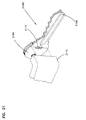
- the key 2100 may include a code, such as a bar code 2112 on the key bow 2104.
- the bar code may be read by a bar code reader 2114, and the code that is read off the key 2100 then related, such as through a look-up table or other method, to the keyway profile 2106 of the key 2100.
- the bar code reader 2114 may operate in a manner similar to bar code readers as are used in offices and supermarket sales check-out units, where the bar code reader 2114 illuminates the key 2100 with a line of light, and the code 2112 is read from the light reflected by the bar code 2112.
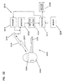
- FIG. 22 Another method of determining the keyway profile of a key, particularly useful for car keys that include a security transponder, is illustrated in FIG. 22.
- the key 2200 is of the type commonly used as a car door and ignition key, where the key bow 2202 contains a miniaturized RF transponder 2204. This type of key is often used to provide extra security because a transmitter located in the steering column of the car interrogates the key 2200 once it is placed in the ignition. If the transponder 2204 does not respond with the correct code, which may be a 64-bit digital code, then the car's ignition is disabled.
- the RF transponder 2204 is typically inductively powered by the transmitter.
- the transponder 2204 may also be used to identify the keyway profile 2206 of the key 2200.
- the system 2210 used for interrogating the key 2200 includes a processor 2212 that generates an interrogation signal which is converted into a transmissible signal in the transmitting unit 2214.
- the interrogation signal 2216 is transmitted by an antenna 2218.
- the transponder 2204 in the key 2200 responds by transmitting a response signal 2220 that is received by the antenna 2218 and detected in a detector 2222.
- the detected signal is typically analyzed and amplified in the amplifier and analyzer 2224 where it is converted into processor-readable form, before being returned to the processor 2212.
- the processor 2212 is connected to a memory 2226 that typically contains a look-up table that relates the response code received from the key 2200 with the keyway profile 2206. After the processor 2212 has determined which keyway profile 2206 is associated with the response code received from the key 2200, the processor 2212 generates machining instructions for the machine control unit 2228 that controls the cutting tools used to cut the appropriate keyway in the key preform.
- the system 2210 interrogates the key 2200 and receives the identification code back from the transponder, at step 2302.
- the received data are analyzed, at step 2304 and then passed to the processor 2212 in a form suitable for the processor 2212. If applicable, the processor 2212 determines which portion of the received code corresponds to keyway profile information, at step 2306.
- the processor determines, for example using a look-up table, which particular keyway profile is associated with the identification code, at step 2308.
- the processor then forms a set of machining instructions for cutting the keyway profile in the key preform, at step 2310. These instructions are passed to the machine controller 2228 that controls the cutting tools.
- the key may optically transmit a response signal, for example in the visible or infrared portions of the spectrum, rather than an RF response signal.
- the key may receive an optical interrogation signal, using a photodetector rather than an RF receiving antenna.
- the key 2400 includes an electronic circuit, typically in the bow portion 2402, that is provided with electrical contacts 2404.
- the key 2400 may be placed in a key reader 2410 that includes reader contacts 2412 that mate up with the key contacts 2404.
- the reader contacts 2412 are connected, through an input interface 2414, with a processor 2416.
- the processor 2416 can interrogate the electronic circuit for information related to the keyway profile.
- the information supplied by the key may include a description of the keyway profile, but more likely includes a code that the processor 2416 can use with a look-up table stored in a memory unit 2418 to determine the keyway profile.
- This method has similarities to that described above in connection with FIGs. 22 and 23, but where the signals passed between the processor 2416 and key 2400 are electrical. Once the processor 2416 has determined which keyway profile is associated with the key 2400, the processor 2416 can generate or retrieve machining instructions to pass on to the machine control unit 2420 that controls the machining process when fabricating the keyway profile in the key preform.
- the duplication apparatus may be provided with two holders, one for holding the key to be copied and the other for holding the preform.
- the apparatus may be inverted or rotated to allow cutting scraps to fall free of the machine elements.
- the processor may incorporate the machine control unit that controls the formation of the duplicate key.
- the duplicating apparatus may simply measure the keyway of the original key and duplicate the keyway in the preform, and may also duplicate the remainder of the keycode if necessary.
- the present invention is applicable to duplicating keys from original keys from a blank preform. It is believed to be particularly useful in producing duplicate keys where it is desirable to reduce the expected degree of skill of the operator and to reduce the number of rejected duplicates. Accordingly, the present invention should not be considered limited to the particular examples described above, but rather should be understood to cover all aspects of the invention as fairly set out in the attached claims. Various modifications, equivalent processes, as well as numerous structures to which the present invention may be applicable will be readily apparent to those of skill in the art to which the present invention is directed upon review of the present specification. The claims are intended to cover such modifications and devices.
Landscapes
- Engineering & Computer Science (AREA)
- Mechanical Engineering (AREA)
- General Factory Administration (AREA)
- Length Measuring Devices By Optical Means (AREA)
Abstract
Description
- The present invention is directed generally to a method and apparatus for making a copy of a key.
- Hundreds of millions of keys are generated in the United States each year by making a duplicate from an original key or from a parent duplicate key. The duplication process commonly takes place in a hardware store, or the like, that is equipped with a key duplication machine. US Patent No. 3682041 describes a method and apparatus for duplicating a key, wherein a key to be duplicated is held and contacted with tracer rods, the tracer rods being mechanically coupled to cutting bits. As the tracer rods move along the surface of the key to be duplicated, the cutting bits simultaneously cut the surface of the key to be duplicated in a key blank.
- Duplicating a key is difficult task, typically requiring high skill in operating the duplicating machine. A high degree of skill is particularly required when duplicating a double sided key in order to achieve correct registration of the second side after cutting the first side. Due to the high probability of making an error when duplicating a key, a significant number of the duplicate keys made each year are discarded as being unusable.
- Since there is a wide variation in the types of keys manufactured, the locksmith or hardware store where the duplicate is made has to carry a large number of different key blanks, often numbering in the thousands, in inventory from which an appropriate blank is selected for forming the duplicate key. When faced with duplicating a key of unknown origin, the person performing the duplication is presented with the difficult task of selecting the correct key blank with which to manufacture the duplicate. This may lead to the selection of the wrong key blank, thus resulting in an unusable duplicate key.
- The security hierarchy adopted by many key manufacturers includes thicker keys with relatively complex keyways for use in single locks, and master keys that are thinner and have relatively simple keyways. Often, master key blanks are employed for forming duplicate keys in an attempt to reduce the number of key blanks required in inventory, irrespective of whether the key being duplicated is a master key or is cut for a single lock. Consequently, the security hierarchy is compromised when a large number of keys cut from master key blanks enter into use.
- One manufacturer has adopted a system that uses a small number of key blanks in which it is claimed most keys can be duplicated, thus reducing the level of skill required of the person performing the duplication. However, this system still requires a significant inventory of different key blanks and, additionally, is subject to the problem of low-skilled operators making a large number of rejectable duplicate keys.
- Therefore, there remains a need for a key duplicating system which further reduces the number of types of key blanks required to be carried in inventory. Additionally, there is a need to remove the factor of operator skill level from the duplication process so that fewer rejectable duplicate keys are manufactured.
- According to an aspect of the present invention, there is provided an apparatus and method for duplicating an original key by determining the keyway of the original key, selecting a tool for forming a second keyway in response to a control signal based on the keyway determination from the first key and forming a second keyway in a key preform with control signals based on the keyway determination from the first key. In one embodiment of the invention, the keyway of the original key is measured and formed in the duplicate key. In another embodiment of the invention, both the keycode and the keyway of the original key are measured and formed on the duplicate key.
- The preform from which the duplicate key is made does not have a keyway already formed thereon, because the keyway is formed on the preform when the duplicate is manufactured. Thus, many different types of keys may be made from a single, simple preform, and the need to stock different types of key blanks having different keyways is reduced.
- The key duplication apparatus may be automated, i.e. may take measurements of the original key and may form the duplicate key automatically, without significant input from the operator. Thus, the operator's skill level may be largely removed as being a factor in whether a duplicate key is usable or rejectable.
- The above summary of the present invention is not intended to describe each illustrated embodiment or every implementation of the present invention. The figures and the detailed description which follow more particularly exemplify these embodiments.
- The invention may be more completely understood in consideration of the following detailed description of various embodiments of the invention in connection with the accompanying drawings, in which:
- FIG. 1A is a perspective view of a key;
- FIG. 1B is a cross-sectional view of the key taken through the
section 1B-1B shown in FIG. 1A; - FIG. 2 is a perspective view of a key duplicating apparatus measuring a keycode of a master key in accordance with an embodiment of the present invention;
- FIG. 3 is a perspective view of a key duplicating apparatus measuring a keyway of a master key;
- FIG. 4 is a partial perspective view of a key duplicating apparatus cutting a keyway in a blank preform;
- FIG. 5 is a partial perspective view of a key duplicating apparatus cutting a keycode in a blank preform;
- FIG. 6 illustrates an optically based measurement system for use in the key duplicating apparatus;
- FIG. 7A illustrates an optically based measurement of a keycode;
- FIG. 7B illustrates an optically based measurement of a keyway;
- FIG. 7C illustrates a mechanically based measurement of a keycode;
- FIG. 7D illustrates a mechanically based measurement of a keyway;
- FIG. 8 illustrates the measurement of a key using a video technique;
- FIG. 9 is a block diagram schematic of a control system for a key duplicating apparatus;
- FIG. 10 lists process steps for measuring an original key;
- FIG. 11 lists process steps for measuring a keyway or a keycode;
- FIG. 12 illustrates a system calibration standard block;
- FIGs. 13 and 14 list process steps for forming a duplicate key;
- FIG. 15 lists process steps for analyzing measured key profile data;
- FIG. 16 lists process steps for producing cutting instructions for a keyway;
- FIG. 17 lists process steps for producing cutting instructions for a keycode;
- FIG. 18 illustrates a number of cutters used for producing a keyway in a duplicate key;
- FIG. 19 illustrates a system for measuring a keyway using structured light;
- FIG. 20 illustrates exemplary results produced by the system illustrated in FIG. 19;
- FIG. 21 illustrates a method of obtaining keycode and keyway information from a key using an optical reader;
- FIG. 22 illustrates a system for obtaining keycode and keyway information from a key having an identification transponder;
- FIG. 23 illustrates method steps for obtaining keyway machining instructions for the system illustrated in FIG. 22; and
- FIG. 24 illustrates a system for obtaining keycode and keyway information from a key using electrical contacts.
-
- While the invention is amenable to various modifications and alternative forms, specifics thereof have been shown by way of example in the drawings and will be described in detail. It should be understood, however, that the intention is not to limit the invention to the particular embodiments described. On the contrary, the intention is to cover all modifications, equivalents, and alternatives falling within the scope of the invention as defined by the appended claims.
- The present invention is directed to a method and apparatus for duplicating a key that provides a significant benefit in avoiding the need for maintaining an inventory of different types of key blanks. The present invention advantageously provides for a large number of different types of keys to be cut from one type of blank preform. The preform may simply be a piece of stock metal material: no keycode or keyway need be present on the preform prior to the duplication process taking place. In a typical duplication process, the preform may be cut to the correct length, width and thickness, in addition to having the keycode and keyway formed thereon. Additionally, the number of unusable duplicates is reduced because the duplication process of the present invention obviates the need for a skilled operator. Therefore, unlike conventional key duplicators, the key duplicator of the present invention need not be located where there is an operator having a high level of skill, such as a hardware store, or a locksmith.
- It will be appreciated that the use of the terms "copy" and "duplicate" should not be taken to mean that the second key formed as a copy of the original key is exactly the same as the original key in every way. The duplicate key may have a different shape of key bow, for example. Also, the details of the key code or the keyway in the duplicate may be different, for example one or more comers of the original key may be rounded due to wear, while the duplicate key may not be formed with the rounded corners. The words "copy' and "duplicate" may be taken as referring to a process that makes a duplicate key whose keyway and keycode are sufficiently close to those of the original key that the duplicate can operate the lock for which the original key was designed.
- Figure 1A illustrates the various component parts of a key 100. The
key shaft 102 extends from thekey bow 104. Thekey bow 104 is the portion typically held by the user when using the key. Theshaft 102 has akeycode 106 along one edge. Thebow 104 may be provided with anumerical code 108 that corresponds to thekeycode 106. - The cross section of the
shaft 102 has a particular shape, known as thekeyway 110. The profile of thekeyway 110 is illustrated in FIG. 1B, which shows across section 1B-1B through theshaft 102. Thekeyway 110 illustrated includes anotch 112 on a first side of theshaft 102 and anothernotch 114 andland 116 on the second side of theshaft 102. Thenotches land 116 run the length of the shaft and mate with the aperture of the lock when the key 100 is inserted. - It will be appreciated that the key shown in FIGs. 1A and 1B is only an example of a key and is not intended to limit the scope of the invention in any way. For example, the key 100 may be a double-sided key, in which case the keycode is found on opposite edges of the shaft. Generally, although not always the case, the same keycode is provided on each edge of a double-sided key so that it may be inserted into the lock in either orientation. Additionally, it will be appreciated that keys come with many different keyway profiles. Indeed, it is one of the major problems in the key industry that, due to the large number of different keyways, a large number of key blanks have to be held in inventory.
- Figures 2-5 illustrate one particular embodiment of a key-duplicating
apparatus 200. FIGs. 2 and 3 illustrate the key-duplicatingapparatus 200 in an "original-measuring" mode, in which theoriginal key 202 to be copied is measured for itskeycode 242 andkeyway 240. FIGs. 4 and 5 illustrate the key-duplicatingapparatus 200 in a "key-fabricating" mode, in which a duplicate key is cut from ablank preform 246. Thepreform 246 is held between thekey holder 204 and atip holder 248. - Referring initially to FIG. 2, a key 202 is held by a
key holder 204. Thekey holder 204 holds thebow 206 of the key 202 so that theshank 208 is accessible by the measuringdevice 210 and thecutting tool 212. Thekey holder 204 is mounted on atranslation stage 214 that travels in the x-direction. The x-translation stage is driven by astepper motor 216. Thex-translation stage 214 is mounted on top of asecond translation stage 218, oriented for translation in the y-direction. The y-translation stage 218 is driven by astepper motor 220. The y-translation stage 218 is mounted on athird translation stage 222 which provides translation in the z-direction. The z-translation stage 222 is driven by anotherstepper motor 224. Thestepper motors - A rotatable platform is positioned above the
key holder 204 and the stack of translation stages 214, 218 and 222. Therotatable platform 226 holds the measuringdevice 210 and thecutting tool 212. Therotatable platform 226 is rotated using arotator drive 228. Therotator drive 228 is used for rotating therotatable platform 226 between two positions, namely: a) thecutting tool 212 being perpendicular to thekey shank 208, and b) thecutting tool 212 being parallel to thekey shank 208. Accordingly, therotator drive 228 rotates therotatable platform 226 between two positions, separated by 90°. Therotator drive 228 includes astepper motor 230 and adrive belt 232 positioned around the periphery of therotatable platform 226 and apulley 234 mounted on theshaft 236 of thestepper motor 230. - The
key holder 204 is also rotatable, and its rotating motion is controlled by a secondrotary stepping motor 238, illustrated in FIGs. 4 and 5. Accordingly, the key 202 may be rotated for measuring either its keycode or its keyway. FIG. 2 illustrates the key 202 oriented with its keycode directed towards the measuringdevice 210 so that the key-duplicatingapparatus 200 can measure thekeycode 242 of the key 202. - Figure 3 illustrates the same apparatus as FIG. 2, except that here the key 202 has been rotated through 90° into position for measurement of the
keyway 240 by the measuringdevice 210. - The
rotatable platform 226 is mounted to an apparatus frame (not illustrated) by arotatable bushing 244. - Figure 4 illustrates the
cutting tool 212, including a number ofedge cutters 250 used for cutting the keyway profile, a key-code cutter 252, and awire brush 254 arranged on ashaft 256. Theshaft 256 is supported at either end by shaft supports 258 that are attached to the underside of the rotatable platform 226 (shown in dashed lines in FIGs. 4 and 5). Theshaft 256 is rotated by thecutting tool motor 260. - Figure 4 illustrates the
apparatus 200 in a "keyway cutting" mode, with one of theedge cutters 250 forming a groove along thepreform 246 to make akeyway 262. Theedge cutters 250 are selected so as to provide a variety of shapes of cutter profiles for cutting thekeyway 262 into theblank preform 246. - Figure 5 illustrates the same apparatus as in FIG. 4, but in a "key-code cutting" mode. Here, the
blank preform 246 has been rotated through 90° from the position illustrated in FIG. 4. Additionally, therotatable platform 226 has been rotated through 90° so that theshaft 256 is parallel with theblank preform 246. Theblank preform 246 has been brought into position by the x-, y- and z-translation stages keycode cutter 252 on the edge of theblank preform 246. The blank preform is translated relative to thekeycode cutter 252 by the x-, y- and z-translation stages keycode cutter 252 is rotated by thecutting tool motor 260. Thekeycode 264 is cut into the edge of the key according to the relative movements of the translation stages 214, 218 and 222. - Different types of
edge cutters 250, that may be provided on theshaft 212, are illustrated in FIG. 18. Theedge cutters 250 are selected to provide theapparatus 200 with a wide capability for cutting different types of keyway profiles. The right- and left-angledcutters cutters flat cutters flat cutters flat cutter 1804 may be used, for example, to cut a flat bottom into a narrow channel. The widestflat cutter 1808 may be used for cutting down large portions of the preform, for example in reducing the original thickness of the preform to the thickness of theoriginal key 202 that is being duplicated. Use of the roundedcutter 1810 results in a rounded channel. Although the rounded cutter has only one radius of curvature, channels having different radii may be formed by controlling the movement of thepreform 246 in all three directions x, y, and z while the channel is being cut. The "V"cutter 1812 has a "V" profile to cut a v-shaped channel. The selection ofedge cutters 250 illustrated here is not intended to limit the invention. It will be appreciated that additional edge cutters, having shapes different from those illustrated here, may also be employed in forming the keyway. - Figure 6 illustrates an optically based measuring device for measuring the keycode and the keyway of the key which is to be duplicated. The measuring
device 610 employs alaser 612, or other light source, to direct alight beam 614 which is collimated by collimatinglens 616. The measuringdevice 610 includescollection optics 618 for receiving a light beam deflected by a target, and a linear photo-detector array 620 that detects the light collected by thecollection optics 618. Thelaser 612 and the photo-detector array 620 are both coupled to anelectronics package 622 which controls the output from thelaser 612, and receives the detected signals from the photo-detector array 620. Theelectronics package 622 may also analyze the detected signals before directing data along communications link 624 to a control processor. The processor may also direct control signals into the measuringdevice 610 through the communications link 624. It will be appreciated that other detectors, such as a position sensitive optical detector or the like, may be used for detecting a position of the light beam. - The measuring
device 610 operates as follows. Thecollection optics 618 and the photo-detector array 620 receive light deflected (scattered or reflected) from a target which is spaced from the measuringdevice 610 by a certain distance. If thetarget 626 is positioned at a nominal distance, then the light deflected by thetarget 626 and received by thecollection optics 618 is consequently directed onto the photo-detector array 620 at position A. If the target 626' is positioned further from the measuringdevice 610 than the nominal distance, then the light (shown as a dash-dotted line) deflected the target 626' and collected by thecollection optics 618 illuminates a different portion of the photo-detector array 620, shown as position B. Moreover, if the target 626' is positioned closer to themeasuring device 610 than the nominal distance, then the light (shown as a dashed line) deflected by thetarget 626 and collected by thecollection optics 618 illuminates the photo-detector array at a different position, illustrated as position C. Therefore, by detecting the position on the photo-detector array of the deflected light from the target, the distance to the target may be estimated. In one mode of operation, the position of thetarget 626 is varied relative to themeasuring device 610 until the light collected by thecollection optics 618 illuminates the photo-detector array 620 at position A. - In operation, the speed of translation of the translation stages may be adjusted, depending on how far the key 202 is measured to be away from the nominal separation from the measuring
device 610. For example, if the key 202 is determined to be relatively far from the nominal separation, then the translation speed may be high. Once the target key is determined to be within a predetermined range of the nominal separation, then the translation speed may be set to be slower, and the translation speed is reduced to zero once the key is at the nominal separation. - A numerical profile of the key 202 corresponding to its physical shape can be constructed by tracking the amount of translation in three dimensions required to achieve the nominal separation between the measuring
device 610 and a series of measurement points along the key 202. - Figure 7A illustrates the measurement of a
keycode 700 on a key 702 using a light-basedmeasuring device 710. A light-basedmeasuring device 710 uses an optical interaction, such as reflecting, scattering or blocking a light beam, to produce an optical signal that can be used in determining the position of a point on the key 702. It is assumed that the shank of the key 704 is aligned parallel with the y-axis. The measuringdevice 710 transmits afirst light beam 706 to illuminate a spot on the edge of thekey shank 704, designated as spot A. The light 708 deflected to the photo-detector 710 is detected by the collection optics and photo-detector array which determines whether point A is at the nominal distance, or either closer or further from the nominal distance. The detected light may be reflected or scattered by the key 702. The position of the key 702 is altered accordingly, to bring position A to the nominal distance. The position of the key 702 is recorded by tracking the movements of the translation states to achieve the nominal separation between point A and the measuringdevice 710. The key 702 is then translated in the y-direction so that thefirst light beam 706 illuminates point B, positioned close to point A but spaced by a pre-selected separation in the y-direction. The process of positioning point B at the nominal distance relative to themeasuring device 710 is repeated, and the amount of translation in the y- and z-directions required to move position B to the nominal distance are noted. The key is then translated again in the y-direction so that position C is illuminated by thefirst light beam 706. Again, the key is adjusted in the z-direction to position point C at the nominal distance from the measuringdevice 710. Again, the amount of translation in y and z to place point C at the nominal distance is recorded. This procedure is repeated over the entire length of thekey shank 704, from thetip 712 to thestop 714, so that thewhole keycode 700 is measured. - The
second edge 716 of thekey shank 704 may also be measured. Where the key 702 is single-sided, as illustrated in FIG. 7A, then the measurement along thesecond edge 716 yields a straight line. - Where the key 702 is a double-sided key, the
keycode 700 is provided on either edge of thekey shank 704. Moreover, a double-sided key is typically rotationally symmetrical about an axis along the center of thekey shank 704 so that the keycodes provided on the edges of the shank are identical and the keyways are the same on both sides of the key 702. The measurement on both edges of the key 716 and 718 provides independent measurements of thekeycode 700. It is an important feature of the present invention that since both edges of thekey shank 704 are measured, it is possible to duplicate a key where the keycodes cut on either edge are different from each other. - Figure 7B illustrates the measurement of a keyway profile on the key 702. The process of measuring the
keyway profile 720 is similar to that used in measuring thekeycode 700. First, the key 702 is rotated through 90° relative to the orientation used for measuring thekeycode 700 so that the measuringdevice 710 can illuminate portions along theside 722 of thekey shank 704. Thekeyway profile 720 is measured by positioning successive spots across theside 722 of thekey shank 704 at the nominal distance from the measuringdevice 710. The measurement of thekeyway profile 720 is advantageously made at the widest portion of thekey shank 704 so that measurement of theentire keyway profile 720 is assured. The widest portion of thekey shank 704 may be deduced from the measurements of thekeycode 700 performed earlier. - In the descriptions of measuring the keycode and the keyway given above, it was assumed that the key shank was parallel to the y-axis, and that the
side 722 of the key 702 lay parallel to the x-axis. It will be appreciated that the key 702 may not always be aligned exactly with the axis of the translation stages. However, it will also be appreciated that any deviation from such alignment may be accounted for in the software driving the translation of the translation stages. Thus, in the measurement of both the keycode and keyway, the key 702 may be translated in all three directions - x, y and z - to perform the measurement. - It will be appreciated that other optical methods may be used to measure the profile of the key 702. For example, rather than detecting light deflected by the key surface, a detector may be positioned on a side of the key 702 opposite from the light source. A point on the keycode may then be detected by moving the key across the light beam so as to cut off the light beam passing to the detector, and recording the positions of the translation stages when the beam is cut off. This may be performed for a number of points along the keycode, so as to "map" the profile of the keycode.
- It will also be appreciated that the
keycode 700 and thekeyway 720 of the key 702 may be measured using other methods. One such method is illustrated in FIG. 7C, where thekeycode 700 is measured using amechanical follower 724. Themechanical follower 724 has asmall tip 726 that is sensitive to a force applied when brought into contact with thekey edge 718. The steps for measuring thekeycode 700 are similar to those discussed regarding the light-based measuring device, where a series of points along theedge 718 of the key 702 are brought into a specific position in three-dimensional space by adjusting the translation stages on which the key is mounted. The specific position in three-dimensional space is defined by thetip 726 of themechanical follower 724. - Figure 7D illustrates the
mechanical follower 724 in use for measuring thekeyway profile 720 of the key 702. Like the keycode measurement of the previous figure, thetip 726 of themechanical follower 724 defines a point in three-dimensional space to which a series of positions across theshaft 704 of the key 702 are brought into contact. By measuring the displacement in x, y and z, thekeyway profile 720 can be measured. As with the measurement of thekeyway profile 720 using the light-basedmeasurement system 710, both sides of theshank 704 are measured to produce a complete keyway profile. - Figure 8 illustrates an embodiment of a measuring device that utilizes a video camera for measuring the profile of a key 802. An image of the key 802 is recorded by the
video camera 804, which converts the optical image into a video signal. The video signal is transmitted on thevideo line 806 to thevideo image processor 808. Thevideo image processor 808 converts the received video signal into key profile data using, for example, a pattern recognition technique. The key profile data contain information on the dimensions and shape of the key imaged in thecamera 804. The key profile data are then converted into a series of motion control signals to control the movement of the translation stages for cutting the duplicate key. - This video approach to key measurement may provide all the required profile information using two images, one image taken from the side of the key 802 as illustrated to provide keycode information, and the other image taken of the key tip in a direction along the axis of the key 802 to give keyway information. It will be appreciated that a video measurement system requires the
video camera 804 and the key 802 be movable relative to each other in such a way as to permit side-on and end-on views to be taken. Thus, a video camera could be mounted on a rotating mount, for example, to allow an image to be taken of the side of the key 802 and the end of the key 802, while the key 802 remains stationary, or two fixedmount cameras 804 could be employed in orthogonal orientations. - Figure 9 illustrates a block schematic of an embodiment of a control system for the key-duplication apparatus that may be used to control the embodiment of the duplicating apparatus illustrated in FIGs. 2-5. In this particular embodiment, the
control system 900 is based on an embedded PC central control system 902 having a number of plug-in interfaces for interfacing with various subsystems of the apparatus. The control system 902 may include amemory device 904, such as a read only memory, erasable read only memory, magnetic tape or disk, CD-ROM, or the like for storing information. - The central control system 902 controls
several motors motor interface 914. Thex-axis stepper motor 216 controls the x-position of the key and the blank preform. The y-axis stepper motor 220 controls the y-position of the key and the blank preform, and the z-axis stepper motor 224 controls the z-position of the key and the blank preform. Thea-axis stepper motor 238 controls the orientation of the key 202 and theblank preform 246 in thekey holder 204, so that an edge or a flat surface is presented to the key-duplication apparatus 200 for measurement or cutting. The b-axis motor 230 controls the rotational position of thecutting tool 212 so that thecutting tool 212 can cut either parallel or perpendicular to the axis of the key shank or the axis of theblank preform 246. - The measuring
system 210 is coupled to the central control system 902 via the plug-inmeasuring interface 918. The measuringsystem 210 transmits measurement data to the central control system 902 during measurement operations. For example, while measuring the keycode of a key, the measuringsystem 210 transmits information to the central control system 902 related to the relative position of the point on the key being measured to the nominal position. The central control system directs the x-, y- and z-axis motors motor interface 914 may also relay step completed information to the control system 902 so that the control system 902 maintains tracking of the position of thestepper motors - A user may interact with the apparatus via a
display 920 and akeypad 922, which are interfaced with the central control system 902 via the plug-inoperator interface 924. Thedisplay 920 is used for displaying information to the user concerning, for example whether or not the submitted key can be duplicated. In turn, the user may enter data, information or commands to the central control system 902 via thekeypad 922. Such information or commands may include how many duplicate keys are to be produced from the submitted original key. - Other subsystems controlled by the central control system 902 include the
cutting tool motor 260 and thekey holder solenoid 928, which are controlled via the digital I/O interface 930. The central control system 902 controls the speed and direction of thecutting tool motor 260 according to the type of operation. For example, the cutting motor may operate at slower speeds for cutting the keyway profile than for the cutting the keycode, since there is typically more material to be removed when cutting the keyway than when cutting the keycode. Also, when deburring with the wire brush, thecutting tool motor 260 may be operated at a higher speed than during a cutting operation, and in both directions. The key holder may be operated by asolenoid 928 so as to automatically grip and release the key and blank preform from the holder. - A
communications interface 940 is connected to the control system 902 which provides for communication with external sources. For example, thecommunications interface 940 may include a telephone modem that permits the control system 902 to receive information on the shape and dimensions of standard keycode elements from key manufacturers, or to receive a listing of known key types (combinations of keyway and keycode) that have been reported to be stolen. - A list of process steps for measuring a key are provided in FIG. 10. Initially, the key 202 that is to be copied is inserted in the
key holder 204, atstep 1000. Thefirst keycode 242 is measured along the first edge of the key 202, atstep 1002. The key 202 is then rotated through 180° in thekey holder 204 to expose the second edge of the key 202 to themeasuring system 210, atstep 1004. The keycode profile of the second edge of the key 202 is then measured, atstep 1006. Measurement of both edges of the key 202 provides information for the subsequent cutting process. An advantage of measuring the opposite edges, or the opposite sides, of the key 202 is that thecontroller 900 may determine if the key 202 is held in thekey holder 204 with the longitudinal axis of the key parallel to a translation axis of theapparatus 200, or whether there is an angle between the key axis and the translation axis. The determination of such an angle permits thecontroller 900 to include the angle in subsequent analysis of the measurement data and development of cutting instructions. However, the operator may also indicate to the controller 902 that the key is single-sided, for example via theoperator interface 904, thus ordering the apparatus to measure only the first edge of the key 202. - After measuring the keycodes, the key 202 is then rotated through 90° in the
key holder 204, atstep 1008, thus exposing the first side of the key to themeasuring system 210 so that the keyway on the first side may be measured. Next, the controller 902 determines from the measurements of the keycodes where the widest point of the key blade is located, and themeasurement system 210 is positioned at the widest point, atstep 1010. This ensures that subsequent measurements of the keyways on either side of the key 202 include the complete keyway. Next, the keyway profile of the first side of the key 202 is measured, atstep 1012. The key 202 is then rotated through 180° to expose the second side of the key 202 to themeasuring system 210 atstep 1014. Next, the keyway profile on the second side of the key 202 is measured, atstep 1016. The key 202 may then be removed from thekey holder 204, atstep 1018. - A sequence of steps for making a measurement of a keycode or keyway is provided in FIG. 11. At the start of the sequence, the
apparatus 200 is calibrated by setting the positions of the translation stages 214, 218, and 222 at a fiduciary zero for all three axes, x, y, z, atstep 1100. The zeroes are set for each axis by setting themeasurement 210 to locate the x-axis, y-axis, and z-axis zero steps on the system calibrationstandard block 270, illustrated in FIG. 2. This block is shown in greater detail in FIG. 12. Theblock 270 includes a number ofbolt holes 1200 to receive bolts so that theblock 270 can be firmly attached to thex-translation stage 214. Theupper surface 1202 of theblock 270 acts as the z-axis zero reference. The block also has twoedges apparatus 200 is performed by locating the zero surfaces and edges of theblock 270 using themeasuring unit 210. - The x- and y-axes are zeroed when the measuring unit detects their respective zero-
edges top surface 1202 of theblock 270. - The machining axes, x, y, and z, are provided with end-of-travel motion limit switches. The calibration block is located just inside the limits of the x, y, and z travel and is initially found by first slewing each axis to its respective zero end limit switch, then stepping off the switch until the measuring
unit 210 detects the appropriate reference edge or surface of theblock 270. Thus, the zeroes for each axis are located close to the end of the travel on each axis. - The two rotary axes are stepped in one direction until their zero limit switch is encountered, and then stepped away to the point of signal loss.
- After the zeroes have been set, the x, y, and z translation stages 214, 218, and 222 are slewed to locate the beginning point for the first scan, at
step 1102. The scan start position is located outside of the maximum expected envelope of space for the key geometry to be measured, and may be simply a point in space relative to the zeroed point. - The scanning translation stages are slewed to detect where the key geometry starts, at
step 1104. One or more of the translation stages 214, 218, and 222 is slewed until the measuringunit 210 detects the presence of a key surface. Then the z-axis is advanced or retracted to null the scan standoff distance, i.e., to set the nominal separation between the key surface and the measuringunit 210. The distances from the previously set zeroes traveled by the translation stages 214, 218, and 222 are recorded. - Next, the geometry of the key is followed and recorded up to the end of that particular scan, in
step 1106, using the step and repeat process described above with regard to FIGs. 7 and 8. From the geometry-start position obtained instep 1104, the scanning axis is stepped to scan to the next position to be measured. Holding the scan at the reference position, the z-axis is stepped up or down to achieve the nominal separation from the measuring unit. The axis positions are recorded. A new reference position is found and the translations of eachtranslation stage - A sequence of steps for machining a duplicate key using the measurements of the original key are listed in FIGs. 13 and 14. First, the data measured from the original key are analyzed and a sequence of cuts for forming the duplicate key is developed in
step 1300, for machining the first side of thepreform 246. The preform is inserted into theholder 204 and held at its far end by thetip holder 248, instep 1302. The keyway on the first side of thepreform 246 is machined using theedge cutters 250, instep 1304. Thepreform 246 is then rotated through 180°, instep 1306. If not already done, the sequence of cuts for forming the second keyway on the second side of thepreform 246 is developed, instep 1308. The second keyway on the second side of thepreform 246 is then machined using theedge cutters 250, instep 1310. Thepreform 246 is then rotated through 90°, instep 1312, to expose a first edge to thekeycode cutter 252. Also, theplatform 226 is rotated through 90°, instep 1314 so that theshaft 212 lies parallel to thepreform 246, and thekeycode cutting tool 252 is correctly oriented relative to thepreform 246. - If not already done, numerical instructions for cutting the keycodes on the
preform 246 are developed instep 1316. The first keycode is machined on the first edge of thepreform 246, atstep 1400. Thepreform 246 is then rotated about its axis by 180° to expose the second edge to thekeycode cutter 252, instep 1402. The second keycode is then machined on the second edge of the preform atstep 1404. The second keycode pass may be only for cutting the backside edge of a single sided duplicate. In forming the keycodes, the machinedpreform 246 may be separated from its tip held in thetip holder 248. - After all the cutting operations are over, the machined preform represents a duplicate of the original key. The duplicate key is deburred, in
step 1406, using thewire brush 254 to remove any burrs or cuttings, and to soften any sharp edges which may be dangerous to a user. - Next, the
platform 226 is rotated back into position, which permits measurements to be made of the duplicate key, instep 1408. The keycodes and keyways of the duplicate key are measured, instep 1410, and compared with those of theoriginal key 202, instep 1412. Any variances between the two measurements are noted, instep 1414, and a flag is set, instep 1416, if the variances in measurement between theoriginal key 202 and the duplicate key exceed a predetermined threshold, for example a few thousandths of an inch. Any variances thus measured may be indicative of wear on the key-duplicating apparatus 200: this is discussed further hereinbelow. The duplicate key is then removed from the apparatus, atstep 1418. - A sequence of steps for analyzing measured key profile data are provided in FIG. 15. First, any anomalies or glitches present in the data measured from the original key are removed, in
step 1500. This is done using generalized key-shape knowledge to remove any possible abnormal details that the measuringunit 210 might generate in error. Next, the raw data are smoothed, instep 1502, using a smoothing algorithm to mathematically smooth the scanned data. - Next, the measured key shape is compared to known key geometries, in
step 1504. Here, the measured key shape is compared to stored, known key-shape data, for example, as supplied by key manufacturers, to determine if a match might exist. Key-shape data may be downloaded to theapparatus 200 via a telephone or other communications link through thecommunications interface 940, or may be stored locally in thememory device 904. These data may include key shapes of high security keys whose duplication is forbidden, or combinations of keyway profiles and keycodes for keys that have been reported to be lost or stolen. Instep 1505, a decision is then made, based on the results of the comparison instep 1504, on whether or not to duplicate the measured key. For example, if the measured key is shown to be close to a standard key shape provided by a key manufacturer, the shape of the standard key may be used for the instructions for cutting the duplicate, rather than the measured data, since the measured key may be worn and may no longer retain the same shape and size as when new. Also, if the measured key is determined to be lost or stolen, a signal may be directed through thecommunications interface 940 to another location, such as a manufacturer's information desk or the police. - The duplicate key is then formed on the
preform 246, instep 1506, using the measured, de-glitched, and smoothed data to machine the duplicate. The duplicate key is then measured instep 1508 and the anomalies removed and the raw data smoothed, instep 1510. - The measurements of the duplicate key are compared with those of the
original key 202, instep 1512. A decision on whether to accept the duplicate key, rework the duplicate key or abort the duplicate key is made instep 1514. This decision is made on the results of the comparison instep 1512. If the measurements of the duplicate key are acceptably accurate in comparison with the measurements of theoriginal key 202, then the duplicate key is deemed to be acceptable. A flag may be set to indicate if the duplicate key is to be aborted. A new preform may then be loaded into theholder 204 andtip holder 248 and a new duplicate key cut. The offset between the measurement results for theoriginal key 202 and the duplicate key are logged, instep 1516, along with a listing of whichedge cutters 250 were used in cutting the keyways on thepreform 246. It will be appreciated that theedge cutters 250, thekeycode cutting tool 252, and the motion system, including the translation stages 214, 218, and 222, may wear with use. Such wear can be compensated for in gradual increments by keeping a record of the machine and specific cutting performance after each use. - The logged results are compared to previously logged results in
step 1518. By comparing the results after each usage to previous results, sudden changes in system performance can be discovered. By comparing the present results to older or average data, the controller can make decisions on how to gradually compensate for machine or cutter wear. - Any cutter or machine maintenance needs are flagged, in
step 1520, for example, by sending a message to thedisplay 920 or through thecommunication interface 940 to a maintenance desk. When the gradual compensation discussed with regard to step 1518 reaches certain preset limits, the particular cutter or machine element showing excessive offset or error is flagged for future repair or replacement. This maintenance status log may be available for uploading to a central monitoring station, or displayed on thedisplay 920. - A sequence of steps for producing cutting instructions for a keyway is illustrated in FIG. 16. First, a match is made between the measured keyway profile and the cutters required to cut the profile, in
step 1600. Using the de-glitched and smoothed keyway profile data from the original key, the shape geometry of the keyway profile is matched to one ormore edge cutters 250. In performing this matching, the processor selects for each keyway channel the keyway cutter that will remove the most material and will most closely approach the profile without overcutting, for the first pass. Each channel of the keyway on each side of the key may require multiple machining passes using more than oneedge cutter 250 to produce the profile line within the acceptable profile tolerance. - Next, the machine stroke is generated for producing the keyway. Using the
edge cutters 250 selected instep 1600 for each keyway channel, the stroke or pass pattern is computed that approximates the keyway profile shape within the acceptable profile tolerance. Each keyway channel is computed for each side of the key individually. By approximating the desired keyway profile within the acceptable keyway profile tolerance with the fewest number of machining strokes or passes, then the machining time for performing the keyways may be minimized. - The keyway cutter selection order is then optimized, in
step 1604. One method of optimizing the selection order is to order of cutter passes per channel so that minimizes cutter selection motion, i.e. the transverse motion of thepreform 246 to move from oneedge cutter 250 to another is reduced, while permitting maximum material removal per pass. This method may be used to minimize the time to complete a given keyway side. The keyway on the first side of thepreform 246 is completed prior to rotating the key for machining the keyway on the opposite side. - A sequence of steps for determining a cutting sequence for keycodes is illustrated in FIG. 17. First, the usability of the scanned keycode data is determined, in
step 1700. Using the de-glitched and smoothed keycode data measured from the original key, and using known keycode step increments for keys of the measured style and geometry, information supplied by the original manufacturer, the usability of the measured data without compensation is determined. Keycode data that is either too heavy or too thin may be the result of measuring from a worn key or an oversized duplicate of the manufactured key. Thecontroller 900 may request from the user, for example, through thedisplay 920, whether compensation should be applied and also whether the key may be oversized or worn. The duplicate key can then be made according to standard keycode increments for the style and geometry of theoriginal key 202. If the keycode data are not generally offset, but instead are incrementally offset, then the controller may decide that no compensation for wear or oversized conditions should be included. - Next, the keycode cutting sequence is generated, in
step 1702. Keycodes are machined in a single direction pass per edge, starting at the key bow and progressing to the key tip. Thekeycode cutter 252 is positioned perpendicular to the keyway access on the key bow side, flat on the perimeter, and 45° beveled on the key tip side. The keycode cutter is oriented with the rotating access parallel to the keyway access. A continuous machining pass is started with a plunge cut at the key bow end, followed by side cutting with angled transitions either in or out to reach and machine each keycode step of the key. Double-sided keys are machined on each edge sequentially. Keycode passes may be repeated at incremental depths, and/or partial passes until the final geometry is reached. - Various other methods of determining the keycode and the profile of the keyway of the original key, within the scope of the invention, may be used in addition to those methods described above, that use , for example, electromagnetic, optical, electrical magnetic, or mechanical techniques. One method is the use of structured light, which is useful for obtaining height profiles of quasi-flat objects, such as a keyway of a key. A system for monitoring a keyway profile using structured light is illustrated in FIG. 19. The
system 1900 includes alaser stripe generator 1902 that illuminates the key 1904. The laser stripe generator generates a beam of light 1906 that comes to aline focus 1908 on the surface of the key 1904. The laser stripe generator may be, for example, the model SNF-501L-670S-5-10, produced by Lasiris Inc. This model is capable of producing a focused line about 15 mm in length (0.6") and 38 µm wide (0.0015") at a stand-off distance of about 90 mm (3.5"). - A
video camera 1910, such as a 2-D CCD camera, is positioned above the key 1904 to receive light deflected from theline focus 1908 on the surface of the key 1904. Thecamera 1910 may be, for example, a high resolution, monochromatic video camera such as the model TM-7 produced by Pulnix, the Hitachi KP-M2, and the Costar CV-M50. A high resolution camera typically has a CCD detector with 768 x 494 pixels, although other sizes of CCD detector may also be used. It will be appreciated that the measurement resolution of deep features on the surface of the key 1904 may be affected by the depth of field of thelight beam 1906. - The axis of the
camera 1910 is positioned at an angle relative to the direction of thelight beam 1906. Therefore, the camera detects a lateral shift in the position of theline focus 1908 arising from a change in the height of the surface. When the angle is selected to be 45°, as illustrated, a unit change in the height of the surface causes a unit change in the lateral position of the light stripe on the surface of the key 1904. Theline focus 1908 is positioned at a point along the key where thekey blade 1912 is widest, thus ensuring that the measurement of the keyway profile covers all the features of the keyway. - Once the
camera 1910 has detected theline focus 1908, the detection data are passed to a processor, 1914, which may include a screen grabber, for analysis. Theprocessor 1914 analyzes the data to determine the shape and size of the keyway profile. Once the profile is determined, theprocessor 1914 assembles machining instructions for cutting the measured keyway profile into the blank preform. - An example of the output signal from the
camera 1910 is illustrated in FIG. 20, which shows the measured profile for the key 1904 of FIG. 19. Theend portions 2002 of the signal correspond to thoseportions 1922 that are incident on the supporting surface for the key shown in FIG. 19. The outer edges of the key shown at points A and B correspond toshoulders signal 2004 corresponds to theportion 1924 that lies between thefirst shoulder 1923 and the groove 1913. The angled portion of thesignal 2006 corresponds to the angled face of the groove 1913. The remainingflat portion 2008 of the signal corresponds with the short flat section from the groove 1913 to thesecond shoulder 1925. Thesignal 2000 is shown plotted as a function of distance in two dimensions. The data may also be stored digitally, and converted to distance measurements where a calibration factor for pixel spacing is known. - It will be appreciated that variations of this method of detecting the keyway profile may be used. For example, rather than projecting a line focus on to the key, the light projector may scan a spot across the key to resemble a line focus. Additionally, the detector may also be a 1-D detector array that is translated across the field of view to generate a series of 1-D images that form a composite 2-D image.
- Another method for determining the keyway profile of a key is to optically read a code from the key itself, and correlate the code with a particular keyway profile. For example, the key illustrated in FIG. 1A shows a key 100 with a
key code 108 stamped on thekey bow 104. Conventionally, thekey code 108 contains information only related to thekeycode 106. However, thekey code 108 may be configured to contain information related to thekeyway 110. Thus, a user may be able to read the number off thekey bow 104 and refer to a look-up table or otherwise process the information provided by the number to identify the keyway profile associated with thecode 108 read from thekey bow 104. - Also, in an automated version of the method just described, a video camera may be used to record an image of the
key code 108 and the results analyzed to determine the code read off the key 100 by the camera. After determining the code, the code could be used, for example, with a look-up table to relate the code read off the key 100 with the key's keyway profile. Additionally, the code provided by the key, in this embodiment or any other embodiment described herein, may include machining instructions for the processor to follow. - In another approach, shown in FIG. 21, the key 2100 may include a code, such as a
bar code 2112 on thekey bow 2104. The bar code may be read by abar code reader 2114, and the code that is read off the key 2100 then related, such as through a look-up table or other method, to thekeyway profile 2106 of the key 2100. Thebar code reader 2114 may operate in a manner similar to bar code readers as are used in offices and supermarket sales check-out units, where thebar code reader 2114 illuminates the key 2100 with a line of light, and thecode 2112 is read from the light reflected by thebar code 2112. - Another method of determining the keyway profile of a key, particularly useful for car keys that include a security transponder, is illustrated in FIG. 22. Here, the key 2200 is of the type commonly used as a car door and ignition key, where the
key bow 2202 contains aminiaturized RF transponder 2204. This type of key is often used to provide extra security because a transmitter located in the steering column of the car interrogates the key 2200 once it is placed in the ignition. If thetransponder 2204 does not respond with the correct code, which may be a 64-bit digital code, then the car's ignition is disabled. TheRF transponder 2204 is typically inductively powered by the transmitter. - The
transponder 2204 may also be used to identify thekeyway profile 2206 of the key 2200. Thesystem 2210 used for interrogating the key 2200 includes aprocessor 2212 that generates an interrogation signal which is converted into a transmissible signal in thetransmitting unit 2214. Theinterrogation signal 2216 is transmitted by anantenna 2218. Thetransponder 2204 in the key 2200, responds by transmitting aresponse signal 2220 that is received by theantenna 2218 and detected in adetector 2222. The detected signal is typically analyzed and amplified in the amplifier andanalyzer 2224 where it is converted into processor-readable form, before being returned to theprocessor 2212. - The
processor 2212 is connected to amemory 2226 that typically contains a look-up table that relates the response code received from the key 2200 with thekeyway profile 2206. After theprocessor 2212 has determined whichkeyway profile 2206 is associated with the response code received from the key 2200, theprocessor 2212 generates machining instructions for themachine control unit 2228 that controls the cutting tools used to cut the appropriate keyway in the key preform. - Method steps for this method are illustrated in FIG. 23. The
system 2210 interrogates the key 2200 and receives the identification code back from the transponder, atstep 2302. The received data are analyzed, atstep 2304 and then passed to theprocessor 2212 in a form suitable for theprocessor 2212. If applicable, theprocessor 2212 determines which portion of the received code corresponds to keyway profile information, atstep 2306. The processor then determines, for example using a look-up table, which particular keyway profile is associated with the identification code, atstep 2308. The processor then forms a set of machining instructions for cutting the keyway profile in the key preform, atstep 2310. These instructions are passed to themachine controller 2228 that controls the cutting tools. - Other forms of transponder may be used. For example, the key may optically transmit a response signal, for example in the visible or infrared portions of the spectrum, rather than an RF response signal. In addition, the key may receive an optical interrogation signal, using a photodetector rather than an RF receiving antenna.
- Another method of determining the keyway profile of a key is illustrated in FIG. 24. In this method, the key 2400 includes an electronic circuit, typically in the
bow portion 2402, that is provided withelectrical contacts 2404. The key 2400 may be placed in akey reader 2410 that includesreader contacts 2412 that mate up with thekey contacts 2404. Thereader contacts 2412 are connected, through aninput interface 2414, with aprocessor 2416. Once theprocessor 2416 is in contact with the key 2400, the processor can interrogate the electronic circuit for information related to the keyway profile. For example, the information supplied by the key may include a description of the keyway profile, but more likely includes a code that theprocessor 2416 can use with a look-up table stored in amemory unit 2418 to determine the keyway profile. This method has similarities to that described above in connection with FIGs. 22 and 23, but where the signals passed between theprocessor 2416 and key 2400 are electrical. Once theprocessor 2416 has determined which keyway profile is associated with the key 2400, theprocessor 2416 can generate or retrieve machining instructions to pass on to themachine control unit 2420 that controls the machining process when fabricating the keyway profile in the key preform. - While various examples were provided above, the present invention is not limited to the specifics of the examples. For example, the duplication apparatus may be provided with two holders, one for holding the key to be copied and the other for holding the preform. Also, the apparatus may be inverted or rotated to allow cutting scraps to fall free of the machine elements. Furthermore, the processor may incorporate the machine control unit that controls the formation of the duplicate key.
- Additionally, it is possible to supply semi-prepared preforms to the duplicating apparatus, where the keycode has already been cut or partly formed. The duplicating apparatus may simply measure the keyway of the original key and duplicate the keyway in the preform, and may also duplicate the remainder of the keycode if necessary.
- As noted above, the present invention is applicable to duplicating keys from original keys from a blank preform. It is believed to be particularly useful in producing duplicate keys where it is desirable to reduce the expected degree of skill of the operator and to reduce the number of rejected duplicates. Accordingly, the present invention should not be considered limited to the particular examples described above, but rather should be understood to cover all aspects of the invention as fairly set out in the attached claims. Various modifications, equivalent processes, as well as numerous structures to which the present invention may be applicable will be readily apparent to those of skill in the art to which the present invention is directed upon review of the present specification. The claims are intended to cover such modifications and devices.
Claims (27)
- A method of making a copy of a first key (202) from a key preform, comprising:producing, using the first key (202), a control signal indicative of a first keyway profile (240) of the first key (202);selecting a tool (250) for forming a second keyway in response to the control signal indicative of the first keyway profile (240); andforming a second keyway in the key preform by an automated machining process, in response to the control signal indicative of the first keyway profile (240).
- A method according to claim 1, further comprising producing a control signal indicative of a first keycode (242) of the first key (202) and forming a second keycode in the key preform by an automated machining process, using the control signal indicative of the first keycode (242).
- A method according to claim 2, further comprising measuring the second keycode and the second keyway, comparing the first and second keycodes and the first and second keyways to determine a difference between the first key (202) and the key made from the key preform.
- A method according to claim 3, further comprising determining an operational status of a key duplication system from at least one difference determined between the first key (202) and the key made from the preform.
- A method according to claim 3 or 4, further comprising determining among accepting, rejecting or reworking the key formed from the key preform in response to the difference determined between the first key (202) and the duplicate of the first key.
- A method according to any one of the preceding claims, wherein producing the control signal indicative of the first keyway (242) includes retrieving keyway information from the key using a non-contact retrieving method.
- A method according to claim 6, wherein the non-contact retrieving method includes taking a video image of the key (802) and determining dimensions of the first keyway profile from the video image.
- A method according to claim 6 or 7, wherein the non-contact retrieving method includes illuminating the first key (702) with light beam (706) from a light source (610,710,1900), detecting light deflected (708) from the first key (702) to produce light deflection signals and generating the signal indicative of the first keyway profile (720) from the light deflection signals.
- A method according to any one of claim 6 to 8, wherein the non-contact method includes reading a code (2112) from the first key and decoding the code to generate the control signal.
- A method according to any one of claims 6 to 9, wherein the non-contact method includes generating a code signal (2220) in the first key (2202) and receiving the code signal (2220), wherein the code signal (2220) includes information indicative of the first keyway.
- A method according to any one of the preceding claims, wherein producing the control signal indicative of the first keyway (720) includes retrieving keyway information from the key using a contact retrieving method.
- A method according to claim 11, wherein the contact method includes measuring the first keyway (720) with a mechanical device (724) contacting the first key.
- A method according to claim 11 or 12, wherein the contact method includes contacting the first key (2400) with contacts (2412) to receive an electrical signal that includes first keyway information, and determining the first keyway in response to the received electrical signal.
- A system for making a key from a key preform using a first key (202), comprising:means (902) for producing, using the first key (202), a control signal indicative of a first keyway profile (240) of the first key (202);means for forming a second keyway in the key preform by an automated machining process, in response to the control signal indicative of the first keyway profile (240); andmeans (902) for selecting a tool (250) for forming the second keyway in response to the control signal.
- A system according to claim 14, further comprising means (902) for producing a signal indicative of a first keycode (242) of the first key (202) and means for forming a second keycode in the key preform by an automated machining process, using a control signal derived from the signal indicative of the first keycode (242).
- A system according to claim 14 or 15, wherein the means for producing a control signal indicative of the first keyway profile includes means (210) for measuring the first keyway profile (240) and the means for producing the control signal indicative of the first keycode (242) includes means for measuring the first keycode (242).
- A system according to any one of claims 14 to 16, further comprising means (902) for comparing keycode measurement data with predetermined standard keycode data and adjusting the control signal indicative of the first keycode (242) to compensate for differences between the measurement data and the predetermined standard keycode data.
- A system according to any one of claims 14 to 17, wherein the means for producing the control signal comprises an input device (918) to receive input data related to the first keyway profile (240).
- A system according to any one of claims 14 to 18, wherein the means for forming the second keyway comprises a machining device (200) coupled to receive the control signal and to machine the second keyway profile in the key preform according to the control signal.
- A system according to any one of claims 14 to 19, wherein the means for producing the control signal includes non-contact retrieving means for retrieving keyway information from the first key (202) without contacting the first key (202).
- A system according to claim 20, wherein the non-contact retrieving means includes a video unit (804) for taking a video image of the first key (802).
- A system according to claim 20 or 21, wherein the non-contact retrieving means includes a light illuminator (610, 710, 1900) for illuminating the first key (702) with light beam from a light source (612, 1902) and a light detector (620, 1910) for detecting light deflected from the first key (702).
- A system according to any one of claims 20 to 22, wherein the non-contact retrieving means includes a code reader (2114) for reading a code from the first key (2204).
- A system according to any one of claims 20 to 23, wherein the non-contact retrieving means includes means (2118) for generating a code signal in the first key (2200) and for receiving the code signal, wherein the code signal includes information indicative of the first keyway.
- A system according to any one of claims 14 to 24, wherein the means for producing the control signal includes contact retrieving means for retrieving keyway information from the first key (702) by contacting the first key (702).
- A system according to claim 25, wherein the contact retrieving means includes a mechanical device (724) operated to trace the first keyway profile (720) of the first key (702).
- A system according to claim 25 or 26, wherein the contact retrieving means includes an electrical contact unit (2410) contacting the first key (2402) with contacts (2412) to receive an electrical signal from the first key.
Applications Claiming Priority (5)
| Application Number | Priority Date | Filing Date | Title |
|---|---|---|---|
| US08/903,561 US5908273A (en) | 1997-07-31 | 1997-07-31 | Key duplication apparatus and method |
| US903561 | 1997-07-31 | ||
| US09/122,248 US6152662A (en) | 1997-07-31 | 1998-07-24 | Key duplication apparatus and method |
| US122248 | 1998-07-24 | ||
| PCT/US1998/015671 WO1999006179A1 (en) | 1997-07-31 | 1998-07-29 | Key duplication apparatus and method |
Publications (2)
| Publication Number | Publication Date |
|---|---|
| EP0999916A1 EP0999916A1 (en) | 2000-05-17 |
| EP0999916B1 true EP0999916B1 (en) | 2003-10-22 |
Family
ID=26820327
Family Applications (1)
| Application Number | Title | Priority Date | Filing Date |
|---|---|---|---|
| EP98938080A Expired - Lifetime EP0999916B1 (en) | 1997-07-31 | 1998-07-29 | Key duplication apparatus and method |
Country Status (7)
| Country | Link |
|---|---|
| US (2) | US6152662A (en) |
| EP (1) | EP0999916B1 (en) |
| AU (1) | AU8668498A (en) |
| CA (1) | CA2298503A1 (en) |
| DE (1) | DE69819158T2 (en) |
| ES (1) | ES2209178T3 (en) |
| WO (1) | WO1999006179A1 (en) |
Cited By (1)
| Publication number | Priority date | Publication date | Assignee | Title |
|---|---|---|---|---|
| EP3101590A1 (en) * | 2015-06-04 | 2016-12-07 | Iconx Limited | Improvements in or relating to key cutting and key cutting apparatus |
Families Citing this family (70)
| Publication number | Priority date | Publication date | Assignee | Title |
|---|---|---|---|---|
| US6647308B1 (en) * | 1997-07-29 | 2003-11-11 | Ronald Martin Prejean | Key manufacturing method |
| US6152662A (en) * | 1997-07-31 | 2000-11-28 | Machine Magic, Llc | Key duplication apparatus and method |
| IT1311781B1 (en) * | 1999-03-05 | 2002-03-19 | Silca Spa | METHOD OF IDENTIFYING THE PROFILE OF A KEY AND EQUIPMENT TO IMPLEMENT THE METHOD. |
| GB2350429B (en) | 1999-05-28 | 2003-11-12 | Taylor Hobson Ltd | A metrological instrument |
| IT1311805B1 (en) * | 1999-11-23 | 2002-03-19 | Silca Spa | EQUIPMENT TO PRODUCE RAW KEYS |
| WO2002001480A1 (en) * | 1999-12-01 | 2002-01-03 | Almblad Robert E | Operator assisted method for making keys |
| US6687565B2 (en) | 2000-06-02 | 2004-02-03 | Machine Magic, Llc | Key identification code and manufacturing method |
| DE10031713A1 (en) * | 2000-06-29 | 2002-01-10 | Bosch Karl Heinz | Manufacturing key blanks or complete duplicate keys involves using key profile, tip shape and length to make blank with profile corresponding to key by shaping raw material |
| US6852988B2 (en) * | 2000-11-28 | 2005-02-08 | Sumitomo Heavy Industries, Ltd. | Gap adjustment apparatus and gap adjustment method for adjusting gap between two objects |
| US7015047B2 (en) * | 2001-01-26 | 2006-03-21 | Aviva Biosciences Corporation | Microdevices having a preferential axis of magnetization and uses thereof |
| US7890878B2 (en) * | 2002-08-02 | 2011-02-15 | Hy-Ko Products Company | Object identification system |
| DE10254229B4 (en) * | 2002-11-20 | 2004-10-28 | P.A.L.M. Microlaser Technologies Ag | Positioning device for positioning a collecting device of a laser microdissection system |
| DE10317775A1 (en) * | 2003-04-16 | 2004-11-04 | Karl-Heinz Bosch | Method of making a key blank |
| DE10341042A1 (en) * | 2003-09-03 | 2005-03-31 | Claas Fertigungstechnik Gmbh | Device and method for measuring components |
| US7070369B2 (en) * | 2004-07-12 | 2006-07-04 | Hpc, Inc. | Apparatus capable of positioning a key blank relative to cutting device in multiple operational modes |
| US9963908B2 (en) | 2004-09-10 | 2018-05-08 | Hy-Ko Products Company | Data key and method of using same |
| ATE487199T1 (en) * | 2004-09-10 | 2010-11-15 | Hy Ko Products Co | HIGH FREQUENCY IDENTIFICATION (RFID) SYSTEM FOR MANUFACTURING, DISTRIBUTION AND RETAILING OF KEYS |
| US7167252B2 (en) * | 2004-11-23 | 2007-01-23 | Kevin Gallup | Method and apparatus for creating cavities in packaging materials for artifacts, art objects and fragile or other valuable items |
| US9308590B2 (en) | 2006-01-23 | 2016-04-12 | Hy-Ko Products Company | Key duplication machine |
| US9101990B2 (en) | 2006-01-23 | 2015-08-11 | Hy-Ko Products | Key duplication machine |
| EP1976656B1 (en) | 2006-01-23 | 2014-10-29 | Hy-Ko Products Company | Key duplication machine |
| US8128322B2 (en) * | 2006-01-23 | 2012-03-06 | Hy-Ko Products Company | Key duplication machine |
| IL173803A (en) * | 2006-02-19 | 2013-01-31 | Mul T Lock Technologies Ltd | Key duplication machine |
| EP1993766B1 (en) | 2006-02-22 | 2013-05-22 | Hy-Ko Products Company | Key cutting machine |
| US7701331B2 (en) * | 2006-06-12 | 2010-04-20 | Tran Bao Q | Mesh network door lock |
| JP5349321B2 (en) | 2006-11-28 | 2013-11-20 | ミニット キー インコーポレイティッド | Fully automatic key duplicator with automatic key model identification system |
| US8813794B2 (en) * | 2007-04-27 | 2014-08-26 | Whirpoll Corporation | Hands free, controlled autofill for a dispenser |
| US8327889B2 (en) * | 2008-04-15 | 2012-12-11 | Whirlpool Corporation | Hands free, controlled autofill for a dispenser |
| MX2011011630A (en) | 2009-05-01 | 2012-09-28 | Hy Ko Products | Key blank identification system with bitting analysis. |
| CN102686348A (en) | 2009-05-01 | 2012-09-19 | 海高制品有限公司 | Key blank identification system with groove scanning |
| DE102010017165B4 (en) * | 2010-05-31 | 2013-04-04 | C.Ed. Schulte Gesellschaft mit beschränkter Haftung Zylinderschlossfabrik | Method for profiling a turning flat key and turning flat key produced by the method based on a turning flat-plate profile |
| US20130331976A1 (en) | 2010-06-03 | 2013-12-12 | Minute Key Inc. | Key duplicating system |
| US8634951B2 (en) | 2010-06-03 | 2014-01-21 | Minute Key Inc. | Fully automatic self-service key duplicating kiosk |
| WO2011153473A2 (en) | 2010-06-03 | 2011-12-08 | Minute Key Inc. | Fully automatic self-service key duplicating kiosk |
| US9556649B1 (en) | 2010-07-15 | 2017-01-31 | The Hillman Group, Inc. | Key identification system |
| DE102010049672B3 (en) | 2010-10-20 | 2012-02-16 | Technische Universität Dresden | Laser Doppler line distance sensor for three-dimensional shape measurement of moving solids |
| US8770564B2 (en) | 2011-01-28 | 2014-07-08 | Hy-Ko Products Company | Key clamp rotation controller |
| WO2013103774A1 (en) * | 2012-01-04 | 2013-07-11 | Keyme, Inc. | Systems and methods for duplicating keys |
| US20130223675A1 (en) * | 2012-02-27 | 2013-08-29 | Carter Belrose | Key Identification Device and Method of Use |
| DE102012203579B3 (en) * | 2012-03-07 | 2013-06-06 | Hauni Maschinenbau Ag | Measuring device and measuring method for determining a measured variable at one end of a rod-shaped product of the tobacco processing industry |
| DE102014100393A1 (en) * | 2013-02-01 | 2014-08-07 | Karl-Heinz Bosch | Method of producing a key |
| US9313383B2 (en) | 2013-03-15 | 2016-04-12 | Lockmasters Security Institute, Inc. | System, device and method for capturing an image of multiple views of an object |
| US9269136B2 (en) | 2013-03-15 | 2016-02-23 | Lockmasters Security Institute, Inc. | Apparatus and methods for replicating a key from an image depicting the key |
| GB201309701D0 (en) * | 2013-05-30 | 2013-07-17 | Chambers Gregory | Transponder key testing device |
| ITVE20130040A1 (en) * | 2013-07-24 | 2015-01-25 | Silca Spa | KEY ELECTRONIC DUPLICATING MACHINE. |
| US9506272B2 (en) | 2013-08-16 | 2016-11-29 | The Hillman Group, Inc. | Two-piece key assembly |
| US9243426B2 (en) | 2013-08-16 | 2016-01-26 | The Hillman Group, Inc. | Multi-piece key assembly |
| US9563885B2 (en) | 2014-07-03 | 2017-02-07 | Keyme, Inc. | Systems and methods for duplicating transponder keys and managing key information thereof |
| US10040135B2 (en) * | 2015-06-26 | 2018-08-07 | Minute Key Inc. | System for identifying and duplicating master keys |
| ITUB20152749A1 (en) * | 2015-07-31 | 2017-01-31 | Iseo Serrature Spa | DEVICE FOR DETECTING THE WRITING OF A KEY |
| WO2017024043A1 (en) | 2015-08-03 | 2017-02-09 | Hy-Ko Products Company | High security key scanning system |
| ITUB20154051A1 (en) * | 2015-09-30 | 2017-03-30 | Keyline S P A | APPARATUS FOR READING AND RECOGNIZING THE PROFILE OF A KEY |
| WO2017072976A1 (en) * | 2015-10-30 | 2017-05-04 | 三菱電機株式会社 | Wire electric discharge machine, and control method and positioning method for control device of wire electric discharge machine |
| US10124420B2 (en) | 2016-02-08 | 2018-11-13 | The Hillman Group, Inc. | Key duplication machine having user-based functionality |
| US10406607B2 (en) | 2016-09-13 | 2019-09-10 | The Hillman Group, Inc. | Key duplication machine having pivoting clamp |
| US10737335B2 (en) | 2017-03-17 | 2020-08-11 | The Hillman Group, Inc. | Key duplication system with key blank orientation detection features |
| IT201700044302A1 (en) * | 2017-04-21 | 2018-10-21 | Keyline S P A | MACHINE FOR DUPLICATION OF KEYS |
| US11285547B2 (en) * | 2019-01-14 | 2022-03-29 | Hudson Lock, Llc | Key cutting and duplicating apparatus having multiple cutting implements and probes |
| CN110227967B (en) * | 2019-06-27 | 2025-02-14 | 浙江联和机电科技有限公司 | Key processing machine tooth profile learning device and key processing machine |
| IT201900020208A1 (en) * | 2019-10-31 | 2021-05-01 | Silca Spa | Device for engraving a key. |
| IT201900020188A1 (en) | 2019-10-31 | 2021-05-01 | Silca Spa | Device to detect the encryption profile of a key. |
| USD963713S1 (en) * | 2019-12-06 | 2022-09-13 | Hunan Kukai Electromechanical Co., Ltd | Key holder |
| US12159498B2 (en) | 2020-02-05 | 2024-12-03 | Ikeyless, Llc | Systems and methods for creating duplicate keys and pairing with vehicles |
| US12251783B2 (en) | 2020-02-05 | 2025-03-18 | Ikeyless, Llc | Systems and methods for creating duplicate vehicle keys |
| US12337399B2 (en) | 2020-02-05 | 2025-06-24 | Ikeyless, Llc | Systems and methods for extracting key code data and configuring vehicle keys |
| GB202019160D0 (en) | 2020-02-05 | 2021-01-20 | Iconx Ltd | Key scanning |
| US20210260672A1 (en) * | 2020-02-20 | 2021-08-26 | Hy-Ko Products Company, LLC | Key duplication system with auto tune functionality |
| US11208830B2 (en) * | 2020-05-29 | 2021-12-28 | Keith Capehart | Apparatus and method to visually decipher a keyed lock cylinder |
| GB202117034D0 (en) * | 2021-11-25 | 2022-01-12 | Iconx Ltd | Key cutting machine |
| US20240001461A1 (en) * | 2022-03-31 | 2024-01-04 | Ikeyless, Llc | Systems and methods for creating duplicate keys |
Family Cites Families (126)
| Publication number | Priority date | Publication date | Assignee | Title |
|---|---|---|---|---|
| US26848A (en) * | 1860-01-17 | Skeleton skirt | ||
| US27665A (en) * | 1860-03-27 | Philos blake | ||
| US2105099A (en) * | 1935-08-31 | 1938-01-11 | Western Electric Co | Method of manufacturing keys |
| US2386816A (en) * | 1944-08-11 | 1945-10-16 | Louis A Scholz | Stereoscopic modeling machine |
| US2445041A (en) * | 1945-01-01 | 1948-07-13 | Louis A Scholz | Silhouette reproducing machine |
| US3430535A (en) * | 1961-08-25 | 1969-03-04 | Independent Lock Co | Key cutter |
| US3323420A (en) * | 1961-11-24 | 1967-06-06 | Coin A Key Inc | Automatic key cutting and vending machine |
| US3442174A (en) * | 1961-11-24 | 1969-05-06 | Vend A Key Corp | Key-blank dispenser-and-cutter apparatus |
| US3276328A (en) * | 1965-04-13 | 1966-10-04 | Schreiber George | Key cutting machine |
| US3388619A (en) * | 1966-06-30 | 1968-06-18 | Schreiber Joseph | Method for cutting keys |
| US3466747A (en) * | 1967-04-13 | 1969-09-16 | Cole National Corp | Automatic code key cutter |
| US3499366A (en) * | 1967-07-17 | 1970-03-10 | Roy Clifton Spain | Key cutting machine |
| US3457831A (en) * | 1967-08-24 | 1969-07-29 | Ilco Corp | Plunge actuated cutter for keys having angularly directed bits |
| US3496636A (en) * | 1968-05-15 | 1970-02-24 | Curtis Noll Corp | Key cutting machine with preselected depth gauging |
| USRE26848E (en) | 1968-07-01 | 1970-04-07 | Key cutting machine and method | |
| US3602092A (en) * | 1969-12-04 | 1971-08-31 | Ilco Corp | Key-positioning vise assembly for automatic key cutter |
| US3633451A (en) * | 1970-02-19 | 1972-01-11 | Curtis Noll Corp | Key-cutting machine with coordinated positioning and cutting movements |
| US3656402A (en) * | 1970-03-23 | 1972-04-18 | George F French | Key cutting device |
| US3675536A (en) * | 1970-11-27 | 1972-07-11 | Cole National Corp | Key cutting machine |
| US3722341A (en) * | 1971-01-18 | 1973-03-27 | Cole Nat Corp | Key cutter |
| US3682041A (en) * | 1971-01-22 | 1972-08-08 | Essig R R Ted | Method and apparatus for duplicating a key |
| USRE27665E (en) | 1971-04-07 | 1973-06-12 | Key cutting machine | |
| US3884121A (en) * | 1971-06-01 | 1975-05-20 | Frank P Agius | Key cutter |
| US3796130A (en) * | 1972-02-10 | 1974-03-12 | Sargent & Greenleaf | Key duplicating and vending machine |
| US3769865A (en) * | 1972-03-08 | 1973-11-06 | Junkunc Bros American Lock Co | Key code cutting machine |
| US3795174A (en) * | 1972-04-06 | 1974-03-05 | R Oliver | Machine for cutting multiple keys |
| US3919920A (en) * | 1972-05-10 | 1975-11-18 | Schlage Lock Co | Machine for making obtunded key profile |
| FR2198811B1 (en) * | 1972-09-13 | 1978-09-29 | Crasnianski France Sa | |
| US3807276A (en) * | 1972-12-11 | 1974-04-30 | R Oliver | Lock key reproducing tool |
| US3865011A (en) * | 1973-09-05 | 1975-02-11 | Hudson Lock Inc | Automatic key duplicating apparatus |
| US4019415A (en) * | 1974-04-08 | 1977-04-26 | Wich Horst W | Key cutting machine |
| US3945298A (en) * | 1974-04-25 | 1976-03-23 | Darrel Cockroft | Key cutting machine |
| US4012991A (en) * | 1975-06-02 | 1977-03-22 | Klaus W. Gartner | Key decoding and duplicating apparatus and method |
| US3981214A (en) * | 1975-11-13 | 1976-09-21 | Wich Horst W | Code key cutter having interchangeable attachments |
| US4023464A (en) * | 1976-06-23 | 1977-05-17 | Dominion Lock Company Ltd. | Automatic multi-blank key cutting device |
| US4051748A (en) * | 1976-07-20 | 1977-10-04 | Unican Security Systems, Ltd | Key cutting machine for producing obliquely oriented bitting |
| DE2637969A1 (en) * | 1976-08-24 | 1978-03-02 | Neiman Gmbh & Co Kg | MILLING DEVICE FOR THE CONTROL GROOVE OF A FLAT KEY |
| US4062261A (en) * | 1976-10-14 | 1977-12-13 | Alvin M. Chanin | Key cutting apparatus |
| US4092806A (en) * | 1976-11-17 | 1978-06-06 | Wich Horst W | Key duplicating machine |
| US4088060A (en) * | 1977-02-17 | 1978-05-09 | Johns Tom R | Key cutting device |
| US4143582A (en) * | 1977-04-25 | 1979-03-13 | Heimann Joseph B | Method and apparatus for making a secondary key for a lock mechanism |
| US4294096A (en) * | 1977-04-25 | 1981-10-13 | Heimann Joseph B | Method and apparatus for making a secondary key for a lock mechanism |
| JPS6040017B2 (en) * | 1977-08-19 | 1985-09-09 | 大日本スクリ−ン製造株式会社 | Image circulation tracking recording device |
| US4188163A (en) * | 1978-07-21 | 1980-02-12 | John Juskevic | Key duplicating machine |
| US4251173A (en) * | 1978-10-25 | 1981-02-17 | Edward Saucedo | Key cutter |
| FR2451246A1 (en) * | 1979-03-14 | 1980-10-10 | Lemoine & Cie | Continuous copying of profile for milling machine - employs probe causing oscillator frequency variations to control positioning motor for milling cutter |
| US4256423A (en) * | 1979-08-13 | 1981-03-17 | John Juskevic | Key cutting machine |
| US4300836A (en) * | 1979-10-22 | 1981-11-17 | Oregon Graduate Center For Study And Research | Electro-optical scanning system with self-adaptive scanning capability |
| FR2469240A1 (en) * | 1979-11-15 | 1981-05-22 | France H K | Key blank copier - has two rotary cutters with travelling carriages and double sensors for making cuts at right angles |
| US4354780A (en) * | 1980-05-23 | 1982-10-19 | Ilco Unican Corp. | Making formed milled cutters and key cutters |
| US4472056A (en) * | 1980-07-23 | 1984-09-18 | Hitachi, Ltd. | Shape detecting apparatus |
| FR2489535B1 (en) * | 1980-09-03 | 1985-05-31 | Commissariat Energie Atomique | DEVICE FOR RECOGNIZING THE PROFILE OF AN OBJECT AND APPLICATION TO THE AUTOMATIC SELECTION OF KEY PROFILES |
| US4373414A (en) * | 1980-10-06 | 1983-02-15 | Agius Frank P | Coded key cutting device |
| DE3044611A1 (en) * | 1980-11-27 | 1982-11-25 | Webb Service GmbH, 6000 Frankfurt | METHOD AND DEVICE FOR DETECTING CROSS-SECTIONAL PROFILES OF OBJECTS |
| US4526498A (en) * | 1981-07-30 | 1985-07-02 | Lloyd Matheson, Inc. | Key forming machine |
| US4468994A (en) * | 1981-09-03 | 1984-09-04 | Congoleum Corporation | Key cutting device |
| JPS5860593A (en) * | 1981-10-06 | 1983-04-11 | 株式会社日立製作所 | Method and device for detecting shape |
| JPS58167902A (en) * | 1982-03-30 | 1983-10-04 | Agency Of Ind Science & Technol | Detecting device for object |
| US4521142A (en) * | 1982-08-30 | 1985-06-04 | Essential Automotive Products, Inc. | Key cutting machine |
| JPS59153106A (en) * | 1983-02-22 | 1984-09-01 | Hitachi Electronics Eng Co Ltd | Key-shape detecting device for cylinder lock |
| US4525908A (en) * | 1983-08-18 | 1985-07-02 | Tri County Tool Inc. | Manually operable universal key code cutting device |
| JPS6052784A (en) * | 1983-08-31 | 1985-03-26 | Yokogawa Medical Syst Ltd | Azimuth adaptive type phased array sonar |
| US4666351A (en) * | 1983-10-13 | 1987-05-19 | Marchal Ronald L | Apparatus and method for automatically making a duplicate key |
| US4671711A (en) * | 1983-12-05 | 1987-06-09 | Chicago Lock Co. | Key-cutting machine |
| US4562759A (en) * | 1984-02-02 | 1986-01-07 | Schmitt Thomas W | Universal cam for key cutting machine |
| US4653104A (en) * | 1984-09-24 | 1987-03-24 | Westinghouse Electric Corp. | Optical three-dimensional digital data acquisition system |
| US4657448A (en) * | 1985-04-29 | 1987-04-14 | Arthur Alexander | Pantograph angular bitted key cutting machine |
| JPS61270055A (en) * | 1985-05-25 | 1986-11-29 | Kironii Sangyo Kk | Automatic tracing detector |
| US4741652A (en) * | 1985-08-07 | 1988-05-03 | Marchal Ronald L | Apparatus and method for automatically making a duplicate key |
| US4651604A (en) * | 1985-09-16 | 1987-03-24 | Donald F. Almblad | Apparatus for and method of duplicative punched notching of the serration edges of key blanks |
| US4638567A (en) | 1986-01-06 | 1987-01-27 | Leversee Garrett J | Key decoding device for automobiles |
| SE469321B (en) * | 1986-04-14 | 1993-06-21 | Joenkoepings Laens Landsting | SET AND DEVICE TO MAKE A MODIFIED THREE-DIMENSIONAL IMAGE OF AN ELASTIC DEFORMABLE PURPOSE |
| US4687389A (en) * | 1986-04-14 | 1987-08-18 | Lori Corporation | Key duplication machine |
| US4717294A (en) * | 1986-11-24 | 1988-01-05 | Curtis Industries, Inc. | House-key code cutter |
| US4780032A (en) * | 1987-02-25 | 1988-10-25 | Klaus W. Gartner | Key duplicating apparatus |
| JPS63212448A (en) * | 1987-02-26 | 1988-09-05 | Osaka Kiko Co Ltd | Selection type double-row heads device of machine tool |
| JPS63311108A (en) * | 1987-06-13 | 1988-12-19 | Kiki Kaihatsu Kogyo:Kk | Method for discriminating crest shape of key utilizing parallel laser beam |
| JPS63311109A (en) * | 1987-06-13 | 1988-12-19 | Kiki Kaihatsu Kogyo:Kk | Method for discriminating crest shape of key by image processing |
| US4803371A (en) * | 1987-09-30 | 1989-02-07 | The Coe Manufacturing Company | Optical scanning method and apparatus useful for determining the configuration of an object |
| CH673612A5 (en) * | 1987-10-12 | 1990-03-30 | Hans Zulliger | Key cutting machine allowing automatic key copying - with central processor receiving data obtained from original key to control orthogonal stepping motors |
| US4993291A (en) * | 1988-06-13 | 1991-02-19 | Keymak Company | Key cutting apparatus |
| US5127532A (en) | 1988-06-24 | 1992-07-07 | Cimino William J | Automatic key identification system |
| US4899391A (en) * | 1988-06-24 | 1990-02-06 | Cimino William J | Automatic key identification system |
| IT1225998B (en) * | 1988-10-03 | 1990-12-10 | Silca S P A A | OPTICAL PROFILE READER, ESPECIALLY FOR KEY DUPLICATING MACHINES |
| US4929129A (en) * | 1988-10-11 | 1990-05-29 | Dickson Russell A | Key cutting apparatus |
| US5556240A (en) * | 1988-10-21 | 1996-09-17 | Axxess Technologies, Inc. | Key positioning fixture for a key cutting machine |
| US5314274A (en) * | 1988-10-21 | 1994-05-24 | Axxess Entry Technologies | Method and apparatus for duplicating keys using tip-referenced alignment between key blank and master key |
| US5271698A (en) * | 1988-10-21 | 1993-12-21 | Axxess Entry Technologies | Key cutting machine with a code selectable key duplicating system |
| US4898504A (en) * | 1988-11-30 | 1990-02-06 | Agius Frank P | Key cutting machine |
| CH677570A5 (en) * | 1989-05-17 | 1991-05-31 | Ascom Audiosys Ag | |
| JPH02303900A (en) * | 1989-05-19 | 1990-12-17 | Gojigen Kikaku:Kk | Automatic carving apparatus |
| JPH0373134A (en) * | 1989-05-19 | 1991-03-28 | Terumo Corp | Liquid collecting tube stand with holder holding jig |
| US4929843A (en) * | 1989-06-28 | 1990-05-29 | General Electric Company | Apparatus and method for determining a dimension of an object |
| US4998349A (en) * | 1989-08-28 | 1991-03-12 | Curtis Industries, Inc. | Key-cutting device |
| GB8923169D0 (en) * | 1989-10-13 | 1989-11-29 | British United Shoe Machinery | Digitising irregularly shaped articles |
| US4969782A (en) * | 1989-12-20 | 1990-11-13 | Castain David T | Key blank adaptor |
| US4971489A (en) * | 1990-01-16 | 1990-11-20 | Womack Robert C | Code key cutting machine fast cam feed |
| JP2510786B2 (en) * | 1990-04-14 | 1996-06-26 | 松下電工株式会社 | Object shape detection method and apparatus |
| JPH04123829A (en) * | 1990-09-10 | 1992-04-23 | Masaji Terada | Machine for copying key |
| GB9021447D0 (en) * | 1990-10-03 | 1990-11-14 | Renishaw Plc | Capacitance probes |
| US5255199A (en) * | 1990-12-14 | 1993-10-19 | Martin Marietta Energy Systems, Inc. | Cutting tool form compensaton system and method |
| NL9002869A (en) * | 1990-12-27 | 1992-07-16 | Philips Nv | DEVICE FOR OPTICALLY MEASURING THE HEIGHT OF A SURFACE. |
| US5122018A (en) * | 1991-07-22 | 1992-06-16 | Alfred Zion | High productivity key cutting machine |
| DE4130237A1 (en) * | 1991-09-11 | 1993-03-18 | Zeiss Carl Fa | METHOD AND DEVICE FOR THE THREE-DIMENSIONAL OPTICAL MEASUREMENT OF OBJECT SURFACES |
| US5171112A (en) * | 1991-12-26 | 1992-12-15 | Maromatic Company, Inc. | Key cutting apparatus |
| US5244321A (en) * | 1992-01-21 | 1993-09-14 | Keymak Company | Key cutting apparatus |
| JP2680224B2 (en) * | 1992-06-25 | 1997-11-19 | 松下電工株式会社 | Three-dimensional shape detection method and apparatus |
| US5259708A (en) * | 1992-12-07 | 1993-11-09 | Ilco Unican Inc. | Key cutting machine having manual and automatic modes of operation |
| IT1265996B1 (en) * | 1993-03-05 | 1996-12-16 | Silca Spa | DUPLICATING MACHINE FOR MAP, DOUBLE MAP AND SIMILAR KEYS |
| JP3054308B2 (en) * | 1993-03-19 | 2000-06-19 | トヨタ自動車株式会社 | Key plate inspection device |
| US5393967A (en) | 1993-07-21 | 1995-02-28 | Sensis Corporation | Method and apparatus for non-contact reading of a relief pattern |
| US5496138A (en) * | 1994-01-27 | 1996-03-05 | Drori; Mordeki | Duplicating key machine and method of operating same |
| US5543103A (en) * | 1994-05-31 | 1996-08-06 | Hogan; S. David | Process of surface shaping |
| US5538374A (en) * | 1994-08-12 | 1996-07-23 | American Consumer Products, Inc. | Key duplicating machine and method |
| US5552992A (en) * | 1994-11-01 | 1996-09-03 | Larry J. Winget | Method and system for reproduction of an article from a physical model |
| US5926388A (en) * | 1994-12-09 | 1999-07-20 | Kimbrough; Thomas C. | System and method for producing a three dimensional relief |
| US5807042A (en) * | 1995-06-07 | 1998-09-15 | Almblad; Robert | Method and apparatus for automatically making keys |
| US5676504A (en) * | 1995-12-14 | 1997-10-14 | Axxess Technologies, Inc. | Key cutting machine with key tracing and electronic code cutting duplication modes |
| CA2180231C (en) * | 1996-06-28 | 2006-10-31 | William Gordon Parr | Portable semi-automatic computer code key cutting machine |
| EP0837300B1 (en) * | 1996-10-21 | 2003-07-09 | Carl Zeiss | Procedure and apparatus for measuring the edges of objects |
| US6175638B1 (en) * | 1996-11-29 | 2001-01-16 | Vladislav Yanovsky | Shadow image acquisition device |
| US5886775A (en) * | 1997-03-12 | 1999-03-23 | M+Ind | Noncontact digitizing imaging system |
| US5908273A (en) * | 1997-07-31 | 1999-06-01 | Machine Magic-Llc | Key duplication apparatus and method |
| US6152662A (en) * | 1997-07-31 | 2000-11-28 | Machine Magic, Llc | Key duplication apparatus and method |
| US6185311B1 (en) * | 1997-08-18 | 2001-02-06 | Vladislav Yanovsky | Key imaging system |
| IT1311781B1 (en) * | 1999-03-05 | 2002-03-19 | Silca Spa | METHOD OF IDENTIFYING THE PROFILE OF A KEY AND EQUIPMENT TO IMPLEMENT THE METHOD. |
-
1998
- 1998-07-24 US US09/122,248 patent/US6152662A/en not_active Expired - Lifetime
- 1998-07-29 DE DE69819158T patent/DE69819158T2/en not_active Expired - Lifetime
- 1998-07-29 CA CA002298503A patent/CA2298503A1/en not_active Abandoned
- 1998-07-29 WO PCT/US1998/015671 patent/WO1999006179A1/en not_active Ceased
- 1998-07-29 AU AU86684/98A patent/AU8668498A/en not_active Abandoned
- 1998-07-29 ES ES98938080T patent/ES2209178T3/en not_active Expired - Lifetime
- 1998-07-29 EP EP98938080A patent/EP0999916B1/en not_active Expired - Lifetime
-
2000
- 2000-02-01 US US09/495,090 patent/US6406227B1/en not_active Expired - Lifetime
Cited By (1)
| Publication number | Priority date | Publication date | Assignee | Title |
|---|---|---|---|---|
| EP3101590A1 (en) * | 2015-06-04 | 2016-12-07 | Iconx Limited | Improvements in or relating to key cutting and key cutting apparatus |
Also Published As
| Publication number | Publication date |
|---|---|
| DE69819158T2 (en) | 2004-07-08 |
| US6152662A (en) | 2000-11-28 |
| US6406227B1 (en) | 2002-06-18 |
| CA2298503A1 (en) | 1999-02-11 |
| EP0999916A1 (en) | 2000-05-17 |
| AU8668498A (en) | 1999-02-22 |
| WO1999006179A1 (en) | 1999-02-11 |
| ES2209178T3 (en) | 2004-06-16 |
| DE69819158D1 (en) | 2003-11-27 |
Similar Documents
| Publication | Publication Date | Title |
|---|---|---|
| US6152662A (en) | Key duplication apparatus and method | |
| US5908273A (en) | Key duplication apparatus and method | |
| WO2001057472A1 (en) | Key measurement apparatus and method | |
| US9925601B2 (en) | Key duplication machine | |
| US6064747A (en) | Method and apparatus for using light to identify a key | |
| US5807042A (en) | Method and apparatus for automatically making keys | |
| CN114026509B (en) | Processing module and machine tool having a unit for detecting tool contour and method for detecting tool contour | |
| JP2004509251A (en) | Key manufacturing method | |
| US6588995B2 (en) | Method and apparatus for aligning keys for cutting | |
| EP2203273B1 (en) | Rotating part position and change finding method and apparatus | |
| EP1976656B1 (en) | Key duplication machine | |
| US5255199A (en) | Cutting tool form compensaton system and method | |
| US6065911A (en) | Method and apparatus for automatically making keys | |
| US20120243957A1 (en) | Key duplication machine | |
| EP3184238B1 (en) | Key duplication machine | |
| EP1163626B1 (en) | Method to identify a key profile, machine to implement the method and apparatus for the duplication of keys comprising the machine | |
| WO2012096685A1 (en) | Key duplication machine | |
| CN1839014B (en) | Method and system for inspecting position of mechanical parts with light beam | |
| US20210260672A1 (en) | Key duplication system with auto tune functionality | |
| WO1994002284A1 (en) | Method and apparatus for tool management | |
| EP0799105B1 (en) | Method and apparatus for automatically making keys | |
| CN121453762A (en) | Method and device for autonomous measuring of a tool or a complete tool | |
| JPH05192922A (en) | Thin groove processing machine | |
| Kromann | Computer vision system for identification, measurement, and duplication of machined parts | |
| CA2208437A1 (en) | Method and apparatus for automatically making keys |
Legal Events
| Date | Code | Title | Description |
|---|---|---|---|
| PUAI | Public reference made under article 153(3) epc to a published international application that has entered the european phase |
Free format text: ORIGINAL CODE: 0009012 |
|
| 17P | Request for examination filed |
Effective date: 20000128 |
|
| AK | Designated contracting states |
Kind code of ref document: A1 Designated state(s): DE ES FR GB IT |
|
| 17Q | First examination report despatched |
Effective date: 20020621 |
|
| GRAH | Despatch of communication of intention to grant a patent |
Free format text: ORIGINAL CODE: EPIDOS IGRA |
|
| GRAS | Grant fee paid |
Free format text: ORIGINAL CODE: EPIDOSNIGR3 |
|
| GRAA | (expected) grant |
Free format text: ORIGINAL CODE: 0009210 |
|
| AK | Designated contracting states |
Kind code of ref document: B1 Designated state(s): DE ES FR GB IT |
|
| REG | Reference to a national code |
Ref country code: GB Ref legal event code: FG4D |
|
| REF | Corresponds to: |
Ref document number: 69819158 Country of ref document: DE Date of ref document: 20031127 Kind code of ref document: P |
|
| REG | Reference to a national code |
Ref country code: ES Ref legal event code: FG2A Ref document number: 2209178 Country of ref document: ES Kind code of ref document: T3 |
|
| ET | Fr: translation filed | ||
| PLBE | No opposition filed within time limit |
Free format text: ORIGINAL CODE: 0009261 |
|
| STAA | Information on the status of an ep patent application or granted ep patent |
Free format text: STATUS: NO OPPOSITION FILED WITHIN TIME LIMIT |
|
| 26N | No opposition filed |
Effective date: 20040723 |
|
| PGFP | Annual fee paid to national office [announced via postgrant information from national office to epo] |
Ref country code: DE Payment date: 20130730 Year of fee payment: 16 Ref country code: ES Payment date: 20130816 Year of fee payment: 16 |
|
| PGFP | Annual fee paid to national office [announced via postgrant information from national office to epo] |
Ref country code: FR Payment date: 20130730 Year of fee payment: 16 Ref country code: GB Payment date: 20130729 Year of fee payment: 16 |
|
| PGFP | Annual fee paid to national office [announced via postgrant information from national office to epo] |
Ref country code: IT Payment date: 20130730 Year of fee payment: 16 |
|
| REG | Reference to a national code |
Ref country code: DE Ref legal event code: R119 Ref document number: 69819158 Country of ref document: DE |
|
| GBPC | Gb: european patent ceased through non-payment of renewal fee |
Effective date: 20140729 |
|
| REG | Reference to a national code |
Ref country code: FR Ref legal event code: ST Effective date: 20150331 |
|
| PG25 | Lapsed in a contracting state [announced via postgrant information from national office to epo] |
Ref country code: DE Free format text: LAPSE BECAUSE OF NON-PAYMENT OF DUE FEES Effective date: 20150203 Ref country code: IT Free format text: LAPSE BECAUSE OF NON-PAYMENT OF DUE FEES Effective date: 20140729 |
|
| REG | Reference to a national code |
Ref country code: DE Ref legal event code: R119 Ref document number: 69819158 Country of ref document: DE Effective date: 20150203 |
|
| PG25 | Lapsed in a contracting state [announced via postgrant information from national office to epo] |
Ref country code: FR Free format text: LAPSE BECAUSE OF NON-PAYMENT OF DUE FEES Effective date: 20140731 Ref country code: GB Free format text: LAPSE BECAUSE OF NON-PAYMENT OF DUE FEES Effective date: 20140729 |
|
| REG | Reference to a national code |
Ref country code: ES Ref legal event code: FD2A Effective date: 20150826 |
|
| PG25 | Lapsed in a contracting state [announced via postgrant information from national office to epo] |
Ref country code: ES Free format text: LAPSE BECAUSE OF NON-PAYMENT OF DUE FEES Effective date: 20140730 |