EP0999415A2 - Underfloor heating panels - Google Patents
Underfloor heating panels Download PDFInfo
- Publication number
- EP0999415A2 EP0999415A2 EP99308771A EP99308771A EP0999415A2 EP 0999415 A2 EP0999415 A2 EP 0999415A2 EP 99308771 A EP99308771 A EP 99308771A EP 99308771 A EP99308771 A EP 99308771A EP 0999415 A2 EP0999415 A2 EP 0999415A2
- Authority
- EP
- European Patent Office
- Prior art keywords
- channels
- panel
- channel
- sections
- panels
- Prior art date
- Legal status (The legal status is an assumption and is not a legal conclusion. Google has not performed a legal analysis and makes no representation as to the accuracy of the status listed.)
- Withdrawn
Links
Images


Classifications
-
- F—MECHANICAL ENGINEERING; LIGHTING; HEATING; WEAPONS; BLASTING
- F24—HEATING; RANGES; VENTILATING
- F24D—DOMESTIC- OR SPACE-HEATING SYSTEMS, e.g. CENTRAL HEATING SYSTEMS; DOMESTIC HOT-WATER SUPPLY SYSTEMS; ELEMENTS OR COMPONENTS THEREFOR
- F24D3/00—Hot-water central heating systems
- F24D3/12—Tube and panel arrangements for ceiling, wall, or underfloor heating
- F24D3/14—Tube and panel arrangements for ceiling, wall, or underfloor heating incorporated in a ceiling, wall or floor
- F24D3/141—Tube mountings specially adapted therefor
- F24D3/142—Tube mountings specially adapted therefor integrated in prefab construction elements
-
- Y—GENERAL TAGGING OF NEW TECHNOLOGICAL DEVELOPMENTS; GENERAL TAGGING OF CROSS-SECTIONAL TECHNOLOGIES SPANNING OVER SEVERAL SECTIONS OF THE IPC; TECHNICAL SUBJECTS COVERED BY FORMER USPC CROSS-REFERENCE ART COLLECTIONS [XRACs] AND DIGESTS
- Y02—TECHNOLOGIES OR APPLICATIONS FOR MITIGATION OR ADAPTATION AGAINST CLIMATE CHANGE
- Y02B—CLIMATE CHANGE MITIGATION TECHNOLOGIES RELATED TO BUILDINGS, e.g. HOUSING, HOUSE APPLIANCES OR RELATED END-USER APPLICATIONS
- Y02B30/00—Energy efficient heating, ventilation or air conditioning [HVAC]
Definitions
- This invention relates to underfloor heating panels and to methods of installing underfloor heating systems using such panels.
- the panel of the present invention has been developed to make it easier to install underfloor heating in floors which are constructed either as a screeded floor over insulation or as a timber floor deck which is fully supported on rigid insulation (normally referred to as a fully-floating floor).
- FIGs 1 and 1a show how rigid insulation panels (a) are covered with steel reinforcing mesh (b) and how the heating pipe (c) is tied to the top of the mesh. Screed (d) is then laid over the whole.
- Figures 2 and 2a show how rigid insulation panels (a) have heating pipe (c) fixed in place using staples (e) which catch into a fabric surface which is bonded to the top surface of the insulation. Screed (d) is then again laid over the whole assemblage.
- Figures 3 and 3a show how rigid insulation panels (a) have fixing rails (f) attached and how the heating pipe (c) is held in place by them. Screed (d) is then laid over the whole assemblage.
- FIGs 4, 4a and 4b show rigid insulation (a) with heat diffuser plates (g) and heating pipe (c) beneath a timber floor deck (h).
- the diffuser plates (g) are typically formed from hard-temper aluminium sheets 0.4 to 0.7 mm. thick and they have channels to accept the heating pipe. The width of the channels corresponds to the outside diameter of the heating pipe (c).
- FIGs 4, 4a and 4b show a configuration having two channels per plate, but it is also common to have a single channel per plate when a plate must be used with larger diameter pipe.
- the diffuser plates (g) are set on top of the grooved insulation (a) in such a way that each preformed diffuser plate (g) engages with the channels formed in the top of the insulation (a).
- the heating pipe (c) is pressed into the channels in the diffuser plate (g) which then acts as a fin to the pipe (c), conducting the heat away from the pipe (c) and spreading it evenly across the underside of the floor deck.
- the floor deck is typically chipboard, plywood, cement-bonded particle board or timber planks.
- an underfloor heating panel which is formed with a channel in which a heating pipe is received, the channel including at least one first section in which the heating pipe is a close fit and at least one second section which is wider than the or each first section, thermally conductive material being introduced into said at least one second section in use of the panel to provide an underfloor heating system.
- the panel is preferably formed with a plurality of parallel channels each of which includes a plurality of first sections and a plurality of second sections.
- a method of installing an underfloor heating system which includes providing at least one underfloor heating panel as defined above, inserting a heating pipe in the channel so that it is held in the channel as a result of its close fit in said at least one first section of the channel, and introducing a thermally conductive material into the at least one second section of the channel.
- heating pipe includes a pipe through which hot water can be passed and a cable which contains an electrical heating element.
- Each panel is preferably formed of a foamed or expanded synthetic plastics material, such as foamed polystyrene, and the channel second sections may be formed using, for example, either a router or a heated wire.
- the installation of an underfloor heating system preferably includes the use of a plurality of panels as defined above in conjunction with other flooring panels which have pipe channels of constant width, the same as the pipe outside diameter, so that the heating pipe is a close fit in the channels of said other panels.
- the thermally conductive material introduced into the second sections of the channels is preferably the screed material.
- the thermally conductive material introduced into the second sections of the channels is preferably a sand/cement mix, the amount of which is such that its upper surface is flush with the upper surface of the associated panel.
- the panel 10 shown in Figure 5 is a panel of rigid insulation, particularly foamed polystyrene, which has a plurality of channels 11 formed in its top surface.
- Each channel 11 includes a number of first sections 11a of a width which is slightly less than the outside diameter of a heating pipe 12 and a plurality of second sections 11b of a width which is considerably greater than the diameter of the pipe 12.
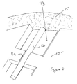
- Each second section 11b has inclined side walls, as shown in Figure 6.
- the panel 10 can be either 40 or 50 mm. in thickness, 2400 mm. in length and 1200 mm. in width.
- the channels 11 can be arranged at 150 mm., 200 mm., 250 mm. or 300 mm. centres. If the channels 11 are arranged at 200 mm. centres, the second sections 11b will typically have a maximum width within the range of from 75 to 100 mm. whereas, if the channels 11 are arranged at 300 mm. centres, the second sections 11b will typically have a maximum width of 100 to 200 mm. If the heating pipe 12 has an outside diameter of 19 mm., the first channel sections 11a will have a width of 18 mm.
- the heating pipe 12 has an outside diameter of 17 mm.
- the first channel sections will have a width of 16 mm.
- Foamed polystyrene has a degree of resilience such that, when the heating pipe 12 is fitted in the channels 11, the heating pipe 12 is held in position by engagement with the channel first sections 11a, without any requirement for a mesh or other fixing devices.
- the panel 10 is used in conjunction with panels 20 constructed as shown in Figure 7.
- the panel 20 is formed of foamed polystyrene and is of the same thickness as the panel 10. It is cut into three portions of equal size, and then trimmed as appropriate, so as to provide connectors for joining together the channels in a plurality of panels 10 in, for example, the manner illustrated in Figure 9.
- Each of the connectors includes a number of curvate channels or balloon ends 21, each of substantially the same width as the first channel sections 11a of the panels 10. The radius of the balloon ends can be adjusted to suit the minimum bending radius of the heating pipe 12.
- the screed mix can then be applied using wheelbarrows 22 which are wheeled over duckboards 23, as illustrated in Figure 12, without doing any damage to the heating pipe 12, as opposed to the arrangement shown in Figure 13, which has been used for the known method for the production of screeded floors as illustrated in Figures 1 and 1a.
- the screed 15 is a sand/cement mixture and is introduced, as shown in Figure 8, so that it covers the panel 10 and fills the second channel sections 11b.
- the screed 15 is then levelled and allowed to set.
- a typical screed 15 has a thickness above the upper surface of the panels 10 of between 65 and 75 mm. and, because there are no pipes or other fitments projecting into the thickness of the screed 15, fixings can confidently be drilled into the screed 15 and expansion gaps can be sawn in the screed 15.
- An alternative method of applying the screed involves pumping a very runny liquid over the assembled panels.
- the runny liquid has a self-levelling action and, if this type of screed is to be used, the panels of the underfloor heating system will be provided along their edges with interengaging tongue and groove formations to prevent the runny liquid from escaping through any gaps between adjacent panels.
- each pipe 12 radiates heat through the body of the screed 15 in a particularly efficient manner, with the sand/cement mixture in the second channel sections 11b acting as a heat diffuser.
- FIG. 14 A similar arrangement will be obtained with the floating floor underfloor heating system shown in Figure 14.
- the panel 10 is formed with a series of channels, one only of which is shown.
- Each channel includes a number of first sections 11a in which the heating pipe 12 is a close fit and a number of second sections 11b which are of substantially greater width than the diameter of the pipe 12.
- a sand/cement mixture 16 is introduced into each of the second channel sections 11b, so as to fill the space available within each second channel section 11b, i.e. the upper surface of the sand/cement mixture is flush with the upper surface of the panel 10.
- each channel section 11a, 11b is substantially the same as the diameter of the pipe 12.
- the channel sections 11a and 11b may have a depth of 20 mm.
- the sand/cement mixture is an inexpensive, readily available thermally conductive material, which acts as a heat diffuser. After the sand/cement mixture has set, the flooring 17 is laid on top of the panels 10 and typically comprises chipboard panels or planks having tongue and groove formations along their edges.
- the panels 10 shown in Figure 5 have second channel sections 11b which have planar end walls which extend vertically at right angles to the axis of the respective channel 11.
- This channel configuration is produced by first forming longitudinal channels having configurations corresponding to the first channel sections 11a in a panel 10 and then forming the second channel sections 11b by a cutting process using a heated wire of the appropriate shape.
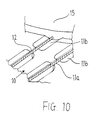
- the alternative panel construction shown in Figure 10 includes second channel sections 11b which are formed using a routing tool and accordingly have curvate end walls.
- the underfloor heating arrangement shown in Figure 9 is produced using panels 10 and 20. Additional panels which can be used in conjunction with the panels 10 are shown in Figures 15, 16 and 17.
- the panel 25 shown in Figure 15 is formed with a plurality of parallel channels 26 which are of the same spacing and configuration as the first channel sections 11a of panel 10.
- a panel 25 will be used in an area where, for any reason, less heat output is required.
- the panel 27 shown in Figure 16 is intended to be cut in half to form two separate panels, 27a and 27b, each of which contains a plurality of parallel curved channels 28 which receive the heating pipe 12 and enable the pipe 12 to be turned through angles up to and including 90°.
- the panel 29 shown in Figure 17 is intended to be cut in quarters to form four separate panels 29a, 29b, 29c and 29d.
- the panels 29a to 29d each contain a plurality of curved channels 30 which receive the heating pipe 12 and are used when it is desired to turn the pipe 12 through 90° and, at the same time, reduce the spacing between adjacent lengths of pipe. For example, such panels may be used when the heating pipes must be brought to the supply manifold.
- the heat output from this construction method is slightly lower than the output from one which uses aluminium heat diffusers but it is still sufficient to suit the heating requirements of a well-insulated new building which is built in accordance with modern building practice.
- the panel of the present invention makes installation of underfloor heating in a fully floating floor a simple and inexpensive operation. Rigid installation would be installed in such a floor construction in any event, even if a different non-underfloor heating system was to be used. There is very little additional cost associated with fitting the heating pipe and this does not need specialist labour.
- the panel of the present invention can be made inexpensively in large quantities in a factory. It is light in weight and thus easy to handle. The production cost savings arising from this further make it possible to reduce the cost of supplying and installing an underfloor heating system in a screeded floor or in a fully floating floor.
Landscapes
- Engineering & Computer Science (AREA)
- Physics & Mathematics (AREA)
- Thermal Sciences (AREA)
- Chemical & Material Sciences (AREA)
- Combustion & Propulsion (AREA)
- Mechanical Engineering (AREA)
- General Engineering & Computer Science (AREA)
- Steam Or Hot-Water Central Heating Systems (AREA)
- Floor Finish (AREA)
- Domestic Hot-Water Supply Systems And Details Of Heating Systems (AREA)
Abstract
Description
- This invention relates to underfloor heating panels and to methods of installing underfloor heating systems using such panels.
- The panel of the present invention has been developed to make it easier to install underfloor heating in floors which are constructed either as a screeded floor over insulation or as a timber floor deck which is fully supported on rigid insulation (normally referred to as a fully-floating floor).
- It is presently common practice to install warm water underfloor heating in a screeded floor using any one of the construction methods illustrated in Figures 1 and 1a, 2 and 2a, and 3 and 3a.
- Figures 1 and 1a show how rigid insulation panels (a) are covered with steel reinforcing mesh (b) and how the heating pipe (c) is tied to the top of the mesh. Screed (d) is then laid over the whole.
- Figures 2 and 2a show how rigid insulation panels (a) have heating pipe (c) fixed in place using staples (e) which catch into a fabric surface which is bonded to the top surface of the insulation. Screed (d) is then again laid over the whole assemblage.
- Figures 3 and 3a show how rigid insulation panels (a) have fixing rails (f) attached and how the heating pipe (c) is held in place by them. Screed (d) is then laid over the whole assemblage.
- It is also common practice to install warm water underfloor heating in a fully floating floor using grooved rigid insulation and rigid aluminium heat diffuser plates. Figures 4, 4a and 4b show rigid insulation (a) with heat diffuser plates (g) and heating pipe (c) beneath a timber floor deck (h). The diffuser plates (g) are typically formed from hard-temper aluminium sheets 0.4 to 0.7 mm. thick and they have channels to accept the heating pipe. The width of the channels corresponds to the outside diameter of the heating pipe (c).
- Figures 4, 4a and 4b show a configuration having two channels per plate, but it is also common to have a single channel per plate when a plate must be used with larger diameter pipe. The diffuser plates (g) are set on top of the grooved insulation (a) in such a way that each preformed diffuser plate (g) engages with the channels formed in the top of the insulation (a). The heating pipe (c) is pressed into the channels in the diffuser plate (g) which then acts as a fin to the pipe (c), conducting the heat away from the pipe (c) and spreading it evenly across the underside of the floor deck. The floor deck is typically chipboard, plywood, cement-bonded particle board or timber planks.
- The heat output from any of these forms of construction is quite satisfactory and they are widely used but they have a number of disadvantages. Those for screeded floors are as follows:
- 1) In all three of the cases illustrated in Figures 1 to 3, the heating pipe (c) sits on top of the insulation (a). The specialists who lay the screed surface must transport the screed - generally in wheelbarrows - across the floor and thus across the top of the exposed pipe (c). As a consequence, the heating pipe (c) is very susceptible to damage before the heating system has even been brought into use,
- 2) In all three cases, the pipe is installed within the thickness of the screed and yet, with the screed in place, there is no simple way of knowing where the pipe has been set or at what depth. Fixings cannot be confidently drilled into the screed. Expansion gaps cannot be confidently sawn into the screed across its width. The problem is most acute with the most commonly used, pipe-on-mesh installation method shown in Figures 1 and 1a, because the mesh is often not flat and the pipe can be at any depth within the screed.
- 3) With the pipe-on-mesh method shown in Figures 1 and 1a, the mesh itself usually has 4 to 6 mm. bars. These can only be cut using an angle grinder, and this introduces Health and Safety issues. The cut ends of the bars are supposed to be wired together to stop them catching ankles or feet, and this is time-consuming.
- 4) In all three cases, the heat output from the floor varies according to the spacing of the pipe and, in each case, the actual installed pipe spacing is dependent on the skill and accuracy of the installer. It is difficult to achieve consistent quality of installation across a range of building sites using different installers.
- 5) In all three cases, the labour cost of installation is high.
-
- Current methods of installing underfloor heating systems in floating floors also have a number of disadvantages, as follows:-
- 1) The heating system is formed on site as an assembly of pipe, diffuser plates and insulation which have to be cut to length and installed by skilled installers.
- 2) Installation is labour-intensive and costly.
- 3)The diffuser plates are themselves expensive.
- 4) The cutting of the diffuser plates in particular must be done with great care by hand using tin shears. Jagged edges can be left which can damage the heating pipe.
- 5) The diffuser plates have to be rigid and strong enough to withstand handling on site and to prevent them being damaged too easily. Despite being from 0.4 to 0.7 mm. in thickness, they are still prone to being bent and are subject to wind damage when being unloaded or moved around a site.
- 6) The strength and rigidity of the diffuser plates makes them noisy in use. The aluminium itself expands and contracts much more than the timber floor deck with which it is in close contact and, as a consequence, differential creep occurs at the boundary between the plate and the floor deck during warm up and cool down, and this creates creaking sounds which users complain about.
-
- It is an object of the present invention to provide an underfloor heating panel and a method of installing an underfloor heating system which address these shortcomings.
- According to a first aspect of the present invention there is provided an underfloor heating panel which is formed with a channel in which a heating pipe is received, the channel including at least one first section in which the heating pipe is a close fit and at least one second section which is wider than the or each first section, thermally conductive material being introduced into said at least one second section in use of the panel to provide an underfloor heating system.
- The panel is preferably formed with a plurality of parallel channels each of which includes a plurality of first sections and a plurality of second sections.
- According to a second aspect of the present invention there is provided a method of installing an underfloor heating system which includes providing at least one underfloor heating panel as defined above, inserting a heating pipe in the channel so that it is held in the channel as a result of its close fit in said at least one first section of the channel, and introducing a thermally conductive material into the at least one second section of the channel.
- The term "heating pipe" as used herein includes a pipe through which hot water can be passed and a cable which contains an electrical heating element.
- Each panel is preferably formed of a foamed or expanded synthetic plastics material, such as foamed polystyrene, and the channel second sections may be formed using, for example, either a router or a heated wire.
- The installation of an underfloor heating system preferably includes the use of a plurality of panels as defined above in conjunction with other flooring panels which have pipe channels of constant width, the same as the pipe outside diameter, so that the heating pipe is a close fit in the channels of said other panels.
- As applied to a screeded floor, the thermally conductive material introduced into the second sections of the channels is preferably the screed material. As applied to a fully floating floor, the thermally conductive material introduced into the second sections of the channels is preferably a sand/cement mix, the amount of which is such that its upper surface is flush with the upper surface of the associated panel.
-
- Figures 1 and 1a illustrate a current method of installing warm water underfloor heating in a screeded floor,
- Figures 2 and 2a illustrate another current method of installing warm water underfloor heating in a screeded floor,
- Figures 3 and 3a illustrate a further method of installing warm water underfloor heating in a screeded floor,
- Figures 4, 4a and 4b illustrate a current method of installing warm water underfloor heating in a fully floating floor,
- Figure 5 is a plan view of the panel of the present invention,
- Figure 6 is a sectional view of the panel of Figure 5, along the line 6 - 6 of Figure 5,
- Figure 7 is a plan view of an insulating panel for use with the panel of Figure 5,
- Figure 8 shows a stage in the installation of the panel of Figure 5 in a screeded floor,
- Figure 9 shows an assembly of panels,
- Figure 10 shows a modified form of panel in accordance with the present invention,
- Figure 11 shows the pattern of heat distribution in a screeded floor,
- Figure 12 shows the use of a wheelbarrow in the transport of a sand/cement mixture when producing a screeded floor using panels as shown in Figure 5,
- Figure 13 shows the use of a wheelbarrow in the transport of a sand/cement mixture when producing a screeded floor using the pipe on mesh method shown in Figures 1 and 1a,
- Figure 14 shows application of the panel of Figure 5 in a fully floating timber floor, and
- Figures 15, 16 and 17 are plan views of additional panels for use in conjunction with the panels of the present invention.
-
- The
panel 10 shown in Figure 5 is a panel of rigid insulation, particularly foamed polystyrene, which has a plurality of channels 11 formed in its top surface. Each channel 11 includes a number offirst sections 11a of a width which is slightly less than the outside diameter of aheating pipe 12 and a plurality ofsecond sections 11b of a width which is considerably greater than the diameter of thepipe 12. Eachsecond section 11b has inclined side walls, as shown in Figure 6. - For example, the
panel 10 can be either 40 or 50 mm. in thickness, 2400 mm. in length and 1200 mm. in width. The channels 11 can be arranged at 150 mm., 200 mm., 250 mm. or 300 mm. centres. If the channels 11 are arranged at 200 mm. centres, thesecond sections 11b will typically have a maximum width within the range of from 75 to 100 mm. whereas, if the channels 11 are arranged at 300 mm. centres, thesecond sections 11b will typically have a maximum width of 100 to 200 mm. If theheating pipe 12 has an outside diameter of 19 mm., thefirst channel sections 11a will have a width of 18 mm. whereas, if theheating pipe 12 has an outside diameter of 17 mm., the first channel sections will have a width of 16 mm. Foamed polystyrene has a degree of resilience such that, when theheating pipe 12 is fitted in the channels 11, theheating pipe 12 is held in position by engagement with the channelfirst sections 11a, without any requirement for a mesh or other fixing devices. - In installation of an underfloor heating system, the
panel 10 is used in conjunction withpanels 20 constructed as shown in Figure 7. Thepanel 20 is formed of foamed polystyrene and is of the same thickness as thepanel 10. It is cut into three portions of equal size, and then trimmed as appropriate, so as to provide connectors for joining together the channels in a plurality ofpanels 10 in, for example, the manner illustrated in Figure 9. Each of the connectors includes a number of curvate channels or balloon ends 21, each of substantially the same width as thefirst channel sections 11a of thepanels 10. The radius of the balloon ends can be adjusted to suit the minimum bending radius of theheating pipe 12. - In the particular arrangement shown in Figure 9, six
panels 10, each constructed as shown in Figure 5, are placed in position, and connectors formed frompanels 20 are then positioned, as shown, so that thecurvate channels 21 register with the ends of the channels 11. Once the assembly ofpanels 10 and connectors has been completed, theheating pipe 12, which is typically a thin-walled flexible plastic tube, is pressed into place in thechannels 11 and 21, being held in position by being a push fit in thefirst channel sections 11a and thechannels 21. - After the
heating pipe 12 has been pressed into thechannels 11 and 21, and any connections to theheating pipe 12 have been made, the screed mix can then be applied usingwheelbarrows 22 which are wheeled overduckboards 23, as illustrated in Figure 12, without doing any damage to theheating pipe 12, as opposed to the arrangement shown in Figure 13, which has been used for the known method for the production of screeded floors as illustrated in Figures 1 and 1a. Thescreed 15 is a sand/cement mixture and is introduced, as shown in Figure 8, so that it covers thepanel 10 and fills thesecond channel sections 11b. Thescreed 15 is then levelled and allowed to set. Atypical screed 15 has a thickness above the upper surface of thepanels 10 of between 65 and 75 mm. and, because there are no pipes or other fitments projecting into the thickness of thescreed 15, fixings can confidently be drilled into thescreed 15 and expansion gaps can be sawn in thescreed 15. - An alternative method of applying the screed involves pumping a very runny liquid over the assembled panels. The runny liquid has a self-levelling action and, if this type of screed is to be used, the panels of the underfloor heating system will be provided along their edges with interengaging tongue and groove formations to prevent the runny liquid from escaping through any gaps between adjacent panels.
- A heat distribution pattern as shown in Figure 11 is obtained. Thus, each
pipe 12 radiates heat through the body of thescreed 15 in a particularly efficient manner, with the sand/cement mixture in thesecond channel sections 11b acting as a heat diffuser. - A similar arrangement will be obtained with the floating floor underfloor heating system shown in Figure 14. This includes a series of
panels 10, one only of which is shown in Figure 14. Thepanel 10 is formed with a series of channels, one only of which is shown. Each channel includes a number offirst sections 11a in which theheating pipe 12 is a close fit and a number ofsecond sections 11b which are of substantially greater width than the diameter of thepipe 12. After thepipe 12 has been inserted in the channels so as to be gripped by thefirst channel sections 11a, a sand/cement mixture 16 is introduced into each of thesecond channel sections 11b, so as to fill the space available within eachsecond channel section 11b, i.e. the upper surface of the sand/cement mixture is flush with the upper surface of thepanel 10. As can be seen from Figure 14, the depth of eachchannel section pipe 12. Thus, for apanel 10 intended to be used in conjunction with apipe 12 having an external diameter of 19 mm., thechannel sections panels 10 and typically comprises chipboard panels or planks having tongue and groove formations along their edges. - The
panels 10 shown in Figure 5 havesecond channel sections 11b which have planar end walls which extend vertically at right angles to the axis of the respective channel 11. This channel configuration is produced by first forming longitudinal channels having configurations corresponding to thefirst channel sections 11a in apanel 10 and then forming thesecond channel sections 11b by a cutting process using a heated wire of the appropriate shape. The alternative panel construction shown in Figure 10 includessecond channel sections 11b which are formed using a routing tool and accordingly have curvate end walls. - The underfloor heating arrangement shown in Figure 9 is produced using
panels panels 10 are shown in Figures 15, 16 and 17. - The
panel 25 shown in Figure 15 is formed with a plurality ofparallel channels 26 which are of the same spacing and configuration as thefirst channel sections 11a ofpanel 10. Apanel 25 will be used in an area where, for any reason, less heat output is required. - The
panel 27 shown in Figure 16 is intended to be cut in half to form two separate panels, 27a and 27b, each of which contains a plurality of parallel curved channels 28 which receive theheating pipe 12 and enable thepipe 12 to be turned through angles up to and including 90°. - The
panel 29 shown in Figure 17 is intended to be cut in quarters to form fourseparate panels 29a, 29b, 29c and 29d. The panels 29a to 29d each contain a plurality ofcurved channels 30 which receive theheating pipe 12 and are used when it is desired to turn thepipe 12 through 90° and, at the same time, reduce the spacing between adjacent lengths of pipe. For example, such panels may be used when the heating pipes must be brought to the supply manifold. - Use of the panel of the present invention in the installation of an underfloor heating system offers the following advantages over current practice in relation to screeded floors:-
- a) The heating pipe sits entirely within the thickness of the insulation and is protected by it. As a consequence, when the pipe is installed, it becomes possible to lay duckboards across the insulation and to transport the screed around the room without risk of damaging the pipe. [See Figures 12 and 13].
- b) The channels in which the pipe are located are formed at set spacings. This provides assured heat output and eliminates any dependency on the skill and experience of the installer to achieve the correct pipe spacing.
- c) The screed is in sufficient contact with the heating pipe that the difference in heating performance, when compared with current systems having the heating pipe on top of the insulation, is negligible.
- d) Use of the panel of the present invention avoids the cost of steel mesh, or the cost of the special insulation which is need to work with staple fixings and the cost of the staples, or the cost of the special fixing rails.
- e) Installation of the insulation and the pipe can be undertaken by unskilled site labour and yet it can allow repeatable installation quality to be achieved.
- f) With the pipe wholly below the top of the insulation, fixings can be drilled into any part of the depth of the screed and/or expansion gaps can be cut across any part of the screed.
-
- In respect of current practice as applied to fully floating floors, use of the panel of the present invention offers the following advantages over current practice:
- a) it avoids the need for expensive, rigid aluminium diffuser plates and the creaking during warming up and cooling down which these can cause,
- b) the spacing of the heating pipe is automatically accurately determined by the spacings of the channels in the insulation and this determines the heat output. In this way, a heating panel can be made which provides an assured heat output and consistent installation quality which is not dependent on the skill or accuracy of the installer,
- c) the panels can be positioned by an unskilled installer and there is no need for specialist installers to be used,
- d) fitting of the heating pipe on site is reduced to a simple procedure of pressing the pipe into the channel in the insulation and this does not require specialist installers, and
- e) formation of a heating system on site by specialist installers using separate pipes, insulation and diffuser plates is replaced by the simple installation of standard panels.
-
- The heat output from this construction method is slightly lower than the output from one which uses aluminium heat diffusers but it is still sufficient to suit the heating requirements of a well-insulated new building which is built in accordance with modern building practice.
- The panel of the present invention makes installation of underfloor heating in a fully floating floor a simple and inexpensive operation. Rigid installation would be installed in such a floor construction in any event, even if a different non-underfloor heating system was to be used. There is very little additional cost associated with fitting the heating pipe and this does not need specialist labour.
- The panel of the present invention can be made inexpensively in large quantities in a factory. It is light in weight and thus easy to handle. The production cost savings arising from this further make it possible to reduce the cost of supplying and installing an underfloor heating system in a screeded floor or in a fully floating floor.
Claims (10)
- An underfloor heating panel (10) which is formed with a channel (11) in which a heating pipe (12) is received, the channel (11) including at least one first section (11a) in which the heating pipe is a close fit and at least one second section (11b) which is wider than the or each first section (11a), thermally conductive material being introduced into said at least one second section (11b) in use of the panel (10) to provide an underfloor heating system.
- A panel is claimed in Claim 1, which is formed with a plurality of channels (11) each of which includes a plurality of first and/or second sections (11a and/or 11b).
- A panel as claimed in Claim 2, in which the channels (11) are parallel and in which each channel (11) includes a plurality of first sections (11 a) and a plurality of second channels (11b).
- A panel as claimed in Claim 2, which is formed of foamed polystyrene and in which the or each channel (11) is formed using a routing cutter and/or a heated wire.
- A method of installing an underfloor heating system which includes providing at least one underfloor heating panel (10) as claimed in Claim 1, inserting a heating pipe (12) in the channel (11) so that it is held in the channel (11) as a result of its close fit in said at least one first section (11a) of the channel (11), and introducing a thermally conductive material into the at least one second section (11b) of the channel (11).
- A method of installing an underfloor heating system which includes providing a plurality of underfloor heating panels (10), each as claimed in any one of Claims 2 to 4, assembling the panels (10) so that the channels (11) in the panels (10) communicate with one another and/or with channels (26, 28, 30) formed in connector panels (25, 27, 29), inserting a heating pipe (12) in the communicating channels so that it is held as a close fit in said first sections (11a) of the channels (11), and introducing a thermally conductive material into the second sections (11b) of the channels (11).
- A method as claimed in Claim 6, as applied to a screeded floor, in which the thermally conductive material introduced into the second sections (11b) of the channels (11) is the screed material (15).
- A method as claimed in Claim 6, as applied to a fully floating floor, in which the thermally conductive material introduced into the second sections (11b) of the channels (11) is a sand/cement mix.
- A method as claimed in Claim 8, in which the amount of sand/cement mix introduced into the second sections (11b) of the channels (11) is such that its upper surface is flush with the upper surface of the associated panel (10).
- A method as claimed in Claim 7, in which the panels (10) are provided with tongue and groove formations along their edges.
Applications Claiming Priority (2)
| Application Number | Priority Date | Filing Date | Title |
|---|---|---|---|
| GBGB9824083.1A GB9824083D0 (en) | 1998-11-05 | 1998-11-05 | Underfloor heating panels |
| GB9824083 | 1998-11-05 |
Publications (2)
| Publication Number | Publication Date |
|---|---|
| EP0999415A2 true EP0999415A2 (en) | 2000-05-10 |
| EP0999415A3 EP0999415A3 (en) | 2002-08-21 |
Family
ID=10841783
Family Applications (1)
| Application Number | Title | Priority Date | Filing Date |
|---|---|---|---|
| EP99308771A Withdrawn EP0999415A3 (en) | 1998-11-05 | 1999-11-04 | Underfloor heating panels |
Country Status (2)
| Country | Link |
|---|---|
| EP (1) | EP0999415A3 (en) |
| GB (2) | GB9824083D0 (en) |
Families Citing this family (3)
| Publication number | Priority date | Publication date | Assignee | Title |
|---|---|---|---|---|
| GB2426317B (en) * | 2005-05-18 | 2007-10-17 | Siemens Magnet Technology Ltd | A superconducting magnet structure having a former cooled by a thermally conductive tube retained within a channel formed in the former |
| GB2473259A (en) * | 2009-09-07 | 2011-03-09 | Nicholas Julian Jan Francis Macphail | Underfloor heating panel having heating pipe channels of variable width |
| US9404690B2 (en) * | 2011-08-03 | 2016-08-02 | Haier US Applicance Solutions, Inc. | Condenser coil holder for water heater |
Citations (3)
| Publication number | Priority date | Publication date | Assignee | Title |
|---|---|---|---|---|
| EP0039446A1 (en) * | 1980-04-24 | 1981-11-11 | Jiri Elias | Structure for embedded radiant room heating |
| US4588125A (en) * | 1983-01-11 | 1986-05-13 | Hans Lutz | Liquid surface heating system for floors |
| WO1991000488A1 (en) * | 1989-06-27 | 1991-01-10 | Bengt Valdemar Eggemar | Method and apparatus for heat exchange, where channels, e.g. tubes, are secured in recesses in heat-isolating boards |
-
1998
- 1998-11-05 GB GBGB9824083.1A patent/GB9824083D0/en not_active Ceased
-
1999
- 1999-11-04 GB GB9926033A patent/GB2343506B/en not_active Expired - Fee Related
- 1999-11-04 EP EP99308771A patent/EP0999415A3/en not_active Withdrawn
Patent Citations (3)
| Publication number | Priority date | Publication date | Assignee | Title |
|---|---|---|---|---|
| EP0039446A1 (en) * | 1980-04-24 | 1981-11-11 | Jiri Elias | Structure for embedded radiant room heating |
| US4588125A (en) * | 1983-01-11 | 1986-05-13 | Hans Lutz | Liquid surface heating system for floors |
| WO1991000488A1 (en) * | 1989-06-27 | 1991-01-10 | Bengt Valdemar Eggemar | Method and apparatus for heat exchange, where channels, e.g. tubes, are secured in recesses in heat-isolating boards |
Also Published As
| Publication number | Publication date |
|---|---|
| GB2343506B (en) | 2003-05-14 |
| GB2343506A (en) | 2000-05-10 |
| GB9926033D0 (en) | 2000-01-12 |
| EP0999415A3 (en) | 2002-08-21 |
| GB9824083D0 (en) | 1998-12-30 |
Similar Documents
| Publication | Publication Date | Title |
|---|---|---|
| US6283382B1 (en) | Radiant heating system pipe mounting plate | |
| US5788152A (en) | Floor heating system | |
| US8020783B2 (en) | Radiant mat grid | |
| CA2639591C (en) | Heating wire support meshing and method of constructing a heated surface with same | |
| US6621983B2 (en) | Floor heating device with self-regulating cable | |
| US6009612A (en) | Apparatus for attaching radiating plate to holders of modular unit for radiant floor and wall hydronic heating systems | |
| JP2007107876A (en) | Floor heating system | |
| EP1055087B1 (en) | Floor heating device with self-regulating cable | |
| EP0999415A2 (en) | Underfloor heating panels | |
| EP1353129A1 (en) | Overfloor heating system | |
| EP2148142B1 (en) | Device for holding a pipe in a groove of a temperature control system integrated in a surface and method therefor | |
| EP0999416A2 (en) | Method of installing underfloor heating panels | |
| CA2070456C (en) | Heated floor | |
| US11490462B2 (en) | Grooved floor underlayment for radiant heat | |
| EP0943873A1 (en) | Apparatus and method of attaching radiating plate to holders of modular unit for radiant floor and wall hydronic heating systems | |
| GB2460420A (en) | Heat transfer panel with reinforcing layer | |
| JPH0718558B2 (en) | Wood-based hot water floor heating panel and its construction method | |
| EP4098949A1 (en) | Method for forming a construction panel | |
| JPH08319712A (en) | Floor heating structure | |
| EP0959306A2 (en) | Heated floor for buildings | |
| JPH0821074A (en) | Bed panel, heating device, floor heating floor, and constructing method | |
| GB2467962A (en) | Panel for use with a heating/cooling system | |
| WO1983000056A1 (en) | Floor panel | |
| GB2589105A (en) | A thermal insulation and diffusion floor panel for an underfloor heating or cooling system | |
| AU701134B2 (en) | Floor heating system |
Legal Events
| Date | Code | Title | Description |
|---|---|---|---|
| PUAI | Public reference made under article 153(3) epc to a published international application that has entered the european phase |
Free format text: ORIGINAL CODE: 0009012 |
|
| AK | Designated contracting states |
Kind code of ref document: A2 Designated state(s): AT BE CH CY DE DK ES FI FR GB GR IE IT LI LU MC NL PT SE |
|
| AX | Request for extension of the european patent |
Free format text: AL;LT;LV;MK;RO;SI |
|
| PUAL | Search report despatched |
Free format text: ORIGINAL CODE: 0009013 |
|
| AK | Designated contracting states |
Kind code of ref document: A3 Designated state(s): AT BE CH CY DE DK ES FI FR GB GR IE IT LI LU MC NL PT SE |
|
| AX | Request for extension of the european patent |
Free format text: AL;LT;LV;MK;RO;SI |
|
| STAA | Information on the status of an ep patent application or granted ep patent |
Free format text: STATUS: THE APPLICATION IS DEEMED TO BE WITHDRAWN |
|
| 18D | Application deemed to be withdrawn |
Effective date: 20020601 |