EP0999290B1 - Wear-resistant coated member - Google Patents
Wear-resistant coated member Download PDFInfo
- Publication number
- EP0999290B1 EP0999290B1 EP99108517A EP99108517A EP0999290B1 EP 0999290 B1 EP0999290 B1 EP 0999290B1 EP 99108517 A EP99108517 A EP 99108517A EP 99108517 A EP99108517 A EP 99108517A EP 0999290 B1 EP0999290 B1 EP 0999290B1
- Authority
- EP
- European Patent Office
- Prior art keywords
- layer
- none
- nos
- composition
- hard coating
- Prior art date
- Legal status (The legal status is an assumption and is not a legal conclusion. Google has not performed a legal analysis and makes no representation as to the accuracy of the status listed.)
- Expired - Lifetime
Links
- 239000000203 mixture Substances 0.000 claims abstract description 126
- 238000000576 coating method Methods 0.000 claims abstract description 101
- 239000011248 coating agent Substances 0.000 claims abstract description 95
- 230000003014 reinforcing effect Effects 0.000 claims abstract description 24
- 229910052751 metal Inorganic materials 0.000 claims description 31
- 239000002184 metal Substances 0.000 claims description 29
- 150000002739 metals Chemical class 0.000 claims description 19
- 239000010410 layer Substances 0.000 description 206
- 239000010936 titanium Substances 0.000 description 137
- 238000005520 cutting process Methods 0.000 description 55
- ATJFFYVFTNAWJD-UHFFFAOYSA-N Tin Chemical compound [Sn] ATJFFYVFTNAWJD-UHFFFAOYSA-N 0.000 description 47
- 239000000758 substrate Substances 0.000 description 40
- 229910052782 aluminium Inorganic materials 0.000 description 37
- 229910052719 titanium Inorganic materials 0.000 description 35
- 229910052720 vanadium Inorganic materials 0.000 description 29
- 239000000463 material Substances 0.000 description 27
- 229910052799 carbon Inorganic materials 0.000 description 19
- 230000000052 comparative effect Effects 0.000 description 19
- HDKLIZDXVUCLHQ-UHFFFAOYSA-N non-3-en-2-one Chemical compound CCCCCC=CC(C)=O HDKLIZDXVUCLHQ-UHFFFAOYSA-N 0.000 description 12
- 229910045601 alloy Inorganic materials 0.000 description 8
- 239000000956 alloy Substances 0.000 description 8
- 230000015572 biosynthetic process Effects 0.000 description 8
- 239000011247 coating layer Substances 0.000 description 6
- 230000008018 melting Effects 0.000 description 6
- 238000002844 melting Methods 0.000 description 6
- 229910052804 chromium Inorganic materials 0.000 description 5
- 229910052735 hafnium Inorganic materials 0.000 description 5
- 238000000034 method Methods 0.000 description 5
- 229910052750 molybdenum Inorganic materials 0.000 description 5
- 229910052758 niobium Inorganic materials 0.000 description 5
- 102220005308 rs33960931 Human genes 0.000 description 5
- 229910052715 tantalum Inorganic materials 0.000 description 5
- 229910000831 Steel Inorganic materials 0.000 description 4
- 239000002131 composite material Substances 0.000 description 4
- 238000007733 ion plating Methods 0.000 description 4
- JMANVNJQNLATNU-UHFFFAOYSA-N oxalonitrile Chemical compound N#CC#N JMANVNJQNLATNU-UHFFFAOYSA-N 0.000 description 4
- 239000010959 steel Substances 0.000 description 4
- 229910052721 tungsten Inorganic materials 0.000 description 4
- 229910000760 Hardened steel Inorganic materials 0.000 description 3
- 229910000997 High-speed steel Inorganic materials 0.000 description 3
- 230000000694 effects Effects 0.000 description 3
- 238000010891 electric arc Methods 0.000 description 3
- 238000003801 milling Methods 0.000 description 3
- 229910052726 zirconium Inorganic materials 0.000 description 3
- 229910000975 Carbon steel Inorganic materials 0.000 description 2
- FAPWRFPIFSIZLT-UHFFFAOYSA-M Sodium chloride Chemical compound [Na+].[Cl-] FAPWRFPIFSIZLT-UHFFFAOYSA-M 0.000 description 2
- 125000004429 atom Chemical group 0.000 description 2
- 239000010962 carbon steel Substances 0.000 description 2
- 239000000919 ceramic Substances 0.000 description 2
- 230000007423 decrease Effects 0.000 description 2
- 238000009792 diffusion process Methods 0.000 description 2
- 238000005553 drilling Methods 0.000 description 2
- 238000001035 drying Methods 0.000 description 2
- 230000008020 evaporation Effects 0.000 description 2
- 238000001704 evaporation Methods 0.000 description 2
- 150000001247 metal acetylides Chemical class 0.000 description 2
- 238000012986 modification Methods 0.000 description 2
- 230000004048 modification Effects 0.000 description 2
- 102220259718 rs34120878 Human genes 0.000 description 2
- -1 (Al Substances 0.000 description 1
- 229910017150 AlTi Inorganic materials 0.000 description 1
- RTAQQCXQSZGOHL-UHFFFAOYSA-N Titanium Chemical compound [Ti] RTAQQCXQSZGOHL-UHFFFAOYSA-N 0.000 description 1
- 238000010521 absorption reaction Methods 0.000 description 1
- 239000000853 adhesive Substances 0.000 description 1
- 230000001070 adhesive effect Effects 0.000 description 1
- 125000004432 carbon atom Chemical group C* 0.000 description 1
- 239000011195 cermet Substances 0.000 description 1
- 230000008859 change Effects 0.000 description 1
- 238000005260 corrosion Methods 0.000 description 1
- 239000013078 crystal Substances 0.000 description 1
- 238000004453 electron probe microanalysis Methods 0.000 description 1
- 239000000839 emulsion Substances 0.000 description 1
- 230000001771 impaired effect Effects 0.000 description 1
- 239000000314 lubricant Substances 0.000 description 1
- 238000005259 measurement Methods 0.000 description 1
- 150000004767 nitrides Chemical class 0.000 description 1
- 125000004433 nitrogen atom Chemical group N* 0.000 description 1
- 230000003287 optical effect Effects 0.000 description 1
- 239000011219 quaternary composite Substances 0.000 description 1
- 230000009257 reactivity Effects 0.000 description 1
- 238000000682 scanning probe acoustic microscopy Methods 0.000 description 1
- 239000011780 sodium chloride Substances 0.000 description 1
Classifications
-
- B—PERFORMING OPERATIONS; TRANSPORTING
- B32—LAYERED PRODUCTS
- B32B—LAYERED PRODUCTS, i.e. PRODUCTS BUILT-UP OF STRATA OF FLAT OR NON-FLAT, e.g. CELLULAR OR HONEYCOMB, FORM
- B32B15/00—Layered products comprising a layer of metal
- B32B15/04—Layered products comprising a layer of metal comprising metal as the main or only constituent of a layer, which is next to another layer of the same or of a different material
-
- C—CHEMISTRY; METALLURGY
- C23—COATING METALLIC MATERIAL; COATING MATERIAL WITH METALLIC MATERIAL; CHEMICAL SURFACE TREATMENT; DIFFUSION TREATMENT OF METALLIC MATERIAL; COATING BY VACUUM EVAPORATION, BY SPUTTERING, BY ION IMPLANTATION OR BY CHEMICAL VAPOUR DEPOSITION, IN GENERAL; INHIBITING CORROSION OF METALLIC MATERIAL OR INCRUSTATION IN GENERAL
- C23C—COATING METALLIC MATERIAL; COATING MATERIAL WITH METALLIC MATERIAL; SURFACE TREATMENT OF METALLIC MATERIAL BY DIFFUSION INTO THE SURFACE, BY CHEMICAL CONVERSION OR SUBSTITUTION; COATING BY VACUUM EVAPORATION, BY SPUTTERING, BY ION IMPLANTATION OR BY CHEMICAL VAPOUR DEPOSITION, IN GENERAL
- C23C28/00—Coating for obtaining at least two superposed coatings either by methods not provided for in a single one of groups C23C2/00 - C23C26/00 or by combinations of methods provided for in subclasses C23C and C25C or C25D
- C23C28/30—Coatings combining at least one metallic layer and at least one inorganic non-metallic layer
- C23C28/32—Coatings combining at least one metallic layer and at least one inorganic non-metallic layer including at least one pure metallic layer
- C23C28/321—Coatings combining at least one metallic layer and at least one inorganic non-metallic layer including at least one pure metallic layer with at least one metal alloy layer
-
- C—CHEMISTRY; METALLURGY
- C23—COATING METALLIC MATERIAL; COATING MATERIAL WITH METALLIC MATERIAL; CHEMICAL SURFACE TREATMENT; DIFFUSION TREATMENT OF METALLIC MATERIAL; COATING BY VACUUM EVAPORATION, BY SPUTTERING, BY ION IMPLANTATION OR BY CHEMICAL VAPOUR DEPOSITION, IN GENERAL; INHIBITING CORROSION OF METALLIC MATERIAL OR INCRUSTATION IN GENERAL
- C23C—COATING METALLIC MATERIAL; COATING MATERIAL WITH METALLIC MATERIAL; SURFACE TREATMENT OF METALLIC MATERIAL BY DIFFUSION INTO THE SURFACE, BY CHEMICAL CONVERSION OR SUBSTITUTION; COATING BY VACUUM EVAPORATION, BY SPUTTERING, BY ION IMPLANTATION OR BY CHEMICAL VAPOUR DEPOSITION, IN GENERAL
- C23C14/00—Coating by vacuum evaporation, by sputtering or by ion implantation of the coating forming material
- C23C14/02—Pretreatment of the material to be coated
- C23C14/024—Deposition of sublayers, e.g. to promote adhesion of the coating
-
- C—CHEMISTRY; METALLURGY
- C23—COATING METALLIC MATERIAL; COATING MATERIAL WITH METALLIC MATERIAL; CHEMICAL SURFACE TREATMENT; DIFFUSION TREATMENT OF METALLIC MATERIAL; COATING BY VACUUM EVAPORATION, BY SPUTTERING, BY ION IMPLANTATION OR BY CHEMICAL VAPOUR DEPOSITION, IN GENERAL; INHIBITING CORROSION OF METALLIC MATERIAL OR INCRUSTATION IN GENERAL
- C23C—COATING METALLIC MATERIAL; COATING MATERIAL WITH METALLIC MATERIAL; SURFACE TREATMENT OF METALLIC MATERIAL BY DIFFUSION INTO THE SURFACE, BY CHEMICAL CONVERSION OR SUBSTITUTION; COATING BY VACUUM EVAPORATION, BY SPUTTERING, BY ION IMPLANTATION OR BY CHEMICAL VAPOUR DEPOSITION, IN GENERAL
- C23C14/00—Coating by vacuum evaporation, by sputtering or by ion implantation of the coating forming material
- C23C14/06—Coating by vacuum evaporation, by sputtering or by ion implantation of the coating forming material characterised by the coating material
- C23C14/0641—Nitrides
-
- C—CHEMISTRY; METALLURGY
- C23—COATING METALLIC MATERIAL; COATING MATERIAL WITH METALLIC MATERIAL; CHEMICAL SURFACE TREATMENT; DIFFUSION TREATMENT OF METALLIC MATERIAL; COATING BY VACUUM EVAPORATION, BY SPUTTERING, BY ION IMPLANTATION OR BY CHEMICAL VAPOUR DEPOSITION, IN GENERAL; INHIBITING CORROSION OF METALLIC MATERIAL OR INCRUSTATION IN GENERAL
- C23C—COATING METALLIC MATERIAL; COATING MATERIAL WITH METALLIC MATERIAL; SURFACE TREATMENT OF METALLIC MATERIAL BY DIFFUSION INTO THE SURFACE, BY CHEMICAL CONVERSION OR SUBSTITUTION; COATING BY VACUUM EVAPORATION, BY SPUTTERING, BY ION IMPLANTATION OR BY CHEMICAL VAPOUR DEPOSITION, IN GENERAL
- C23C14/00—Coating by vacuum evaporation, by sputtering or by ion implantation of the coating forming material
- C23C14/06—Coating by vacuum evaporation, by sputtering or by ion implantation of the coating forming material characterised by the coating material
- C23C14/0664—Carbonitrides
-
- C—CHEMISTRY; METALLURGY
- C23—COATING METALLIC MATERIAL; COATING MATERIAL WITH METALLIC MATERIAL; CHEMICAL SURFACE TREATMENT; DIFFUSION TREATMENT OF METALLIC MATERIAL; COATING BY VACUUM EVAPORATION, BY SPUTTERING, BY ION IMPLANTATION OR BY CHEMICAL VAPOUR DEPOSITION, IN GENERAL; INHIBITING CORROSION OF METALLIC MATERIAL OR INCRUSTATION IN GENERAL
- C23C—COATING METALLIC MATERIAL; COATING MATERIAL WITH METALLIC MATERIAL; SURFACE TREATMENT OF METALLIC MATERIAL BY DIFFUSION INTO THE SURFACE, BY CHEMICAL CONVERSION OR SUBSTITUTION; COATING BY VACUUM EVAPORATION, BY SPUTTERING, BY ION IMPLANTATION OR BY CHEMICAL VAPOUR DEPOSITION, IN GENERAL
- C23C28/00—Coating for obtaining at least two superposed coatings either by methods not provided for in a single one of groups C23C2/00 - C23C26/00 or by combinations of methods provided for in subclasses C23C and C25C or C25D
- C23C28/04—Coating for obtaining at least two superposed coatings either by methods not provided for in a single one of groups C23C2/00 - C23C26/00 or by combinations of methods provided for in subclasses C23C and C25C or C25D only coatings of inorganic non-metallic material
- C23C28/044—Coating for obtaining at least two superposed coatings either by methods not provided for in a single one of groups C23C2/00 - C23C26/00 or by combinations of methods provided for in subclasses C23C and C25C or C25D only coatings of inorganic non-metallic material coatings specially adapted for cutting tools or wear applications
-
- C—CHEMISTRY; METALLURGY
- C23—COATING METALLIC MATERIAL; COATING MATERIAL WITH METALLIC MATERIAL; CHEMICAL SURFACE TREATMENT; DIFFUSION TREATMENT OF METALLIC MATERIAL; COATING BY VACUUM EVAPORATION, BY SPUTTERING, BY ION IMPLANTATION OR BY CHEMICAL VAPOUR DEPOSITION, IN GENERAL; INHIBITING CORROSION OF METALLIC MATERIAL OR INCRUSTATION IN GENERAL
- C23C—COATING METALLIC MATERIAL; COATING MATERIAL WITH METALLIC MATERIAL; SURFACE TREATMENT OF METALLIC MATERIAL BY DIFFUSION INTO THE SURFACE, BY CHEMICAL CONVERSION OR SUBSTITUTION; COATING BY VACUUM EVAPORATION, BY SPUTTERING, BY ION IMPLANTATION OR BY CHEMICAL VAPOUR DEPOSITION, IN GENERAL
- C23C28/00—Coating for obtaining at least two superposed coatings either by methods not provided for in a single one of groups C23C2/00 - C23C26/00 or by combinations of methods provided for in subclasses C23C and C25C or C25D
- C23C28/30—Coatings combining at least one metallic layer and at least one inorganic non-metallic layer
- C23C28/34—Coatings combining at least one metallic layer and at least one inorganic non-metallic layer including at least one inorganic non-metallic material layer, e.g. metal carbide, nitride, boride, silicide layer and their mixtures, enamels, phosphates and sulphates
-
- C—CHEMISTRY; METALLURGY
- C23—COATING METALLIC MATERIAL; COATING MATERIAL WITH METALLIC MATERIAL; CHEMICAL SURFACE TREATMENT; DIFFUSION TREATMENT OF METALLIC MATERIAL; COATING BY VACUUM EVAPORATION, BY SPUTTERING, BY ION IMPLANTATION OR BY CHEMICAL VAPOUR DEPOSITION, IN GENERAL; INHIBITING CORROSION OF METALLIC MATERIAL OR INCRUSTATION IN GENERAL
- C23C—COATING METALLIC MATERIAL; COATING MATERIAL WITH METALLIC MATERIAL; SURFACE TREATMENT OF METALLIC MATERIAL BY DIFFUSION INTO THE SURFACE, BY CHEMICAL CONVERSION OR SUBSTITUTION; COATING BY VACUUM EVAPORATION, BY SPUTTERING, BY ION IMPLANTATION OR BY CHEMICAL VAPOUR DEPOSITION, IN GENERAL
- C23C28/00—Coating for obtaining at least two superposed coatings either by methods not provided for in a single one of groups C23C2/00 - C23C26/00 or by combinations of methods provided for in subclasses C23C and C25C or C25D
- C23C28/30—Coatings combining at least one metallic layer and at least one inorganic non-metallic layer
- C23C28/34—Coatings combining at least one metallic layer and at least one inorganic non-metallic layer including at least one inorganic non-metallic material layer, e.g. metal carbide, nitride, boride, silicide layer and their mixtures, enamels, phosphates and sulphates
- C23C28/347—Coatings combining at least one metallic layer and at least one inorganic non-metallic layer including at least one inorganic non-metallic material layer, e.g. metal carbide, nitride, boride, silicide layer and their mixtures, enamels, phosphates and sulphates with layers adapted for cutting tools or wear applications
-
- Y—GENERAL TAGGING OF NEW TECHNOLOGICAL DEVELOPMENTS; GENERAL TAGGING OF CROSS-SECTIONAL TECHNOLOGIES SPANNING OVER SEVERAL SECTIONS OF THE IPC; TECHNICAL SUBJECTS COVERED BY FORMER USPC CROSS-REFERENCE ART COLLECTIONS [XRACs] AND DIGESTS
- Y10—TECHNICAL SUBJECTS COVERED BY FORMER USPC
- Y10T—TECHNICAL SUBJECTS COVERED BY FORMER US CLASSIFICATION
- Y10T428/00—Stock material or miscellaneous articles
- Y10T428/24—Structurally defined web or sheet [e.g., overall dimension, etc.]
- Y10T428/24942—Structurally defined web or sheet [e.g., overall dimension, etc.] including components having same physical characteristic in differing degree
-
- Y—GENERAL TAGGING OF NEW TECHNOLOGICAL DEVELOPMENTS; GENERAL TAGGING OF CROSS-SECTIONAL TECHNOLOGIES SPANNING OVER SEVERAL SECTIONS OF THE IPC; TECHNICAL SUBJECTS COVERED BY FORMER USPC CROSS-REFERENCE ART COLLECTIONS [XRACs] AND DIGESTS
- Y10—TECHNICAL SUBJECTS COVERED BY FORMER USPC
- Y10T—TECHNICAL SUBJECTS COVERED BY FORMER US CLASSIFICATION
- Y10T428/00—Stock material or miscellaneous articles
- Y10T428/24—Structurally defined web or sheet [e.g., overall dimension, etc.]
- Y10T428/24942—Structurally defined web or sheet [e.g., overall dimension, etc.] including components having same physical characteristic in differing degree
- Y10T428/2495—Thickness [relative or absolute]
- Y10T428/24967—Absolute thicknesses specified
- Y10T428/24975—No layer or component greater than 5 mils thick
-
- Y—GENERAL TAGGING OF NEW TECHNOLOGICAL DEVELOPMENTS; GENERAL TAGGING OF CROSS-SECTIONAL TECHNOLOGIES SPANNING OVER SEVERAL SECTIONS OF THE IPC; TECHNICAL SUBJECTS COVERED BY FORMER USPC CROSS-REFERENCE ART COLLECTIONS [XRACs] AND DIGESTS
- Y10—TECHNICAL SUBJECTS COVERED BY FORMER USPC
- Y10T—TECHNICAL SUBJECTS COVERED BY FORMER US CLASSIFICATION
- Y10T428/00—Stock material or miscellaneous articles
- Y10T428/26—Web or sheet containing structurally defined element or component, the element or component having a specified physical dimension
- Y10T428/263—Coating layer not in excess of 5 mils thick or equivalent
- Y10T428/264—Up to 3 mils
- Y10T428/265—1 mil or less
Definitions
- the present invention relates to a member coated with a hard coating to attain excellent wear resistance. More specifically, the present invention relates to a member coated with a hard coating intended for use in wear-resistant members such as cutting tools employed in milling, cutting, drilling operations etc., molds, bearings, dies, rollers for which a high level of hardness is demanded, and heat-corrosion resistant members such as screw of extruders, cylinders and the like.
- wear-resistant members such as cutting tools employed in milling, cutting, drilling operations etc., molds, bearings, dies, rollers for which a high level of hardness is demanded, and heat-corrosion resistant members such as screw of extruders, cylinders and the like.
- a hard coating such as TiN and TiCN on the surface of a tool in order to improve the wear resistance of the tool is a technique commonly used in the field of cutting tools for which a high level of wear resistance is demanded such as high speed steel tools, cemented carbide tools etc.
- the carbonnitride composite coating has a composition of (Ti, M)(N,C) (where M is Ti, Zr, Hf, V, Nb, Ta, Cr, Mo, or W).
- Ti, M)(N,C) where M is Ti, Zr, Hf, V, Nb, Ta, Cr, Mo, or W.
- the carbonnitride composite coating suggested in these prior arts shows excellent wear resistance; however, its adhesion is poorer than that of TiN and TiCN coatings. Due to the poor adhesion, there is a problem that the coating peels off from the base material during use.
- Japanese Unexamined Patent Publication No. 10-158861 suggests to form an intermediate layer of TiN between the hard coating and the base material.
- the TiN intermediate layer is not effective in increasing the adhesion of the hard coating to a sufficient level. Rather, the TiN intermediate layer causes another problem that it impairs the wear resistance. This is because the hardness of the TiN intermediate layer is low.
- the TiN intermediate layer with low hardness defeats the effect of the (Ti, M)(N, C) coating with high hardness. This disadvantage is especially pronounced in the case where this technique is applied to a cutting tool as a base material.
- a cutting tool coated with a (Ti, M)(N, C) hard coating exhibits substantially the same wear resistance as that coated with a (Al, Ti)N hard coating.
- the (Al, Ti)N hard coating recently receives attention for its excellent wear resistance.
- the cutting tool coated with the (Ti, M)(N, C) coating exhibits poor wear resistance as compared with that coated with the (Al, Ti)N coating.
- the (Al, Ti)N coating also has a problem. As described above, the (Al, Ti)N coating recently receives an attention as a coating for cutting tools intended for cutting steel materials of high hardness and for use in high-speed cutting operations. It is true that cutting tool coated with (Al, Ti)N coating exhibits higher wear resistance than that coated with (Ti, M)(N, C) when it is used for cutting steel materials of high hardness such as JIS SKD61 hardened steel. However, when the cutting tool coated with (Al, Ti)N coating is used for cutting steel materials of low hardness such as S50C carbon steel, there are some cases where it exhibits poor wear resistance as compared with that coated with (Ti, M)(N, C) coating depending on cutting conditions.
- a tertiary composite material such as (Al, Ti)N
- a quaternary composite material in order to form a coating with excellent wear resistance.
- Japanese Unexamined Patent Publications Nos. 3-120354, 10-18024, and 10-237628, and Japanese Examined Patent Publication No. 5-88309 disclose an (Al, Ti, V)N hard coating.
- the cutting tool coated with the (Al, Ti, V)N hard coating exhibits high wear resistance in the case of cutting steel materials with low hardness such as JIS S50C carbon steel.
- the (Al, Ti, V)N coating has a problem that it has poor adhesion to a base material, and therefore, easily peels off.
- a TiN intermediate layer is formed between the coating and the base material, or the composition of Al and V of the coating is gradually changed along the thickness direction.
- these techniques do not sufficiently improve the adhesion of the coating. Rather, the cutting tool coated with the (Al, Ti, V)N coating exhibits poor wear resistance as compared with those coated with the (Al, Ti)N coating in the case of cutting work materials with high hardness such as JIS SKD61 hardened steel.
- JP-A-10-018 024 describes a coated hard member excellent in adhesion with a substrate and excellent in wear resistance and chipping resistance.
- an intermediate layer is coated with 0.1 to 3.0 ⁇ m thickness containing (Ti a M b Zr c )C x N 1-x .
- M denotes at least one kind of element selected from the group of Hf, V, Nb, Ta, Cr, Mo, W and Al, and their molar ratios satisfy 0.3 ⁇ a ⁇ 0.8, 0.2 ⁇ b ⁇ 0.7, 0.012 ⁇ c ⁇ 0.4 and 0 ⁇ x ⁇ 1.
- the hard layer coating with a thickness of 0.1 to 10 ⁇ m contains (Ti a M b )C x N 1-x .
- JP-A-03-120354 describes a surface coated super hard member for cutting or wear resistant tool.
- a primary coating layer consisting of TiN is directly formed on the surface of a base material made of sintered hard alloy, etc. for cutting or wear resistant tool by an ion plating method, etc..
- a secondary coating layer consisting of nitrides, carbides or carbonitrides of Ti, Al, and V is provided onto the primary coating.
- the amount of Al and V in the secondary coating layer satisfies the conditions of 1 ⁇ Al ⁇ 20, 1 ⁇ V ⁇ 20 and 5 ⁇ Al+V ⁇ 40.
- a tertiary coating layer consisting of TiN can be provided.
- the present invention has been conducted in light of the above-described problems in the prior art, and an objective thereof is to provide a member coated with a hard coating thereby attaining excellent wear resistance.
- a member is coated with a hard coating and has an excellent wear resistance.
- the hard coating comprises:
- the adhesion reinforcing layer shows an adhesion of 60N or larger in the scratch test defined in the appendix No. 2 of JIS H 8690. Contrary to this, the TiN layer which has been conventionally used as an adhesion reinforcing layer shows an adhesion of less than 60N under the same conditions as the above.
- the first layer used as an adhesion reinforcing layer has a composition selected from the followings:
- the reason why the adhesion reinforcing layer having either one of the compositions (1) to (3) has high adhesion as compared with a TiN layer is not fully understood; however, the reason is assumed as follows.
- the adhesion reinforcing layer of either one of the compositions (1) to (3) has high toughness as compared with a TiN layer, and therefore, its ability of absorbing an energy generated by elastic and plastic deformation is higher than that of TiN layer. It is considered that the high energy absorption ability contributes to large adhesion of the adhesion reinforcing layer.
- TiCN forms a cubic B 1 (NaCl type) structure where Ti atoms, which are metallic elements, and C atoms or N atoms, which are non-metallic elements, are alternately arranged in a three-dimensional state.
- V and Al When atoms of V and Al are introduced into the structure of the TiCN, the site of Ti is substituted with Al and V.
- the resultant second layer has a composition of (Al p , Ti q , V r )(N, C) where 0 ⁇ p ⁇ 0.75, 0.2 ⁇ q ⁇ 0.75 and 0.10 ⁇ r ⁇ 0.75 with the cubic B 1 structure.
- the atomic radius of V and Al is smaller than that of Ti, and therefore, as the addition of V and Al to the TiCN is proceeded, the lattice constant of (Al, Ti, V)(N, C) decreases.
- TiCN is mixed and reacted with Al, and the resultant first layer has a composition of (Al a , Ti b )(N, C) with the cubic B1 structure as well.
- the atomic radius of Al is smaller than that of Ti, and therefore, as the addition of Al to the TiCN is proceeded, the lattice constant of (Al, Ti)(N, C) decreases.
- the lattice constant of the first layer becomes substantially the same as the lattice constant of the second layer, and both of these layers have the cubic B 1 structure. Only a small mismatching of lattices is created therebetween.
- the stress generated in the second layer is alleviated by the first layer, and as a result, the adhesion of the coating is enhanced.
- the first layer of (Al, Ti)(N, C) itself has the highest hardness, and wear resistance of highest value is attained as well as excellent adhesion. If the value a exceeds 0.75, the crystal structure of (Al a Ti b )(N c C d ) changes from a cubic structure (i.e.
- a cubic B 1 structure to a hexagonal structure which is different from the structure of the second layer of (Al, Ti, V)(N, C).
- the first layer loses adhesion, and in addition, its hardness is seriously impaired.
- Preferable range of the value a is 0.40 to 0.70, and more preferably 0.56 to 0.65, because higher adhesion and hardness can be attained.
- the value c is required to fall within the range of 0.6 to 1. If the value c is less than 0.6, the first layer of (Al a Ti b )(N c C d ) has low toughness, and sufficient adhesion cannot be attained.
- Group 4A, 5A, and 6A metals Ti, Zr, Hf, V, Nb, Ta, Cr, Mo, and W
- the reason why the first layer as an adhesion reinforcing layer having a composition (2) contributes to an excellent wear resistance is considered as follows.
- the first layer consisting of any metal of group 4A, 5A, and 6A metals serves to alleviate the stress generated in the second layer having a composition of (Al p Ti q V r )(N u C v ) when it is formed between the member and the second layer. Due to the alleviated stress, excellent wear resistance is attained.
- the group 4A, 5A, and 6A metals, which are used for forming the first layer, have a melting point as high as 1600°C. This value is higher than that of other metals. If a metal having a low melting point is used, a fused agglomerate is formed in the first layer during its formation, and the resultant first layer does not have a smooth and flat surface. Contrary to this, if a metal having a high melting point such as those of the present invention is used as an evaporation source for forming the first layer, a fused agglomerate is hard to be created. The resultant first layer has a flat and smooth surface, and has high adhesion.
- first layer having a composition of Al x Ti y V z between the member and the second layer of (Al p Ti q V r )(N u C v ) contributes to enhanced wear resistance. This is because first layer increases adhesion of the hard coating to the member.
- the reason why the formation of the first layer is effective in increasing adhesion is as follows: a) the stress generated in the second layer is alleviated; b) the AlTiV alloy or the TiV alloy (hereinafter, simply referred to as an (Al)TiV alloy) used for forming the first layer act as a nucleus for forming the second layer of (Al, Ti, V)(N, C), and as a result, an affinity between the first and second layers is increased; and c) a diffusion is created at the interface between the first layer with (Al)TiV alloy and the second layer of (Al, Ti, V)(N, C).
- the composition ratio of the first layer is preferably the same as that of the second layer of (Al, Ti, V)(N, C).
- the value x is required to fall within the range of 0 to 0.75, preferably 0 or 0.25 to 0.75, more preferably 0.30 to 0.70, and the most preferably 0.40 to 0.60.
- the second layer is required to have the composition defined as described above. As is known from the Examples later, when the values of p, q, r, u, and v respectively fall within the ranges described above, the second layer has high hardness. As a result, excellent wear resistance is attained. In addition, when the second layer is formed using V, V is effective in increasing lubricity and adhesive resistance to work materials to sufficient levels.
- the properties of the second layer are remarkably enhanced when the value q of (Ti q V r )(N u C v ) is made to fall within the range of 0.25 to 0.75, or the value p of (Al p Ti q V r )(N u C v ) is made to fall within the range of 0.20 to 0.75. It is also preferable that the value of p/q is made to fall within the range of 1.0 to 1.6, because higher hardness is obtained. The value u is required to fall within the range of 0.6 to 1. If the value u is smaller than 0.6, the toughness of the second layer is lowered, and sufficient adhesion cannot be attained accordingly.
- any metal in the groups 4A, 5A, and 6A metals are as follows: i) these metals have a melting point higher than 1600°C. If the intermediate layer is made of metals having a low melting point, a fused agglomerate is created during. its formation, and the resultant intermediate layer does not have smooth and flat surface. Contrary to this, when the intermediate layer is formed using metals having a high melting point as an evaporation source, a fused agglomerates is hard to be created.
- the resultant intermediate layer has a flat and smooth surface; ii) these metals are active metals, and have high affinity with the first layer of (Al, Ti)N and the second layer of (Al, Ti, V)(N, C); and iii) these metals have lower hardness than those of the first layer of (Al, Ti)N and the second layer of (Al, Ti, V)(N, C), and therefore, have an effect of alleviating the stress generated in the first and second layers.
- the reasons why the formation of the intermediate layer of Al x Ti y V z between the first and the second layers is effective in increasing adhesion of the coating are as follows: i) the stress generated in the first and second layers is alleviated; ii) the AlTiV alloy of the intermediate layer acts as a nucleus for forming the second layer having a composition of (Al, Ti, V)(N, C), and the affinity therebetween is increased; and iii) a diffusion layer is formed at the interface between the intermediate layer and the second layer.
- the composition ratio of the intermediate layer is preferably close to that of the second layer of (Al, Ti, V)(N, C).
- the ratio between Al, Ti, V of the intermediate layer is preferably made to fall within the same range as that of the second layer.
- the value z i.e. the amount of V is made to fall within the range of 0 to 0.5.
- the value z can be zero, because V is expensive, and without V, sufficient adhesion is attained.
- the thickness of the intermediate layer is preferably 500nm or less.
- the hardness of the intermediate layer is lower than that of the second layer. Therefore, if the thickness of the intermediate layer is too large, the intermediate layer cannot resist friction generated in the cutting operation and the like, and may peel off in some cases.
- the lower limit of the total thickness of the first and second layers is 0.8 ⁇ m. If the thickness is too small, the wear resistance becomes poor. The upper limit thereof is preferable 50 ⁇ m. If the thickness is too large, the coating is easily cracked and has poor strength.
- the preferable thickness of the first layer is 0.01 ⁇ m or larger, in order to attain sufficient adhesion, and the thickness of 0.4 ⁇ m is preferable in order to attain sufficient wear resistance.
- the preferable thickness of the second layer is 0.4 ⁇ m or larger in order to attain sufficient wear resistance.
- the preferable lower limit of the thickness of the first layer is 5nm. If the thickness is too small, the first layer does not sufficiently act as an adhesion reinforcing layer. The upper limit thereof is 500nm.
- the first layer of the composition (2) or (3) has a lower hardness than that of the second layer. If the thickness of the first layer is too large, the first layer cannot resist friction generated in the cutting operation and the like, and may peel off in some cases.
- the preferable lower limit of the total thickness of the first and second layers is 0.8 ⁇ m. If the thickness of the hard coating is too large, the hard coating is easily cracked and loses its strength. Therefore, the preferable upper limit of the total thickness of the first and second layers is 20 ⁇ m.
- the recommended method for forming the hard coating on the member is arc-ion plating.
- the arc-ion plating method enhances the adhesion of the hard coating to the member by increasing ionization efficiency and reactivity, or applying a bias voltage to the member.
- the kind of the member to be coated with the hard coating is not specifically limited; however, the effect of the present invention is remarkable when the member has high hardness, and especially a cutting tool.
- the thickness of the hard coating is preferably 20 ⁇ m or smaller.
- the cutting tool prepared in accordance with the present invention has excellent wear resistance, because the adhesion of the hard coating to the member is excellent.
- the present invention is applicable, such as carbides, high-speed steel tools, dies, cermets, ceramics and the like.
- the members prepared in accordance with the present invention have excellent wear resistance, because the adhesion of the hard coating to the members is excellent.
- a carbide insert was put in an arc discharge ion-plating apparatus and the air in the chamber of the apparatus was evacuated, and heated to 400 °C for 60 minutes by a heater.
- a bias voltage of -150V was applied to the carbide insert, while an N 2 gas of high purity or an N 2 /CH 4 mixed gas was introduced into the chamber to a pressure of 7 ⁇ 10 -3 Torr.
- an arc discharge was conducted by using an AlTi cathode having various compositions. As a result, a first layer having a composition shown in Tables 1 to 3 was formed.
- an arc discharge was further conducted by using an AlTiV cathode having various compositions, and a second layer having a composition shown in Tables 1 to 3 was formed on the first layer.
- a second layer having a composition shown in Tables 1 to 3 was formed on the first layer.
- an intermediate layer of any metal in the group 4A, 5A, and 6A metals, or of (Al)TiV was formed between the first and second layers.
- the hardness of the respective inserts was measured with a micro-Vickers hardness tester at a load of 0.98N. The measurement was conducted five times for each insert, and the average value was obtained. The test results are shown in Tables 1 to 3.
- the inserts Nos. 1 to 7 and 12 to 19 in Table 1, the inserts Nos. 1 to 5 in Table 2, the inserts Nos. 1 to 6 in Table 3 are corresponded to Invention Examples.
- the inserts Nos. 20 to 21 in Table 1, the inserts Nos. 11 to 12 in Table 2, the inserts Nos. 12 to 13 in Table 3 are corresponded to Prior Art Examples.
- the inserts Nos. 1 to 7 and 12 to 19 corresponding to Invention Examples in Table 1 had high hardness.
- the insert No. 11 corresponded to Comparative Example in Table 1 where the thickness of the hard coating was too large.
- the hard coating of the insert No. 11 in Table 1 cracked, and the hardness thereof could not be measured.
- the inserts Nos. 20 and 21 corresponded to Prior Art Examples in Table 1 had low hardness.
- the hard coating of the insert No. 21 in Table 1 cracked, and the hardness thereof could not be measured.
- a hard coating was formed on a flat carbide substrate by repeating the steps of Example 1.
- the thickness and composition of the hard coating are shown in Tables 4 to 9.
- the composition of the hard coating was determined by electron probe X-ray microanalysis and Auger electron spectroscopy.
- the resultant substrate was subjected to a scratch test to evaluate the adhesion of their coating layers. Specifically, the substrate was scratched and the change of the AE(Acoustic Emmision) signal was observed, and after the test, the surface of the substrate was observed by an optical microscope. The load when the damage was given to the coating was used to express its adhesion. The scratch test was conducted three times for each substrate, and the average value was obtained. The results are shown in Tables 4 to 9.
- the substrates Nos. 1 to 14 and 21 to 25 in Table 4 are corresponded to Invention Examples.
- the substrates Nos. 15 to 20 and 26 in Table 4 are corresponded to Comparative Examples.
- the substrates Nos. 27 to 28 in Table 4 are corresponded to Prior Art Examples.
- the substrates Nos. 1 to 14 corresponded to Invention Examples in Table 4 had high critical load, and the adhesion of their hard coatings to the substrates was excellent.
- the hard coatings of the substrates Nos. 21 to 25 had far excellent adhesion, because an intermediate layer of the present invention was formed between the first and second layers.
- the substrates Nos. 8 to 10 in Table 7 corresponded to Comparative Examples where the composition of the first layer did not satisfy the definition of the present invention, and the adhesion of the hard coatings thereof was poor.
- the substrate No. 11 in Table 7 corresponded to Comparative Example where the thickness of the hard coating was too large, and the adhesion of the hard coating was very poor.
- the substrate No. 20 in Table 7 corresponded to Comparative Example where the intermediate layer contained excessive amount of Al.
- the substrate No. 21 in Table 7 corresponded to Comparative Example where the thickness of the intermediate layer was too large.
- the coating layers of the substrates Nos. 20 and 21 in Table 7 had poor adhesion to the substrates.
- the substrates Nos. 22 and 23 in Table 7 corresponded to Prior Art Examples where no first layer was formed.
- the substrate No. 24 in Table 7 corresponded to Prior Art Example where the first layer of TiN was formed.
- the adhesion of the hard coatings of the substrates Nos. 22 to 24 in Table 7 was very poor as compared with that of the substrates prepared in Invention Examples.
- a hard coating was formed by repeating the steps of Example 1.
- the composition and thickness of the hard coating was shown in Tables 10 to 15.
- the resultant hard ball was subjected to a ball-on-disk test to evaluate its wear resistance.
- the test was conducted using a disk made of S55C under the following conditions: load of 10N; a sliding speed of 1m/sec.; temperature of 500°C; and a sliding distance of 500m.
- load of 10N load of 10N
- a sliding speed of 1m/sec. temperature of 500°C
- a sliding distance of 500m a sliding distance of 500m.
- the wear amount and the friction coefficient of the ball were measured.
- the wear amount was a width of wear track created on the surface of the ball during the sliding test.
- the test results are shown in Tables 10 to 15.
- the balls Nos. 1 to 14 and 21 to 25 in Table 10 are corresponded to Invention Examples.
- the balls Nos. 15 to 20 and 26 in Table 10 are corresponded to Comparative Examples.
- the balls Nos. 27 to 29 in Table 10 are corresponded to Prior Art Examples.
- a hard coating was formed by following the steps of Example 1.
- the composition and the thickness of the hard coating are shown in Tables 16 to 21.
- the resultant ball nosed endmill was subjected to a cutting test.
- the cutting test was conducted using S55C as a work material under the following conditions: a cutting speed of 98m/min; a feed speed of 0.05mm/tooth; a depth of cut of 0.5mm at a pick feed; and a depth of cut in an axial direction of 4.0mm.
- the material was cut by a down cutting with air-blow. When the cutting length reached 50m, the wear at the corner and the boundary of the edges of the endmill were measured.
- the test results are shown in Tables 16 to 21.
- the endmills Nos. 1 to 11 and 18 to 22 in Table 16 are corresponded to Invention Examples.
- the endmills Nos. 12 to 17 and 23 in Table 16 the endmills Nos. 9 to 15 in Table 17, the endmills Nos. 14 to 20 in Table 18, the endmills Nos. 8 to 15 and 24 to 25 in Table 19, the endmills Nos. 6 to 15 in Table 20, and the endmills Nos. 7 to 17 in Table 21 are corresponded to Comparative Examples.
- the endmills Nos. 24 to 26 in Table 16 are corresponded to Prior Art Examples.
- Example 4 On the same type of ball nosed endmill made of carbide as that used in Example 4 (a radius: 5mmR), a hard coating was formed by repeating the steps of Example I. The composition and the thickness of the hard coating are shown in Tables 22 and 23.
- the resultant ball nosed endmill was subjected to a cutting test using JIS SKD61 (hardness: HRC52) as a work material under the following conditions: a cutting speed of 308m/min; feed of 0.05mm/tooth, a depth of cut of 0.5mm at a pick feed; and a depth of cut in an axial direction of 4.0mm. The material was cut by a down cutting with air-blow. When the cutting length reached 100m, the wear at the corner and the boundary of the edges of the endmill were measured. The test results are shown in Tables 22 and 23.
- the endmills Nos. 1 to 4 in Table 22 and the endmills Nos. 1 to 2 in Table 23 are corresponded to Invention Examples.
- the endmills Nos. 5 to 6 in Table 22 and the endmills Nos. 3 to 4 in Table 23 are corresponded to Prior Art Examples.
- the endmills corresponded to Invention Examples had a hard coating with first layer of (Al, Ti)N and a second layer of (Ti, V)N or (Al, Ti, V)N formed on the first layer, and had a intermediate layer between the first layer and the second layer as a preferable embodiment.
- Thus-structured endmills corresponded to Invention Examples had an excellent wear resistance even in the case of cutting hard work material such as JIS SKD61.
- a hard coating was formed by repeating the steps of Example 1.
- the composition and the thickness of the hard coating are shown in Tables 24 to 29.
- the resultant straight shank drill was subjected to a cutting test using S50C as a work material to be cut under the following conditions: a cutting speed of 30m/min; a feed of 0.18mm/rev; and a lubricant of emulsion.
- the work material was drilled with the drill to make holes of 16mm in depth. The drilling was continued until the lifetime of the drill ended, and the number of holes was counted.
- the test was conducted three times per material, and the average of the hole numbers was obtained.
- the test results are shown in Tables 24 to 29.
- the drills Nos. 1 to 11 and 17 to 21 in Table 24, the drills Nos. 1 to 8 in Table 25, the drills Nos. 1 to 13 in Table 26, the drills Nos. 1 to 7 and 16 to 23 in Table 27, the drills Nos. 1 to 5 in Table 28, and the drills Nos. 1 to 6 in Table 29 are corresponded to Invention Examples.
- the drills Nos. 12 to 16 and 22 in Table 24, the drills Nos. 9 to 15 in Table 25, the drills Nos. 14 to 20 in Table 26, the drills Nos. 8 to 15 and 24 to 25 in Table 27, the drills Nos. 6 to 15 in Table 28, and the drills Nos. 7 to 17 in Table 29 are corresponded to Comparative Examples.
- the drills Nos. 23 to 26 in Table 24, the drills Nos. 16 to 18 in Table 25, the drills Nos. 21 to 23 in Table 26, the drills Nos. 26 to 28 in Table 27, the drills Nos. 16 to 18 in Table 28, and the drills Nos. 18 to 20 in Table 29 are corresponded to Prior Art Examples.
- the drills corresponded to Invention Examples had far longer tool life as compared with those of Comparative Examples and Prior Art Examples. That is, larger numbers of holes were made in the case of using drills prepared in Invention Examples, as compared with drills prepared in Comparative Examples and Prior Art Examples. This test result shows that the drills prepared according to the present invention had excellent wear resistance and adhesion.
- a hard coating was formed by repeating the steps of Example 1.
- the composition and the following of the hard coating are shown in Tables 30 to 35.
- the resultant milling insert was subjected to a cutting test using S50C as a work material to be cut in a dry process under the following conditions: a cutting speed of 200m/min; a feed of 0.15mm/tooth; and a depth of cut of 2.0mm. When the cutting length reached 50m, the flank wear was measured. The test results are shown in Tables 30 to 35.
- the inserts Nos. 1 to 11 and 17 to 21 in Table 30 are corresponded to Invention Examples.
- the inserts Nos. 23 to 26 in Table 30, the inserts Nos. 16 to 18 in Table 31, the inserts Nos. 21 to 23 in Table 32, the inserts Nos. 26 to 28 in Table 33, the inserts Nos. 16 to 18 in Table 34, and the inserts Nos. 18 to 20 in Table 35 are corresponded to Prior Art Examples.
- a hard coating was formed by following the steps of Example 1.
- the composition and the thickness of the hard coating are shown in Tables 36 to 41.
- the resultant turning insert was subjected to a cutting test by a continuous turning in a dry process using JIS FCD 45 as a work material under the following cutting conditions: cutting speed of 300m/min; feed of 0.15mm/rev; and a depth of cut of 0.3mm. When the cutting length reached 50m, the flank wear was measured.
- the test results are shown in Tables 36 to 41.
- the inserts Nos. 1 to 11 and 17 to 21 in Table 36, the inserts Nos. 1 to 8 in Table 37, the inserts Nos. 1 to 13 in Table 38, the inserts Nos. 1 to 7 and 16 to 23 in Table 39, the inserts Nos. 1 to 5 in Table 40, and the inserts Nos. 1 to 6 in Table 41 are corresponded to Invention Examples.
- the inserts Nos. 12 to 16 and 22 in Table 36, the inserts Nos. 9 to 15 in Table 37, the inserts Nos. 14 to 20 in Table 38, the inserts Nos. 8 to 15 and 24 to 25 in Table 39, the inserts Nos. 6 to 15 in Table 40, and the inserts Nos. 7 to 17 in Table 41 are corresponded to Comparative Examples.
- the inserts Nos. 23 to 26 in Table 36, the inserts Nos. 16 to 18 in Table 37, the inserts Nos. 21 to 23 in Table 38, the inserts Nos. 26 to 28 in Table 39, the inserts Nos. 16 to 18 in Table 40, and the inserts Nos. 18 to 20 in Table 41 are corresponded to Prior Art Examples.
- the hard coating has high adhesion to the member, and thus-formed member has excellent wear resistance while maintaining other excellent properties which have been conventionally attained.
- the advantages of excellent wear resistance and high adhesion of hard coating are especially remarkable when the present invention is applied to a cutting tool.
- the cutting tool prepared according to the present invention exhibits excellent wear resistance in both cases where it is used for cutting work materials with high hardness and those with low hardness. In particular, in the case of cutting work materials with low hardness, the cutting tool exhibits higher wear resistance than those of prior art. Therefore, the cutting tools prepared according to the present invention is applicable for cutting various work materials with high to low hardness levels.
- Al 0. 4 Ti 0. 25 V 0. 35 100 (Al 0. 4 Ti 0. 4 V 0. 2 ) (N 0. 4 C 0. 6 ) 5 0.35 0.33 12 Al 0. 4 Ti 0. 4 V 0. 2 600 (Al 0. 4 Ti 0. 25 V 0. 35 )N 10 0.45 0.28 13 Al 0. 4 Ti 0. 4 V 0. 2 800 (Al 0. 4 Ti 0. 25 V 0. 35 )N 10 0.62 0.30 14 Al 0. 4 Ti 0. 4 V 0. 2 2 (Al 0. 4 Ti 0. 25 V 0. 35 )N 2 0.50 0.31 15 Al 0. 4 Ti 0. 4 V 0.
- Al 0. 4 Ti 0. 25 V 0. 35 100 (Al 0. 4 Ti 0. 4 V 0. 2 ) (N 0. 4 C 0. 6 ) 5 0.350 0.331 12 Al 0. 4 Ti 0. 4 V 0. 2 600 (Al 0. 4 Ti 0. 25 V 0. 35 )N 10 0.419 0.299 13 Al 0. 4 Ti 0. 4 V 0. 2 800 (Al 0. 4 Ti 0. 25 V 0. 35 )N 10 0.453 0.327 14 Al 0. 4 Ti 0. 4 V 0. 2 2 (Al 0. 4 Ti 0. 25 V 0. 35 )N 2 0.427 0.325 15 Al 0. 4 Ti 0. 4 V 0.
Landscapes
- Chemical & Material Sciences (AREA)
- Organic Chemistry (AREA)
- Materials Engineering (AREA)
- Mechanical Engineering (AREA)
- Metallurgy (AREA)
- Chemical Kinetics & Catalysis (AREA)
- Engineering & Computer Science (AREA)
- Inorganic Chemistry (AREA)
- Physical Vapour Deposition (AREA)
- Cutting Tools, Boring Holders, And Turrets (AREA)
- Wrappers (AREA)
- Glass Compositions (AREA)
- Laminated Bodies (AREA)
- Application Of Or Painting With Fluid Materials (AREA)
- Coating By Spraying Or Casting (AREA)
Abstract
Description
- The present invention relates to a member coated with a hard coating to attain excellent wear resistance. More specifically, the present invention relates to a member coated with a hard coating intended for use in wear-resistant members such as cutting tools employed in milling, cutting, drilling operations etc., molds, bearings, dies, rollers for which a high level of hardness is demanded, and heat-corrosion resistant members such as screw of extruders, cylinders and the like.
- The formation of a hard coating such as TiN and TiCN on the surface of a tool in order to improve the wear resistance of the tool is a technique commonly used in the field of cutting tools for which a high level of wear resistance is demanded such as high speed steel tools, cemented carbide tools etc.
- There is also a hard coating made of a carbonnitride composite of Ti and any metal in the group 4A, 5A, and 6A metals other than Ti. The hard coating of this composition is suggested, for example, in Japanese Unexamined Patent Publications Nos. 60-248879, 4-221057, and 7-173608, as a coating having superior properties than the TiN and TiCN hard coatings. Specifically, the carbonnitride composite coating has a composition of (Ti, M)(N,C) (where M is Ti, Zr, Hf, V, Nb, Ta, Cr, Mo, or W). The carbonnitride composite coating suggested in these prior arts shows excellent wear resistance; however, its adhesion is poorer than that of TiN and TiCN coatings. Due to the poor adhesion, there is a problem that the coating peels off from the base material during use.
- In an attempt to give enhanced adhesion to the hard coating, Japanese Unexamined Patent Publication No. 10-158861 suggests to form an intermediate layer of TiN between the hard coating and the base material. The TiN intermediate layer, however, is not effective in increasing the adhesion of the hard coating to a sufficient level. Rather, the TiN intermediate layer causes another problem that it impairs the wear resistance. This is because the hardness of the TiN intermediate layer is low. The TiN intermediate layer with low hardness defeats the effect of the (Ti, M)(N, C) coating with high hardness. This disadvantage is especially pronounced in the case where this technique is applied to a cutting tool as a base material. In the case of cutting a material with low hardness such as S50C, a cutting tool coated with a (Ti, M)(N, C) hard coating exhibits substantially the same wear resistance as that coated with a (Al, Ti)N hard coating. The (Al, Ti)N hard coating recently receives attention for its excellent wear resistance. However, in the case of cutting a material with high hardness such as JIS (Japanese Industrial Standard) SKD 61 hardened steel, the cutting tool coated with the (Ti, M)(N, C) coating exhibits poor wear resistance as compared with that coated with the (Al, Ti)N coating.
- The (Al, Ti)N coating also has a problem. As described above, the (Al, Ti)N coating recently receives an attention as a coating for cutting tools intended for cutting steel materials of high hardness and for use in high-speed cutting operations. It is true that cutting tool coated with (Al, Ti)N coating exhibits higher wear resistance than that coated with (Ti, M)(N, C) when it is used for cutting steel materials of high hardness such as JIS SKD61 hardened steel. However, when the cutting tool coated with (Al, Ti)N coating is used for cutting steel materials of low hardness such as S50C carbon steel, there are some cases where it exhibits poor wear resistance as compared with that coated with (Ti, M)(N, C) coating depending on cutting conditions.
- Besides a tertiary composite material such as (Al, Ti)N, it is also suggested to use a quaternary composite material in order to form a coating with excellent wear resistance. For example, Japanese Unexamined Patent Publications Nos. 3-120354, 10-18024, and 10-237628, and Japanese Examined Patent Publication No. 5-88309 disclose an (Al, Ti, V)N hard coating. The cutting tool coated with the (Al, Ti, V)N hard coating exhibits high wear resistance in the case of cutting steel materials with low hardness such as JIS S50C carbon steel. However, the (Al, Ti, V)N coating has a problem that it has poor adhesion to a base material, and therefore, easily peels off. In order to improve its adhesion, a TiN intermediate layer is formed between the coating and the base material, or the composition of Al and V of the coating is gradually changed along the thickness direction. However, these techniques do not sufficiently improve the adhesion of the coating. Rather, the cutting tool coated with the (Al, Ti, V)N coating exhibits poor wear resistance as compared with those coated with the (Al, Ti)N coating in the case of cutting work materials with high hardness such as JIS SKD61 hardened steel.
- JP-A-10-018 024 describes a coated hard member excellent in adhesion with a substrate and excellent in wear resistance and chipping resistance. On the surface of the substrate an intermediate layer is coated with 0.1 to 3.0 µm thickness containing (TiaMbZrc)CxN1-x. M denotes at least one kind of element selected from the group of Hf, V, Nb, Ta, Cr, Mo, W and Al, and their molar ratios satisfy 0.3≤a≤0.8, 0.2≤b≤0.7, 0.012≤c≤0.4 and 0≤x≤1. The hard layer coating with a thickness of 0.1 to 10 µm contains (TiaMb)CxN1-x. M denotes at least one kind of element selected from the group of Hf, V, Nb, Ta, Cr, Mo, W and Al, and the molar ratios satisfy 0.3≤a≤0.8, 0.2≤b≤0.7 and 0≤x≤1. JP-A-03-120354 describes a surface coated super hard member for cutting or wear resistant tool. A primary coating layer consisting of TiN is directly formed on the surface of a base material made of sintered hard alloy, etc. for cutting or wear resistant tool by an ion plating method, etc.. A secondary coating layer consisting of nitrides, carbides or carbonitrides of Ti, Al, and V is provided onto the primary coating. Preferably, the amount of Al and V in the secondary coating layer satisfies the conditions of 1≤Al≤20, 1≤V≤20 and 5≤Al+V≤40. Further, a tertiary coating layer consisting of TiN can be provided.
- The present invention has been conducted in light of the above-described problems in the prior art, and an objective thereof is to provide a member coated with a hard coating thereby attaining excellent wear resistance.
- According to an aspect of the invention, a member is coated with a hard coating and has an excellent wear resistance.
- The hard coating comprises:
- an adhesion reinforcing layer formed on a surface of the member and a
second layer, wherein the adhesion reinforcing layer
- a) has a composition represented by the following formula:
- b) consists of any metal in the group 4A, 5A, and 6A metals;
or - c) has a composition represented by the following formula:
-
- The present inventors have conducted hard studies on a technique for giving excellent wear resistance to a hard coating coated member. As a result of studies, the present inventors have found that an excellent wear resistance can be attained by forming an adhesion reinforcing layer on the member as a first layer, and then, further forming a second layer thereon having a composition of (AlpTiqVr)(Nu Cv), where 0≦p≦0.75, 0.20≦q≦0.75, 0.10≦r≦0.75, p+q+r=1, 0.6 ≦u≦1, and u+v=1. The adhesion reinforcing layer shows an adhesion of 60N or larger in the scratch test defined in the appendix No. 2 of JIS H 8690. Contrary to this, the TiN layer which has been conventionally used as an adhesion reinforcing layer shows an adhesion of less than 60N under the same conditions as the above.
- The first layer used as an adhesion reinforcing layer has a composition selected from the followings:
- (1) (AlaTib)(Nc Cd), where 0.25≦a≦0.75, a+b=1, 0.6 ≦c≦1, and c+d=1;
- (2) the groups 4A, 5A, and 6A metals such as Ti, Zr, Hf, V, Nb, Ta, Cr, Mo, and W; and
- (3) AlxTiyVz, where 0≦x≦0.75, 0<y<1, 0<z<1, and x+y+x=1.
-
- The reason why the adhesion reinforcing layer having either one of the compositions (1) to (3) has high adhesion as compared with a TiN layer is not fully understood; however, the reason is assumed as follows. The adhesion reinforcing layer of either one of the compositions (1) to (3) has high toughness as compared with a TiN layer, and therefore, its ability of absorbing an energy generated by elastic and plastic deformation is higher than that of TiN layer. It is considered that the high energy absorption ability contributes to large adhesion of the adhesion reinforcing layer.
- Next, the respective adhesion reinforcing layers of the compositions (1) to (3) will be described.
- The reason why the value a is defined within the range of 0.25 to 0.75 is as follows. TiCN forms a cubic B 1 (NaCl type) structure where Ti atoms, which are metallic elements, and C atoms or N atoms, which are non-metallic elements, are alternately arranged in a three-dimensional state. When atoms of V and Al are introduced into the structure of the TiCN, the site of Ti is substituted with Al and V. The resultant second layer has a composition of (Alp, Tiq, Vr)(N, C) where 0≦p≦0.75, 0.2≦q≦0.75 and 0.10≦r≦ 0.75 with the cubic B 1 structure. In this case, the atomic radius of V and Al is smaller than that of Ti, and therefore, as the addition of V and Al to the TiCN is proceeded, the lattice constant of (Al, Ti, V)(N, C) decreases. On the other hand, in the formation of the first layer, TiCN is mixed and reacted with Al, and the resultant first layer has a composition of (Ala, Tib)(N, C) with the cubic B1 structure as well. The atomic radius of Al is smaller than that of Ti, and therefore, as the addition of Al to the TiCN is proceeded, the lattice constant of (Al, Ti)(N, C) decreases. The lattice constant of the first layer becomes substantially the same as the lattice constant of the second layer, and both of these layers have the cubic B 1 structure. Only a small mismatching of lattices is created therebetween. The stress generated in the second layer is alleviated by the first layer, and as a result, the adhesion of the coating is enhanced. When the value a falls within the range of 0.25 to 0.75, the first layer of (Al, Ti)(N, C) itself has the highest hardness, and wear resistance of highest value is attained as well as excellent adhesion. If the value a exceeds 0.75, the crystal structure of (AlaTib)(Nc Cd) changes from a cubic structure (i.e. a cubic B 1 structure) to a hexagonal structure which is different from the structure of the second layer of (Al, Ti, V)(N, C). The first layer loses adhesion, and in addition, its hardness is seriously impaired. Preferable range of the value a is 0.40 to 0.70, and more preferably 0.56 to 0.65, because higher adhesion and hardness can be attained.
- The value c is required to fall within the range of 0.6 to 1. If the value c is less than 0.6, the first layer of (AlaTib)(NcCd) has low toughness, and sufficient adhesion cannot be attained.
- The reason why the first layer as an adhesion reinforcing layer having a composition (2) contributes to an excellent wear resistance is considered as follows. The first layer consisting of any metal of group 4A, 5A, and 6A metals serves to alleviate the stress generated in the second layer having a composition of (AlpTiqVr)(Nu Cv) when it is formed between the member and the second layer. Due to the alleviated stress, excellent wear resistance is attained.
- The group 4A, 5A, and 6A metals, which are used for forming the first layer, have a melting point as high as 1600°C. This value is higher than that of other metals. If a metal having a low melting point is used, a fused agglomerate is formed in the first layer during its formation, and the resultant first layer does not have a smooth and flat surface. Contrary to this, if a metal having a high melting point such as those of the present invention is used as an evaporation source for forming the first layer, a fused agglomerate is hard to be created. The resultant first layer has a flat and smooth surface, and has high adhesion.
- The formation of the first layer having a composition of AlxTiyVz between the member and the second layer of (Alp TiqVr)(NuCv) contributes to enhanced wear resistance. This is because first layer increases adhesion of the hard coating to the member. The reason why the formation of the first layer is effective in increasing adhesion is as follows: a) the stress generated in the second layer is alleviated; b) the AlTiV alloy or the TiV alloy (hereinafter, simply referred to as an (Al)TiV alloy) used for forming the first layer act as a nucleus for forming the second layer of (Al, Ti, V)(N, C), and as a result, an affinity between the first and second layers is increased; and c) a diffusion is created at the interface between the first layer with (Al)TiV alloy and the second layer of (Al, Ti, V)(N, C).
- In order to attain high adhesion, the composition ratio of the first layer is preferably the same as that of the second layer of (Al, Ti, V)(N, C). To this end, in the composition of AlxTiyVz, the value x is required to fall within the range of 0 to 0.75, preferably 0 or 0.25 to 0.75, more preferably 0.30 to 0.70, and the most preferably 0.40 to 0.60.
- Next, the second layer will be described.
- The second layer is required to have a composition of (AlpTiqVr)(Nu Cv), where 0≦p≦0.75, 0.20≦q≦0.75, 0.10≦r ≦0.75, and p+q+r=1, 0.6≦u≦1, and u+v=1.
- The reason why the second layer is required to have the composition defined as described above is as follows. As is known from the Examples later, when the values of p, q, r, u, and v respectively fall within the ranges described above, the second layer has high hardness. As a result, excellent wear resistance is attained. In addition, when the second layer is formed using V, V is effective in increasing lubricity and adhesive resistance to work materials to sufficient levels. The properties of the second layer are remarkably enhanced when the value q of (TiqVr)(Nu Cv) is made to fall within the range of 0.25 to 0.75, or the value p of (AlpTiqVr)(Nu Cv) is made to fall within the range of 0.20 to 0.75. It is also preferable that the value of p/q is made to fall within the range of 1.0 to 1.6, because higher hardness is obtained. The value u is required to fall within the range of 0.6 to 1. If the value u is smaller than 0.6, the toughness of the second layer is lowered, and sufficient adhesion cannot be attained accordingly.
- If the first layer as an adhesion reinforcing layer has a composition of (1) (AlaTib)(Nc Cd), it is preferable to form an intermediate layer having a composition of any metal in the groups 4A, 5A, and 6A metals, or AlxTiyVz (where 0≦x≦ 0.75, 0<y<1, 0<z<1, and x+y+z=1). As a result of forming the intermediate layer, higher adhesion can be attained.
- The reasons why the formation of the intermediate layer of any metal in the groups 4A, 5A, and 6A metals is effective in increasing the adhesion of the coating are as follows: i) these metals have a melting point higher than 1600°C. If the intermediate layer is made of metals having a low melting point, a fused agglomerate is created during. its formation, and the resultant intermediate layer does not have smooth and flat surface. Contrary to this, when the intermediate layer is formed using metals having a high melting point as an evaporation source, a fused agglomerates is hard to be created. The resultant intermediate layer has a flat and smooth surface; ii) these metals are active metals, and have high affinity with the first layer of (Al, Ti)N and the second layer of (Al, Ti, V)(N, C); and iii) these metals have lower hardness than those of the first layer of (Al, Ti)N and the second layer of (Al, Ti, V)(N, C), and therefore, have an effect of alleviating the stress generated in the first and second layers.
- The reasons why the formation of the intermediate layer of AlxTiyVz between the first and the second layers is effective in increasing adhesion of the coating are as follows: i) the stress generated in the first and second layers is alleviated; ii) the AlTiV alloy of the intermediate layer acts as a nucleus for forming the second layer having a composition of (Al, Ti, V)(N, C), and the affinity therebetween is increased; and iii) a diffusion layer is formed at the interface between the intermediate layer and the second layer.
- In order to attain high adhesion, the composition ratio of the intermediate layer is preferably close to that of the second layer of (Al, Ti, V)(N, C). To this end, the ratio between Al, Ti, V of the intermediate layer is preferably made to fall within the same range as that of the second layer. The value z (i.e. the amount of V) is made to fall within the range of 0 to 0.5. The value z can be zero, because V is expensive, and without V, sufficient adhesion is attained.
- The thickness of the intermediate layer is preferably 500nm or less. The hardness of the intermediate layer is lower than that of the second layer. Therefore, if the thickness of the intermediate layer is too large, the intermediate layer cannot resist friction generated in the cutting operation and the like, and may peel off in some cases.
- In the case where the first layer has a composition (1) of (Ala, Tib)(Nc, Cd), the lower limit of the total thickness of the first and second layers is 0.8µm. If the thickness is too small, the wear resistance becomes poor. The upper limit thereof is preferable 50µm. If the thickness is too large, the coating is easily cracked and has poor strength. The preferable thickness of the first layer is 0.01µm or larger, in order to attain sufficient adhesion, and the thickness of 0.4µm is preferable in order to attain sufficient wear resistance. The preferable thickness of the second layer is 0.4µm or larger in order to attain sufficient wear resistance.
- In the case where the first layer has a composition of (2) the groups 4A, 5A, and 6A metals, or (3) AlxTiyVz, the preferable lower limit of the thickness of the first layer is 5nm. If the thickness is too small, the first layer does not sufficiently act as an adhesion reinforcing layer. The upper limit thereof is 500nm. The first layer of the composition (2) or (3) has a lower hardness than that of the second layer. If the thickness of the first layer is too large, the first layer cannot resist friction generated in the cutting operation and the like, and may peel off in some cases.
- As described above, if the thickness of the hard coating is too small, sufficient wear resistance cannot be attained. Therefore, the preferable lower limit of the total thickness of the first and second layers is 0.8µm. If the thickness of the hard coating is too large, the hard coating is easily cracked and loses its strength. Therefore, the preferable upper limit of the total thickness of the first and second layers is 20µm.
- The recommended method for forming the hard coating on the member is arc-ion plating. The arc-ion plating method enhances the adhesion of the hard coating to the member by increasing ionization efficiency and reactivity, or applying a bias voltage to the member. In addition, it is recommended to use an alloy target having the same composition as that desired for the hard coating as a cathode. Through the use of the alloy target like this, the composition of the hard coating can be easily controlled.
- The kind of the member to be coated with the hard coating is not specifically limited; however, the effect of the present invention is remarkable when the member has high hardness, and especially a cutting tool. In this case, if the thickness of the hard coating is too large, the cutting tool does not work well and its cutting edge may be chipped. To avoid such problems, the thickness of the hard coating is preferably 20µm or smaller. The cutting tool prepared in accordance with the present invention has excellent wear resistance, because the adhesion of the hard coating to the member is excellent.
- There are also other hard members to which the present invention is applicable, such as carbides, high-speed steel tools, dies, cermets, ceramics and the like. As is the case of cutting tool, the members prepared in accordance with the present invention have excellent wear resistance, because the adhesion of the hard coating to the members is excellent.
- Hereinafter, the present invention will be described in detail by way of example. It is to be understood that various changes and modifications will be apparent to those skilled in the art. Therefore, unless otherwise such changes and modifications depart from the scope of the present invention, they should be construed as being included therein.
- A carbide insert was put in an arc discharge ion-plating apparatus and the air in the chamber of the apparatus was evacuated, and heated to 400 °C for 60 minutes by a heater. Next, a bias voltage of -150V was applied to the carbide insert, while an N2 gas of high purity or an N2/CH4 mixed gas was introduced into the chamber to a pressure of 7 × 10⁻³ Torr. Then, an arc discharge was conducted by using an AlTi cathode having various compositions. As a result, a first layer having a composition shown in Tables 1 to 3 was formed. Then, an arc discharge was further conducted by using an AlTiV cathode having various compositions, and a second layer having a composition shown in Tables 1 to 3 was formed on the first layer. For some inserts, an intermediate layer of any metal in the group 4A, 5A, and 6A metals, or of (Al)TiV was formed between the first and second layers.
- The hardness of the respective inserts was measured with a micro-Vickers hardness tester at a load of 0.98N. The measurement was conducted five times for each insert, and the average value was obtained. The test results are shown in Tables 1 to 3.
- The inserts Nos. 1 to 7 and 12 to 19 in Table 1, the inserts Nos. 1 to 5 in Table 2, the inserts Nos. 1 to 6 in Table 3 are corresponded to Invention Examples.
- The inserts Nos. 8 to 11 in Table 1, the inserts Nos. 6 to 10 in Table 2, the inserts Nos. 7 to 11 in Table 3 are corresponded to Comparative Examples.
- The inserts Nos. 20 to 21 in Table 1, the inserts Nos. 11 to 12 in Table 2, the inserts Nos. 12 to 13 in Table 3 are corresponded to Prior Art Examples.
- The inserts Nos. 1 to 7 and 12 to 19 corresponding to Invention Examples in Table 1 had high hardness. The inserts Nos. 8 to 11 in Table 1 corresponding to Comparative Examples where the composition of the second layer did not satisfy the definition of the present invention, had low hardness. The insert No. 11 corresponded to Comparative Example in Table 1 where the thickness of the hard coating was too large. The hard coating of the insert No. 11 in Table 1 cracked, and the hardness thereof could not be measured.
- The inserts Nos. 20 and 21 corresponded to Prior Art Examples in Table 1 had low hardness. The hard coating of the insert No. 21 in Table 1 cracked, and the hardness thereof could not be measured.
- The same results with the inserts in Table 1 could be obtained at the test of inserts in Tables 2 and 3.
- A hard coating was formed on a flat carbide substrate by repeating the steps of Example 1. The thickness and composition of the hard coating are shown in Tables 4 to 9. The composition of the hard coating was determined by electron probe X-ray microanalysis and Auger electron spectroscopy.
- The resultant substrate was subjected to a scratch test to evaluate the adhesion of their coating layers. Specifically, the substrate was scratched and the change of the AE(Acoustic Emmision) signal was observed, and after the test, the surface of the substrate was observed by an optical microscope. The load when the damage was given to the coating was used to express its adhesion. The scratch test was conducted three times for each substrate, and the average value was obtained. The results are shown in Tables 4 to 9.
- The substrates Nos. 1 to 14 and 21 to 25 in Table 4, the substrates Nos. 1 to 8 in Table 5, the substrates Nos. 1 to 13 in Table 6, the substrates Nos. 1 to 7 and 12 to 19 in Table 7, the substrates Nos. 1 to 5 in Table 8, and the substrates Nos. 1 to 6 in Table 9 are corresponded to Invention Examples.
- The substrates Nos. 15 to 20 and 26 in Table 4, the substrates Nos. 9 to 11 in Table 5, the substrates Nos. 14 to 16 in Table 6, the substrates Nos. 8 to 11 and 20 to 21 in Table 7, the substrates Nos. 6 to 10 in Table 8, and the substrates Nos. 7 to 12 in Table 9 are corresponded to Comparative Examples.
- The substrates Nos. 27 to 28 in Table 4, the substrates Nos. 12 to 13 in Table 5, the substrates Nos. 17 to 18 in Table 6, the substrates Nos. 22 to 24 in Table 7, the substrates Nos. 11 to 13 in Table 8, and the substrates Nos. 13 to 15 in Table 9 are corresponded to Prior Art Examples.
- The substrates Nos. 1 to 14 corresponded to Invention Examples in Table 4 had high critical load, and the adhesion of their hard coatings to the substrates was excellent. In particular, the hard coatings of the substrates Nos. 21 to 25 had far excellent adhesion, because an intermediate layer of the present invention was formed between the first and second layers.
- The substrates Nos. 8 to 10 in Table 7 corresponded to Comparative Examples where the composition of the first layer did not satisfy the definition of the present invention, and the adhesion of the hard coatings thereof was poor. The substrate No. 11 in Table 7 corresponded to Comparative Example where the thickness of the hard coating was too large, and the adhesion of the hard coating was very poor. The substrate No. 20 in Table 7 corresponded to Comparative Example where the intermediate layer contained excessive amount of Al. The substrate No. 21 in Table 7 corresponded to Comparative Example where the thickness of the intermediate layer was too large. The coating layers of the substrates Nos. 20 and 21 in Table 7 had poor adhesion to the substrates.
- The substrates Nos. 22 and 23 in Table 7 corresponded to Prior Art Examples where no first layer was formed. The substrate No. 24 in Table 7 corresponded to Prior Art Example where the first layer of TiN was formed. The adhesion of the hard coatings of the substrates Nos. 22 to 24 in Table 7 was very poor as compared with that of the substrates prepared in Invention Examples.
- The same results with the substrates in Table 4 could be obtained at the test of substrates in Tables 5 to 9.
- On a surface of mirror-finished hard ball having a diameter of 10mm, a hard coating was formed by repeating the steps of Example 1. The composition and thickness of the hard coating was shown in Tables 10 to 15. The resultant hard ball was subjected to a ball-on-disk test to evaluate its wear resistance. The test was conducted using a disk made of S55C under the following conditions: load of 10N; a sliding speed of 1m/sec.; temperature of 500°C; and a sliding distance of 500m. In the test, the wear amount and the friction coefficient of the ball were measured. The wear amount was a width of wear track created on the surface of the ball during the sliding test. The test results are shown in Tables 10 to 15.
- The balls Nos. 1 to 14 and 21 to 25 in Table 10, the balls Nos. 1 to 8 in Table 11, the balls Nos. 1 to 13 in Table 12, the balls Nos. 1 to 7 and 16 to 23 in Table 13, the balls Nos. 1 to 5 in Table 14, and the balls Nos. 1 to 6 in Table 15 are corresponded to Invention Examples.
- The balls Nos. 15 to 20 and 26 in Table 10, the balls Nos. 9 to 15 in Table 11, the balls Nos. 14 to 20 in Table 12, the balls Nos. 8 to 15 and 24 to 25 in Table 13, the balls Nos. 6 to 15 in Table 14, and the balls Nos. 7 to 17 in Table 15 are corresponded to Comparative Examples.
- The balls Nos. 27 to 29 in Table 10, the balls Nos. 16 to 18 in Table 11, the balls Nos. 21 to 23 in Table 12, the balls Nos. 26 to 28 in Table 13, the balls Nos. 16 to 18 in Table 14, and the balls Nos. 18 to 20 in Table 15 are corresponded to Prior Art Examples.
- It is understood that the wear amount of the balls corresponded to Invention Examples was small as compared with those of Comparative Examples and Prior Art Examples. This is because the adhesion of the hard coating of the balls prepared in Invention Examples was excellent. From this result, it is known that the balls prepared according to the present invention had excellent wear resistance.
- On a ball nosed endmill made of carbide (a radius: 5mmR), a hard coating was formed by following the steps of Example 1. The composition and the thickness of the hard coating are shown in Tables 16 to 21. The resultant ball nosed endmill was subjected to a cutting test. The cutting test was conducted using S55C as a work material under the following conditions: a cutting speed of 98m/min; a feed speed of 0.05mm/tooth; a depth of cut of 0.5mm at a pick feed; and a depth of cut in an axial direction of 4.0mm. The material was cut by a down cutting with air-blow. When the cutting length reached 50m, the wear at the corner and the boundary of the edges of the endmill were measured. The test results are shown in Tables 16 to 21.
- The endmills Nos. 1 to 11 and 18 to 22 in Table 16, the endmills Nos. 1 to 8 in Table 17, the endmills Nos. 1 to 13 in Table 18, the endmills Nos. 1 to 7 and 16 to 23 in Table 19, the endmills Nos. 1 to 5 in Table 20, and the endmills Nos. 1 to 6 in Table 21 are corresponded to Invention Examples.
- The endmills Nos. 12 to 17 and 23 in Table 16, the endmills Nos. 9 to 15 in Table 17, the endmills Nos. 14 to 20 in Table 18, the endmills Nos. 8 to 15 and 24 to 25 in Table 19, the endmills Nos. 6 to 15 in Table 20, and the endmills Nos. 7 to 17 in Table 21 are corresponded to Comparative Examples.
- The endmills Nos. 24 to 26 in Table 16, the endmills Nos. 16 to 18 in Table 17, the endmills Nos. 21 to 23 in Table 18, the endmills Nos. 26 to 28 in Table 19, the endmills Nos. 16 to 18 in Table 20, and the endmills Nos. 18 to 20 in Table 21 are corresponded to Prior Art Examples.
- The wear of the endmills corresponded to Invention Examples was small at corner and boundary of the edges as compared with those of Comparative Examples and Prior Art Examples. From this result, it is understood that the endmills prepared according to the present invention had excellent wear resistance.
- On the same type of ball nosed endmill made of carbide as that used in Example 4 (a radius: 5mmR), a hard coating was formed by repeating the steps of Example I. The composition and the thickness of the hard coating are shown in Tables 22 and 23. The resultant ball nosed endmill was subjected to a cutting test using JIS SKD61 (hardness: HRC52) as a work material under the following conditions: a cutting speed of 308m/min; feed of 0.05mm/tooth, a depth of cut of 0.5mm at a pick feed; and a depth of cut in an axial direction of 4.0mm. The material was cut by a down cutting with air-blow. When the cutting length reached 100m, the wear at the corner and the boundary of the edges of the endmill were measured. The test results are shown in Tables 22 and 23.
- The endmills Nos. 1 to 4 in Table 22 and the endmills Nos. 1 to 2 in Table 23 are corresponded to Invention Examples. The endmills Nos. 5 to 6 in Table 22 and the endmills Nos. 3 to 4 in Table 23 are corresponded to Prior Art Examples.
- The endmills corresponded to Invention Examples had a hard coating with first layer of (Al, Ti)N and a second layer of (Ti, V)N or (Al, Ti, V)N formed on the first layer, and had a intermediate layer between the first layer and the second layer as a preferable embodiment. Thus-structured endmills corresponded to Invention Examples had an excellent wear resistance even in the case of cutting hard work material such as JIS SKD61.
- On the surface of a JIS standard straight shank drill made of high speed steel (an outer diameter: 6.0mm), a hard coating was formed by repeating the steps of Example 1. The composition and the thickness of the hard coating are shown in Tables 24 to 29. The resultant straight shank drill was subjected to a cutting test using S50C as a work material to be cut under the following conditions: a cutting speed of 30m/min; a feed of 0.18mm/rev; and a lubricant of emulsion. The work material was drilled with the drill to make holes of 16mm in depth. The drilling was continued until the lifetime of the drill ended, and the number of holes was counted. The test was conducted three times per material, and the average of the hole numbers was obtained. The test results are shown in Tables 24 to 29.
- The drills Nos. 1 to 11 and 17 to 21 in Table 24, the drills Nos. 1 to 8 in Table 25, the drills Nos. 1 to 13 in Table 26, the drills Nos. 1 to 7 and 16 to 23 in Table 27, the drills Nos. 1 to 5 in Table 28, and the drills Nos. 1 to 6 in Table 29 are corresponded to Invention Examples.
- The drills Nos. 12 to 16 and 22 in Table 24, the drills Nos. 9 to 15 in Table 25, the drills Nos. 14 to 20 in Table 26, the drills Nos. 8 to 15 and 24 to 25 in Table 27, the drills Nos. 6 to 15 in Table 28, and the drills Nos. 7 to 17 in Table 29 are corresponded to Comparative Examples.
- The drills Nos. 23 to 26 in Table 24, the drills Nos. 16 to 18 in Table 25, the drills Nos. 21 to 23 in Table 26, the drills Nos. 26 to 28 in Table 27, the drills Nos. 16 to 18 in Table 28, and the drills Nos. 18 to 20 in Table 29 are corresponded to Prior Art Examples.
- The drills corresponded to Invention Examples had far longer tool life as compared with those of Comparative Examples and Prior Art Examples. That is, larger numbers of holes were made in the case of using drills prepared in Invention Examples, as compared with drills prepared in Comparative Examples and Prior Art Examples. This test result shows that the drills prepared according to the present invention had excellent wear resistance and adhesion.
- On a milling insert made of carbonnitride titanium-based cermet (SDKN 42, JIS P10), a hard coating was formed by repeating the steps of Example 1. The composition and the following of the hard coating are shown in Tables 30 to 35. The resultant milling insert was subjected to a cutting test using S50C as a work material to be cut in a dry process under the following conditions: a cutting speed of 200m/min; a feed of 0.15mm/tooth; and a depth of cut of 2.0mm. When the cutting length reached 50m, the flank wear was measured. The test results are shown in Tables 30 to 35.
- The inserts Nos. 1 to 11 and 17 to 21 in Table 30, the inserts Nos. 1 to 8 in Table 31, the inserts Nos. 1 to 13 in Table 32, the inserts Nos. 1 to 7 and 16 to 23 in Table 33, the inserts Nos. 1 to 5 in Table 34, and the inserts Nos. 1 to 6 in Table 35 are corresponded to Invention Examples.
- The inserts Nos. 12 to 16 and 22 in Table 30, the inserts Nos. 9 to 15 in Table 31, the inserts Nos. 14 to 20 in Table 32, the inserts Nos. 8 to 15 and 24 to 25 in Table 33, the inserts Nos. 6 to 15 in Table 34, and the inserts Nos. 7 to 17 in Table 35 are corresponded to Comparative Examples.
- The inserts Nos. 23 to 26 in Table 30, the inserts Nos. 16 to 18 in Table 31, the inserts Nos. 21 to 23 in Table 32, the inserts Nos. 26 to 28 in Table 33, the inserts Nos. 16 to 18 in Table 34, and the inserts Nos. 18 to 20 in Table 35 are corresponded to Prior Art Examples.
- The flank wear of the inserts corresponded to Invention Examples was very small as compared with those of Comparative Examples and Prior Art Examples. This result shows that the inserts prepared according to the present invention had excellent wear resistance and long tool life.
- On a turning insert made of Al2O3-TiC ceramics, a hard coating was formed by following the steps of Example 1. The composition and the thickness of the hard coating are shown in Tables 36 to 41. The resultant turning insert was subjected to a cutting test by a continuous turning in a dry process using JIS FCD 45 as a work material under the following cutting conditions: cutting speed of 300m/min; feed of 0.15mm/rev; and a depth of cut of 0.3mm. When the cutting length reached 50m, the flank wear was measured. The test results are shown in Tables 36 to 41.
- The inserts Nos. 1 to 11 and 17 to 21 in Table 36, the inserts Nos. 1 to 8 in Table 37, the inserts Nos. 1 to 13 in Table 38, the inserts Nos. 1 to 7 and 16 to 23 in Table 39, the inserts Nos. 1 to 5 in Table 40, and the inserts Nos. 1 to 6 in Table 41 are corresponded to Invention Examples.
- The inserts Nos. 12 to 16 and 22 in Table 36, the inserts Nos. 9 to 15 in Table 37, the inserts Nos. 14 to 20 in Table 38, the inserts Nos. 8 to 15 and 24 to 25 in Table 39, the inserts Nos. 6 to 15 in Table 40, and the inserts Nos. 7 to 17 in Table 41 are corresponded to Comparative Examples.
- The inserts Nos. 23 to 26 in Table 36, the inserts Nos. 16 to 18 in Table 37, the inserts Nos. 21 to 23 in Table 38, the inserts Nos. 26 to 28 in Table 39, the inserts Nos. 16 to 18 in Table 40, and the inserts Nos. 18 to 20 in Table 41 are corresponded to Prior Art Examples.
- The flank wear of the inserts corresponded to Invention Examples was very small as compared with those of Comparative Examples and Prior Art Examples. This result shows that the inserts prepared according to the present invention had an excellent wear resistance and long tool life.
- According to the present invention, the hard coating has high adhesion to the member, and thus-formed member has excellent wear resistance while maintaining other excellent properties which have been conventionally attained. The advantages of excellent wear resistance and high adhesion of hard coating are especially remarkable when the present invention is applied to a cutting tool. The cutting tool prepared according to the present invention exhibits excellent wear resistance in both cases where it is used for cutting work materials with high hardness and those with low hardness. In particular, in the case of cutting work materials with low hardness, the cutting tool exhibits higher wear resistance than those of prior art. Therefore, the cutting tools prepared according to the present invention is applicable for cutting various work materials with high to low hardness levels.

No First layer Second layer Hardness Composition T. L. (nm) Composition T . L . (µm) 1 Ti 5 (Al0. 4 Ti0. 25 V0. 35)N 5 3315 2 Ti 150 (Al0. 4 Ti0. 4 V0. 2) (N0. 6 C0. 4) 10 3280 3 Zr 500 (Al0. 6 Ti0. 2 V0. 2)N 20 3153 4 Ta 200 (Al0. 3 Ti0. 6 V0. 1)N 1 3118 5 W 15 (Al0. 2 Ti0. 3 V0. 5)N 8 3093 6 Hf 100 (Al0. 5 Ti0. 15 V0. 35)N 5 2513 7 Ta 500 (Al0. 8 Ti0. 15 V0. 05)N 15 2287 8 Mo 50 (Al0. 15 Ti0. 8 V0. 05)N 18 2008 9 Ti 600 (Al0. 4 Ti0. 25 V0. 35) N 10 3309 10 Cr 2 (Al0. 4 Ti0. 25 V0. 35)N 2 - 11 None - (Al0.6 Ti0. 4) (N0. 8 C0. 2) 5 2520 12 None - (Al0. 4 Ti0. 25 V0. 35)N 3 - No First layer Second layer Hardness Composition T. L. (nm) Composition T . L . (µm) 1 Al0. 4 Ti0. 25 V0. 35 5 (Al0. 4 Ti0. 25 V0. 35)N 5 3315 2 Al0. 4 Ti0. 4 V0. 2 50 (Al0. 4 Ti0. 25 V0. 35)N 10 3420 3 Al0. 4 Ti0. 25 V0. 35 150 (Al0. 4 Ti0. 4 V0. 2) (N0.6 C0. 4) 20 3280 4 Al0. 3 Ti0. 6 V0. 1 500 (Al0. 6 Ti0. 2 V0. 2)N 15 3153 5 Al0. 2 Ti0. 3 V0. 5 200 (Al0. 3 Ti0. 6 V0. 1)N 1 3118 6 Al0. 6 Ti0. 2 V0. 2 15 (Al0. 2 Ti0. 3 V0. 5)N 8 3093 7 Al0. 4 Ti0. 25 V0. 35 100 (Al0. 5 Ti0. 15 V0. 35)N 5 2513 8 Al0. 4 Ti0. 4 V0. 2 500 (Al0. 8 Ti0. 15 V0. 05)N 30 2287 9 Al0. 4 Ti0. 4 V0. 2 50 (Al0. 15 Ti0. 8 V0. 05)N 40 2008 10 Al0. 4 Ti0. 4 V0. 2 600 (Al0. 4 Ti0. 25 V0. 35)N 10 3309 11 Al0. 4 Ti0. 4 V0. 2 2 (Al0. 4 Ti0. 25 V0. 35)N 2 - 12 None - (Al0. 6 Ti0. 4) (N0. 8 C0. 2) 5 2520 13 None - (Al0. 4 Ti0. 25 V0. 35)N 3 - No. First layer Intermediate layer Second layer Critical load (N) Composition T.L. (µm) Composition T. L. (nm) Composition T. L. (µm) 1 (Al0. 6Ti0. 4)N 2 None - (Ti0. 7V0. 3)N 0.5 76.3 2 (Al0. 6Ti0. 4)N 5 None - (Ti0. 7V0. 3) (N0. 8C0. 2) 2 78.1 3 (Al0. 6Ti0. 4) (N0. 8C0. 2) 2.5 None - (Ti0. 7V0. 3)N 5 76.8 4 (Al0. 6Ti0. 4)N 5 None - (Ti0. 6V0. 4)N 5 81.3 5 (Al0. 6Ti0. 4)N 5 None - (Ti0. 6V0. 4) (N0. 6C0. 4) 5 76.5 6 (Al0. 6Ti0. 4) (N0. 6C0. 4) 5 None - (Ti0. 6V0. 4)N 5 80.6 7 (Al0. 6Ti0. 4)N 2 None - (Ti0. 5V0. 5)N 3 84.3 8 (Al0. 6Ti0. 4)N 5 None - (Ti0. 5V0. 5)N 15 83.5 9 (Al0. 6Ti0. 4)N 20 None - (Ti0. 5V0. 5)N 20 82.7 10 (Al0. 6Ti0. 4)N 5 None - (Ti0. 4V0. 6)N 3 79.5 11 (Al0. 6Ti0. 4)N 5 None - (Ti0. 3V0. 7)N 5 77.9 12 (Al0. 3Ti0. 7)N 1 None - (Ti0. 5V0. 5) N 3 77.6 13 (Al0. 45Ti0. 55)N 2 None - (Ti0. 5V0. 5)N 10 78.3 14 (Al0. 7Ti0. 3)N 3 None - (Ti0. 5V0. 5)N 5 81.5 15 (Al0. 6Ti0. 4)N 2 None - (Ti0. 8V0. 2)N 3 67.0 16 (Al0. 6Ti0. 4)N 2 None - (Ti0. 2V0. 8)N 3 70.1 17 (Al0. 2Ti0. 8)N 1 None - (Ti0. 5V0. 5)N 5 58.2 18 (Al0. 8Ti0. 2)N 1 None - (Ti0. 5V0. 5)N 5 48.3 19 (Al0. 45Ti0. 55)N 20 None - (Ti0. 5V0. 5)N 40 - 20 (Al0. 7Ti0. 3)N 0.2 None - (Ti0. 5V0. 5)N 0.3 73.0 21 (Al0. 6Ti0. 4)N 2 Ti 50 (Ti0. 5V0. 5)N 2 85.3 22 (Al0. 5Ti0. 5)N 5 Ta 5 (Ti0. 5V0. 5)N 2 84.9 23 (Al0. 6Ti0. 4)N 10 W 500 (Ti0. 4V0. 6)N 10 85.8 24 (Al0. 6Ti0. 4)N 3 Ti0. 5V0. 5 100 (Ti0. 5V0. 5)N 1 87.5 25 (Al0. 6Ti0. 4)N 5 Ti0. 6V0. 4 20 (Ti0. 4V0. 6)N 5 86.3 26 (Al0. 6Ti0. 4)N 5 Ti 600 (Ti0. 5 V0. 5)N 5 56.3 27 None - None - (Ti0. 3V0. 7)N 5 51.8 28 TiN 1 None - (Ti0. 3V0. 7)N 5 57.9 No First layer Second layer Critical load (N) Composition T. L. (nm) Composition T . L . (µm) 1 Ti 50 (Ti0. 5 V0. 5 )N 5 84.2 2 V 150 (Ti0. 6 V0. 4) (N0. 8 C0. 2) 2 83.5 3 Ta 500 (Ti0. 4 V0. 6)N 10 82.6 4 Cr 5 (Ti0. 5 V0. 5) (N0. 6 C0. 4) 1 83.8 5 Mo 300 (Ti0. 6 V0. 4) (N0. 8 C0. 2) 20 82.5 6 Zr 100 (Ti0. 4 V0. 6) N 15 82.7 7 Ti 100 (Ti0. 7 V0. 3)N 5 80.7 8 W 50 (Ti0. 3 V0. 7) (N0. 8 C0. 2) 10 79.6 9 Ti 600 (Ti0. 6 V0. 4)N 5 58.3 10 Zr 2 (Ti0. 4 V0. 6) (N0. 6 C0. 4) 15 52.2 11 Ta 50 (Ti0. 5 V0. 5)N 25 38.3 12 None - (Ti0. 3 V0. 7)N 5 51.8 13 TiN 1000 (Ti0. 3 V0. 7)N 5 57.9 No First layer Second layer Critical load (N) Composition T. L. (nm) Composition T . L . (µm) 1 Ti0. 5 V0. 5 50 (Ti0. 5 V0. 5)N 5 84.5 2 Ti0. 6 V0. 4 150 (Ti0. 6 V0. 4)N 10 84.3 3 Ti0. 4 V0. 6 500 (Ti0. 4 V0. 6)N 15 84.2 4 Ti0. 4 V0. 6 5 (Ti0. 6 V0. 4)N 1 83.7 5 Ti0. 3 V0. 7 50 (Ti0. 5 V0. 5)N 5 83.1 6 Ti0. 7 V0. 3 200 (Ti0. 5 V0. 5)N 10 82.8 7 Ti0. 8 V0. 2 100 (Ti0. 5 V0. 5)N 20 82.2 8 Ti0. 2 V0. 8 300 (Ti0. 5 V0. 5)N 5 82.0 9 Ti 20 (Ti0. 6 V0. 4)N 8 80.5 10 V 50 (Ti0. 4 V0. 6)N 5 81.4 11 Ti0. 7 V0. 3 500 (Ti0. 7 V0. 3)N 10 83.3 12 V 150 (Ti0. 7 V0. 3)N 3 78.5 13 Ti 100 (Ti0. 3 V0. 7)N 5 78.1 14 Ti0. 6 V0. 4 600 (Ti0. 6 V0. 4)N 5 58.3 15 Ti0. 4 V0. 6 2 (Ti0. 4 V0. 6) (N0. 6 C0. 4) 15 52.4 16 Ti0.5 V0.5 50 (Ti0.5 V0.5)N 25 38.2 17 None - (Ti0. 3 V0. 7)N 5 51.8 18 TiN 1000 (Ti0. 3 V0. 7)N 5 57.9 
No First layer Second layer Critical load (N) Composition T. L. (nm) Composition T . L . (µm) 1 Ti 5 (Al0. 4 Ti0. 25 V0. 35)N 5 83.5 2 Ti 150 (Al0. 4 Ti0. 4 V0. 2) (N0. 6 C0. 4) 10 82.8 3 Zr 500 (Al0. 6 Ti0. 2 V0. 2)N 20 81.5 4 Ta 200 (Al0. 3 Ti0. 6 V0. 1)N 1 79.6 5 W 15 (Al0. 2 Ti0. 3 V0. 5)N 8 78.7 6 Ti 600 (Al0. 4 Ti0. 25 V0. 35)N 10 54.2 7 Ta 800 (Al0. 4 Ti0. 25 V0. 35)N 10 43.3 8 Cr 2 (Al0. 4 Ti0. 25 V0. 35)N 2 44.4 9 W 1 (Al0. 4 Ti0. 4 V0. 2) (N0. 6 C0. 4) 10 42.1 10 Hf 10 (Al0. 4 Ti0. 25 V0. 35)N 25 38.5 11 None - (Al0. 6 Ti0. 4) (N0. 6 C0. 2) 5 60.3 12 None - (Al0. 4 Ti0. 25 V0. 35)N 3 35.2 13 TiN 1000 (Al0. 4 Ti0. 25 V0. 35)N 8 51.2 No First layer Second layer Critical load (N) Composition T. L. (nm) Composition T . L . (µm) 1 Al0. 4 Ti0. 25 V0. 35 5 (Al0. 4 Ti0. 25 V0. 35)N 5 84.8 2 Al0. 4 Ti0. 4 V0. 2 50 (Al0. 4 Ti0. 25 V0. 35)N 10 83.3 3 Al0. 4 Ti0. 25 V0. 35 150 (Al0. 4 Ti0. 4 V0. 2) (N0. 6 C0. 4) 20 84.1 4 Al0.3 Ti0. 6 V0. 1 500 (Al0. 6 Ti0. 2 V0. 2)N 15 82.8 5 Al0. 2 Ti0. 3 V0. 5 200 (Al0. 3 Ti0. 6 V0. 1)N 1 80.9 6 Al0. 6 Ti0. 2 V0. 2 15 (Al0. 2 Ti0. 3 V0. 5)N 8 80.0 7 Al0. 8 Ti0. 15 V0. 05 200 (Al0. 4 Ti0. 25 V0. 35)N 5 61.5 8 Al0. 4 Ti0. 4 V0. 2 600 (Al0. 4 Ti0. 25 V0. 35)N 10 55.0 9 Al0. 4 Ti0. 4 V0. 2 800 (Al0. 4 Ti0. 25 V0. 35)N 10 44.1 10 Al0. 4 Ti0. 4 V0. 2 2 (Al0. 4 Ti0. 25 V0. 35)N 2 44.5 11 Al0. 4 Ti0. 4 V0. 2 1 (Al0. 4 Ti0. 4 V0. 2) (N0. 6 C0. 4) 10 42.9 12 Al0. 4 Ti0. 4 V0. 2 10 (Al0. 4 Ti0. 25 V0. 35)N 60 39.3 13 None - (Al0. 6 Ti0. 4) (N0. 8 C0. 2) 5 60.3 14 None - (Al0. 4 Ti0. 25 V0. 35)N 3 35.2 15 TiN 1000 (Al0. 4 Ti0. 25 V0. 35)N 8 51.2 No. First layer Intermediate layer Second layer Wear C.F. Composition T.L. (µm) Composition T. L. (nm) Composition T.L. (µm) (mm) 1 (Al0. 6Ti0. 4)N 2 None - (Ti0. 7V0. 3)N 0.5 0.23 0.33 2 (Al0. 6Ti0. 4)N 5 None - (Ti0. 7V0. 3) (N0. 8C0. 2) 2 0.25 0.34 3 (Al0. 6Ti0. 4) (N0. 8C0. 2) 2.5 None - (Ti0. 7V0. 3)N 5 0.24 0.33 4 (Al0. 6Ti0. 4)N 5 None - (Ti0. 6V0. 4)N 5 0.19 0.31 5 (Al0. 6Ti0. 4)N 5 None - (Ti0. 6V0. 4) (N0. 6C0. 4) 5 0.20 0.30 6 (Al0. 6Ti0. 4) (N0. 6C0. 4) 5 None - (Ti0. 6V0. 4)N 5 0.20 0.32 7 (Al0. 6Ti0. 4)N 2 None - (Ti0. 5V0. 5)N 3 0.18 0.27 8 (Al0. 6Ti0. 4)N 5 None - (Ti0. 5V0. 5)N 15 0.20 0.28 9 (Al0. 6Ti0. 4)N 20 None - (Ti0. 5V0. 5)N 20 0.19 0.25 10 (Al0. 6Ti0. 4)N 5 None - (Ti0. 4V0. 6)N 3 0.19 0.24 11 (Al0. 6Ti0. 4)N 5 None - (Ti0. 3V0. 7)N 5 0.24 0.23 12 (Al0. 3Ti0. 7)N 1 None - (Ti0. 5V0. 5)N 3 0.20 0.29 13 (Al0. 45Ti0. 56)N 2 None - (Ti0.5V0.5)N 10 0.19 0. 27 14 (Al0. 7Ti0. 3)N 3 None - (Ti0. 5V0. 5)N 5 0.20 0.29 15 (Al0. 6Ti0. 4)N 2 None - (Ti0. 8V0. 2)N 3 0.35 0.40 16 (Al0. 6Ti0. 4)N 2 None - (Ti0. 2V0. 8)N 3 0.37 0.28 17 (Al0. 2Ti0. 8)N 1 None - (Ti0. sV0. 5)N 5 - - 18 (Al0. 8Ti0. 2)N 1 None - (Ti0. 5V0. 5)N 5 - - 19 (Al0. 45Ti0. 55)N 20 None - (Ti0. 5V0. 5)N 40 - 0.29 20 (Al0. 7Ti0. 3)N 0.2 None - (Ti0. 5V0. 5)N 0.3 0.80 0.32 21 (Al0. 6Ti0. 4)N 2 Ti 50 (Ti0. 5V0. 5)N 2 0.17 0.27 22 (Al0. 5Ti0. 5)N 5 Ta 5 (Ti0. 5V0. 5)N 2 0.19 0.28 23 (Al0. 6Ti0. 4)N 10 W 500 (Ti0. 4V0. 6)N 10 0.18 0.25 24 (Al0. 6Ti0. 4)N 3 Ti0. 5Y0. 5 100 (Ti0. 5V0. 5)N 1 0.16 0.28 25 (Al0. 6Ti0. 4)N 5 Ti0. 6Y0. 4 20 (Ti0. 4V0. 6)N 5 0.17 0.24 26 (Al0. 6Ti0. 4)N 5 Ti 600 (Ti0. 5V0. 5)N 5 0.37 0.29 27 None - None - (Ti0. 3V0. 7)N 5 - - 28 TiN 1 None - (Ti0. 3V0. 7)N 5 - - 29 (Al0. 5Ti0. 5)N 5 None - None - 0.62 0.51 No First layer Second layer Wear C. F. Composition T. L. (nm) Composition T . L . (µm) (mm) 1 Ti 50 (Ti0. 5 V0. 5)N 5 0.19 0.30 2 V 150 (Ti0. 6 V0. 4)(N0. 8 C0. 2) 2 0.21 0.31 3 Ta 500 (Ti0. 4 V0. 6)N 10 0.20 0. 29 4 Cr 5 (Ti0. 5 V0. 5) (N0. 6 C0. 4) 1 0.18 0.31 5 Mo 300 (Ti0. 6 V0. 4) (N0. 8 C0. 2) 20 0.21 0.32 6 Zr 100 (Ti0. 4 V0. 6)N 15 0. 20 0. 29 7 Ti 100 (Ti0. 7 V0. 3)N 5 0.23 0.33 8 W 50 (Ti0. 3 V0. 7) (N0. 8 C0. 2) 10 0.24 0.29 9 Ti 30 (Ti0. 8 V0. 2)N 5 0.35 0.41 10 Ta 200 (Ti0. 2 V0. 8) (N0. 8 C0. 2) 8 0.37 0.28 11 Cr 150 (Ti0. 5 V0. 5) (N0. 4 C0. 6) 10 0.35 0.32 12 Ti 600 (Ti0. 6 V0. 4)N 5 0.61 0.32 13 Zr 2 (Ti0. 4 V0. 6) (N0. 6 C0. 4) 15 0.51 0.30 14 Ta 50 (Ti0. 5 V0. 5)N 25 0.78 0.31 15 Cr 100 (Ti0. 6 V0. 4) (N0. 8 C0. 2) 0.5 0.73 0.33 16 None - (Ti0. 3 V0. 7)N 5 0.55 0.30 17 TiN 1000 (Ti0. 3 V0. 7)N 5 0.47 0.31 18 None - (Al0. 5 Ti0. 5)N 5 0.62 0.51 No First layer Second layer Wear C.F. Composition T. L. (nm) Composition T . L . (µm) (mm) 1 Ti0. 5 V0. 5 50 (Ti0. 5 V0. 5)N 5 0.18 0.30 2 Ti0. 6 V0. 4 150 (Ti0. 6 V0. 4)N 10 0.19 0.31 3 Ti0. 4 V0. 6 500 (Ti0. 4 V0. 6)N 15 0.20 0.29 4 Ti0. 4 V0. 6 5 (Ti0. 6 V0. 4)N 1 0.22 0.32 5 Ti0. 3 V0. 7 50 (Ti0. 5 V0. 5)N 5 0.22 0.29 6 Ti0. 7 V0. 3 200 (Ti0. 5 V0. 5)N 10 0.23 0.31 7 Ti0. 8 V0. 2 100 (Ti0. 5 V0. 5)N 20 0.24 0.29 8 Ti0. 2 V0. 8 300 (Ti0. 5 V0. 5) N 5 0.23 0.30 9 Ti 20 (Ti0. 6 V0. 4)N 8 0.25 0.31 10 V 50 (Ti0. 4 V0. 6)N 5 0.24 0.29 11 Ti0. 7 V0. 3 500 (Ti0. 7 V0. 3)N 10 0.26 0.32 12 V 150 (Ti0. 7 V0. 3)N 3 0. 27 0.32 13 Ti 100 (Ti0. 3 V0. 7)N 5 0.26 0.29 14 Ti0. 6 V0. 4 50 (Ti0. 8 V0. 2)N 5 0.36 0.40 15 Ti0. 4 V0. 6 10 (Ti0. 2 V0. 8) (N0. 8 C0. 2) 8 0.39 0.29 16 Ti0. 4 V0. 6 150 (Ti0. 5 V0. 5) (N0. 4 C0. 6) 10 0.34 0.32 17 Ti0. 6 V0. 4 600 (Ti0. 6 V0. 4)N 5 0.62 0.33 18 Ti0. 4 V0. 6 2 (Ti0. 4 V0. 6) (N0. 6 C0. 4) 15 0.50 0.32 19 Ti0. 5 V0. 5 50 (Ti0. 5 V0. 5)N 25 0.79 0.32 20 Ti0. 6 V0. 4 100 (Ti0. 6 V0. 4) (N0. 8 C0. 2) 0.5 0.74 0.34 21 None - (Ti0. 3 V0. 7)N 5 0.55 0.30 22 TiN 1000 (Ti0. 3 V0. 7)N 5 0. 47 0.31 23 None - (Al0. 5 Ti0. 5)N 5 0.62 0.51 
No First layer Second layer Wear C. F. Composition T. L. (nm) Composition T . L . (µm) (mm) 1 Ti 5 (Al0. 4 Ti0. 25 V0. 35)N 5 0.18 0.29 2 Ti 150 (Al0. 4 Ti0. 4 V0. 2) (N0. 6 C0. 4) 10 0.19 0.31 3 Zr 500 (Al0. 6 Ti0. 2 V0. 2)N 20 0.21 0.31 4 Ta 200 (Al0. 3 Ti0. 6 V0. 1)N 1 0.23 0.33 5 W 15 (Al0. 2 Ti0. 3 V0. 5)N 8 0.22 0.30 6 Hf 100 (Al0. 5 Ti0. 15 V0. 35)N 5 0.34 0.32 7 Ta 500 (Al0. 8 Ti0. 15 V0. 05)N 15 0.55 0.34 8 Mo 50 (Al0. 15 Ti0. 8 V0. 05)N 18 0.39 0.31 9 Ti 100 (Al0. 4 Ti0. 4 V0. 2) (N0. 4 C0. 6) 5 0.35 0.33 10 Ti 600 (Al0. 4 Ti0. 25 V0. 35)N 10 0.45 0.29 11 Ta 800 (Al0. 4 Ti0. 25 V0. 35)N 10 0.63 0.31 12 Cr 2 (Al0. 4 Ti0. 25 V0. 35)N 2 0.50 0.32 13 W 1 (Al0. 4 Ti0. 4 V0. 2) (N0. 6 C0. 4) 10 0.51 0.29 14 Hf 10 (Al0. 4 Ti0. 25 V0. 35)N 25 0.78 0.31 15 Mo 150 (Al0. 4 Ti0. 25 V0. 35)N 0.5 0.73 0.33 16 None - (Al0. 6 Ti0. 4) (N0. 8 C0. 2) 5 0.48 0.58 17 None - (Al0. 4 Ti0. 25 V0. 35)N 3 0.55 0.35 18 TiN 1000 (Al0. 4 Ti0. 25 V0. 35)N 8 0.47 0.34 No First layer Second layer Wear C. F. Composition T. L. (nm) Composition T . L . (µm) (mm) 1 Al0. 4 Ti0. 25 V0. 35 5 (Al0. 4 Ti0. 25 V0. 35)N 5 0. 17 0.28 2 Al0. 4 Ti0. 4 V0. 2 50 (Al0. 4 Ti0. 25 V0. 35)N 10 0.19 0.29 3 Al0. 4 Ti0. 25 V0. 35 150 (Al0. 4 Ti0. 4 V0. 2) (N0. 6 C0. 4) 20 0.18 0.30 4 Al0. 3 Ti0. 6 V0. 1 500 (Al0. 6 Ti0. 2 V0. 2)N 15 0.20 0.30 5 Al0. 2 Ti0. 3 V0. 5 200 (Al0. 3 Ti0. 6 V0. 1)N 1 0.22 0.32 6 Al0. 6 Ti0. 2 V0. 2 15 (Al0. 2 Ti0. 3 V0. 5)N 8 0.21 0.29 7 Al0. 4 Ti0. 25 V0. 35 100 (Al0. 5 Ti0. 15 V0. 35)N 5 0.33 0.31 8 Al0. 4 Ti0. 4 V0. 2 500 (Al0. 8 Ti0. 15 V0. 05)N 30 0.55 0.33 9 Al0. 4 Ti0. 4 V0. 2 50 (Al0. 15 Ti0. 8 V0. 05)N 40 0.38 0.30 10 Al0. 8 Ti0. 15 V0. 05 200 (Al0. 4 Ti0. 25 V0. 35)N 5 0.38 0.29 11 Al0. 4 Ti0. 25 V0. 35 100 (Al0. 4 Ti0. 4 V0. 2) (N0. 4 C0. 6) 5 0.35 0.33 12 Al0. 4 Ti0. 4 V0. 2 600 (Al0. 4 Ti0. 25 V0. 35)N 10 0.45 0.28 13 Al0. 4 Ti0. 4 V0. 2 800 (Al0. 4 Ti0. 25 V0. 35)N 10 0.62 0.30 14 Al0. 4 Ti0. 4 V0. 2 2 (Al0. 4 Ti0. 25 V0. 35)N 2 0.50 0.31 15 Al0. 4 Ti0. 4 V0. 2 1 (Al0. 4 Ti0. 4 V0. 2) (N0. 6 C0. 4) 10 0.50 0.32 16 Al0. 4 Ti0. 4 V0. 2 10 (Al0. 4 Ti0. 25 V0. 35)N 60 0.77 0.30 17 Al0. 4 Ti0. 4 V0. 2 150 (Al0. 4 Ti0. 25 V0. 35)N 0.5 0.72 0.32 18 None - (Al0. 6 Ti0. 4) (N0. 8 C0. 2) 5 0.48 0.58 19 None - (Al0. 4 Ti0. 25 V0. 35)N 3 0.55 0.35 20 TiN 1000 (Al0. 4 Ti0. 25 V0. 35)N 8 0.47 0.34 No. First layer Intermediate layer Second layer Corner wear (mm) Boundary wear (mm) Composition T.L. (µm) Composition T.L. (nm) Composition T.L. (µm) 1 (Al0. 6Ti0. 4)N 2 None - (Ti0. 7V0. 3)N 0.5 0.219 0.122 2 (Al0. 6Ti0. 4)N 0.5 None - (Ti0. 6V0. 4)N 0.5 0.214 0.119 3 (Al0. 6Ti0. 4)N 5 None - (Ti0. 6V0. 4) (N0. 6C0. 4) 5 0.212 0.118 4 (Al0. 6Ti0. 4)N 2 None - (Ti0. 5V0. 5)N 3 0.191 0.108 5 (Al0. 6Ti0. 4)N 5 None - (Ti0. 5V0. 5)N 5 0.203 0.091 6 (Al0. 6Ti0. 4)N 5 None - (Ti0. 5V0. 5)N 10 0.198 0.110 7 (Al0. 6Ti0. 4)N 5 None - (Ti0. 4V0. 6)N 3 0.213 0.118 8 (Al0. 6Ti0. 4)N 5 None - (Ti0. 3V0. 7)N 5 0.220 0.125 9 (Al0. 3Ti0. 7)N 1 None - (Ti0. 5V0. 5)N 3 0.231 0.134 10 (Al0. 45Ti0. 55)N 2 None - (Ti0. 5V0. 5)N 10 0.221 0.128 11 (Al0. 7Ti0. 3)N 3 None - (Ti0. 5V0. 5)N 5 0.224 0.126 12 (Al0. 6Ti0. 4)N 2 None - (Tio. 8V0. 2)N 3 0.308 0. 298 13 (Al0. 6Ti0. 4)N 2 None - (Ti0. 2V0. 8)N 3 0.311 0.305 14 (Al0. 2Ti0. 8)N 1 None - (Ti0. 5V0. 5)N 5 0.325 0.318 15 (Al0. 8Ti0. 2)N 1 None - (Ti0. 5V0. 5)N 5 0.355 0.354 16 (Al0. 45Ti0. 55)N 5 None - (Ti0. 5V0. 5)N 20 0.603 0.504 17 (Al0. 7Ti0. 3)N 0.2 None - (Ti0. 5V0. 5)N 0.3 0.707 0.542 18 (Al0. 6Ti0. 4)N 2 Ti 50 (Ti0. 5V0. 5)N 2 0.188 0.090 19 (Al0. 5Ti0. 5)N 5 Ta 5 (Ti0. 5V0. 5)N 2 0.190 0.089 20 (Al0. 6Ti0. 4)N 10 W 500 (Ti0. 4V0. 6)N 10 0.188 0.092 21 (Al0. 6Ti0. 4)N 3 Ti0. 5V0. 5 100 (Ti0. 5V0. 5)N 1 0.185 0.089 22 (Al0. 6Ti0. 4)N 5 Ti0. 6V0. 4 20 (Ti0. 4V0. 6) N 5 0.186 0. 091 23 (Al0. 6Ti0. 4)N 5 Ti 600 (Ti0. 5V0. 5)N 5 0.255 0.230 24 None - None - (Ti0. 3V0. 7)N 5 0.342 0.333 25 TiN 1 None - (Ti0. 3V0. 7) N 5 0.302 0.311 26 (Al0. 5Ti0. 5) N 5 None - None - 0.382 0.402 No First layer Second layer Corner wear (mm) Boundary wear (mm) Composition T. L. (nm) Composition T . L . (µm) 1 Ti 50 (Ti0. 5 V0. 5)N 5 0.198 0.102 2 V 150 (Ti0. 6 V0. 4) (N0. 8 C0. 2) 2 0.210 0.105 3 Ta 500 (Ti0. 4 V0. 6)N 10 0.211 0.120 4 Cr 5 (Ti0. 5 V0.5) (N0. 6 C0. 4) 1 0.201 0.108 5 Mo 300 (Ti0. 6 V0. 4) (N0. 8 C0. 2) 20 0.215 0.122 6 Zr 100 (Ti0. 4 V0. 6)N 15 0.217 0.112 7 Ti 100 (Ti0. 7 V0. 3)N 5 0.229 0.142 8 W 50 (Ti0. 3 V0. 7) (N0. 8 C0. 2) 10 0.231 0.135 9 Ti 30 (Ti0. 8 V0. 2)N 5 0.308 0.298 10 Ta 200 (Ti0. 2 V0. 8)(N0. 8 C0. 2) 8 0.313 0.305 11 Cr 150 (Ti0. 5 V0. 5) (N0. 4 C0. 6) 10 0.330 0.333 12 Ti 600 (Ti0. 6 V0. 4)N 5 0.362 0.324 13 Zr 2 (Ti0. 4 V0. 6) (N0. 6 C0. 4) 15 0.339 0.320 14 Ta 50 (Ti0. 5 V0. 5)N 25 0.604 0.653 15 Cr 100 (Ti0. 6 V0. 4) (N0. 8 C0. 2) 0.5 0.707 0.744 16 None - (Ti0. 3 V0. 7)N 5 0.342 0.333 17 TiN 1000 (Ti0. 3 V0. 7)N 5 0.302 0.311 18 None - (Al0. 5 Ti0. 5)N 5 0.382 0.402 No First layer Second layer Corner wear (mm) Boundary wear (mm) Composition T. L. (nm) Composition T . L . (µm) 1 Ti0. 5 V0. 5 50 (Ti0. 5 V0. 5)N 5 0.197 0.101 2 Ti0. 6 V0. 4 150 (Ti0. 6 V0. 4)N 10 0.205 0.105 3 Ti0. 4 V0. 6 500 (Ti0. 4 V0. 6)N 15 0.201 0.108 4 Ti0. 4 V0. 6 5 (Ti0. 6 V0. 4)N 1 0.211 0.112 5 Ti0. 3 V0. 7 50 (Ti0. 5 V0. 5)N 5 0.218 0.118 6 Ti0. 7 V0. 3 200 (Ti0. 5 V0. 5)N 10 0.215 0.115 7 Ti0. 8 V0. 2 100 (Ti0. 5 V0. 5)N 20 0.220 0.123 8 Ti0. 2 V0. 8 300 (Ti0. 5 V0. 5)N 5 0.218 0.120 9 Ti 20 (Ti0. 6 V0. 4)N 8 0.222 0.125 10 V 50 (Ti0. 4 V0. 6)N 5 0.219 0.130 11 Ti0. 7 V0. 3 500 (Ti0. 7 V0. 3)N 10 0.232 0.142 12 V 150 (Ti0. 7 V0. 3)N 3 0.229 0.139 13 Ti 100 (Ti0. 3 V0. 7)N 5 0.231 0.145 14 Ti0. 6 V0. 4 50 (Ti0. 8 V0. 2)N 5 0.302 0.295 15 Ti0. 4 V0. 6 10 (Ti0. 2 V0. 8) (N0. 8 C0. 2) 8 0.316 0.302 16 Ti0. 4 V0. 6 150 (Ti0. 5 V0. 5) (N0. 4 C0. 6) 10 0.332 0.331 17 Ti0. 6 V0. 4 600 (Ti0. 6 V0. 4)N 5 0.360 0.319 18 Ti0. 4 V0. 6 2 (Ti0. 4 V0. 6)(N0. 6 C0. 4) 15 0.337 0.318 19 Ti0. 5 V0. 5 50 (Ti0. 5 V0. 5)N 25 0.601 0.649 20 Ti0. 6 V0. 4 100 (Ti0. 6 V0. 4) (N0. 8 C0. 2) 0.5 0.705 0.741 21 None - (Ti0. 3 V0. 7)N 5 0.342 0.333 22 TiN 1000 (Ti0. 3 V0. 7)N 5 0.302 0.311 23 None - (Al0. 5 Ti0. 5)N 5 0.382 0.402 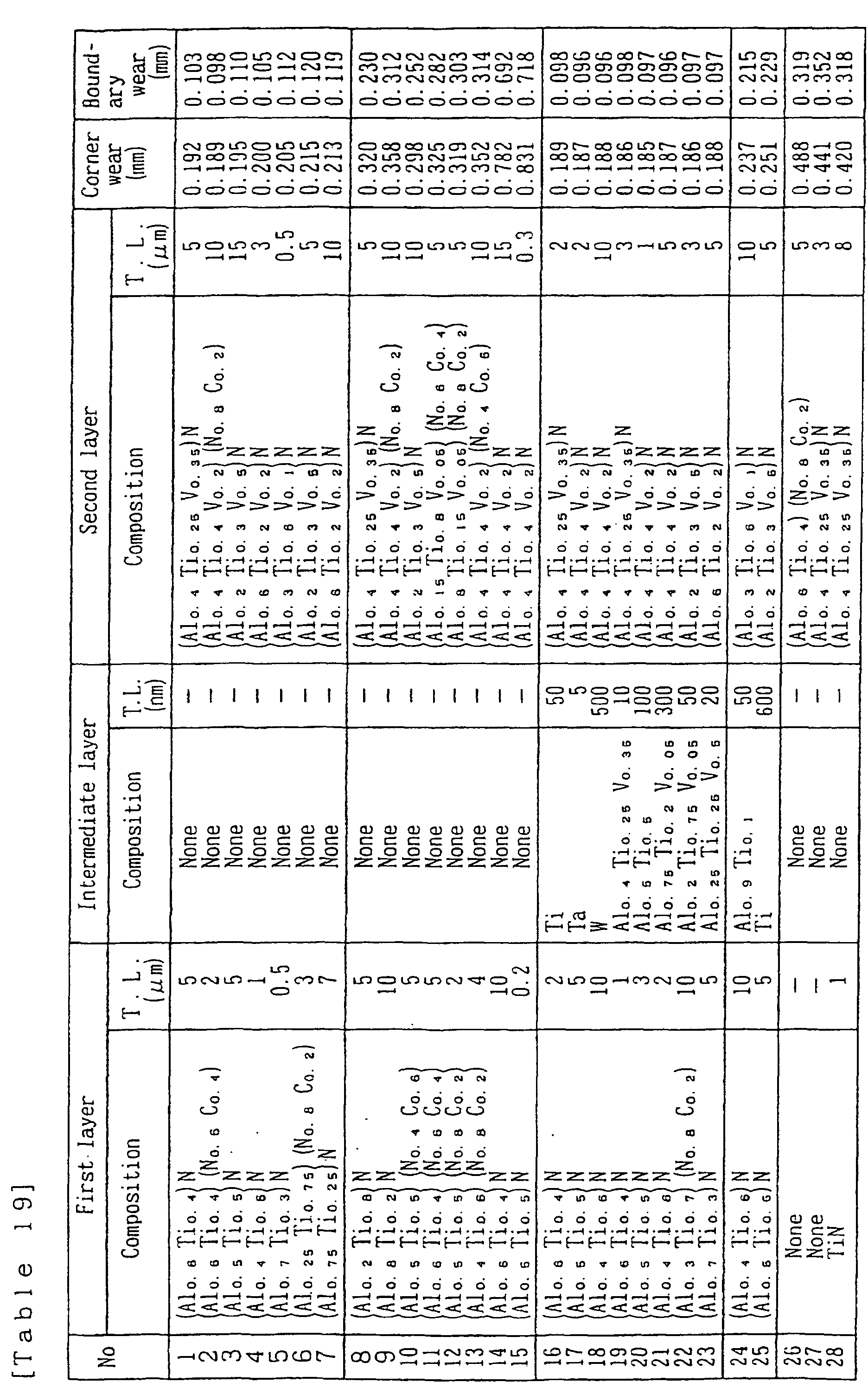
No First layer Second layer Corner wear ary (mm) Boundary wear (mm) Composition T. L. (nm) Composition T . L . (µm) 1 Ti 5 (Al0. 4 Ti0. 25 V0. 35)N 5 0.193 0.099 2 Ti 150 (Al0. 4 Ti0. 4 V0. 2) (N0. 6 C0. 4) 10 0.195 0.092 3 Zr 500 (Al0. 6 Ti0. 2 V0. 2)N 20 0.210 0.112 4 Ta 200 (Al0. 3 Ti0. 6 V0. 1)N 1 0.208 0.117 5 W 15 (Al0.2 Ti0.3 V0.s)N 8 0.215 0.108 6 Hf 100 (Al0. 5 Ti0. 15 V0. 35)N 5 0.343 0.224 7 Ta 500 (Al0. 8 Ti0. 15 V0. 05)N 15 0.429 0.321 8 Mo 50 (Al0. 15 Ti0. 8 V0. 05)N 18 0.419 0.317 9 Ti 100 (Al0. 4 Ti0. 4 V0. 2) (N0. 4 C0. 6) 5 0.352 0.333 10 Ti 600 (Al0. 4 Ti0. 25 V0. 35)N 10 0.419 0.297 11 Ta 800 (Al0. 4 Ti0. 25 V0. 35)N 10 0.450 0.324 12 Cr 2 (Al0. 4 Ti0. 25 V0. 35)N 2 0.422 0.320 13 W 1 (Al0. 4 Ti0. 4 V0. 2) (N0. 6 C0. 4) 10 0.431 0.329 14 Hf 10 (Al0. 4 Ti0. 25 V0. 35)N 25 0.780 () 0.652 () 15 Mo 150 (Al0. 4 Ti0. 25 V0. 35)N 0.5 0.853 0.732 16 None - (Al0. 6 Ti0. 4) (N0. 8 C0. 2) 5 0.488 0.319 17 None - (Al0. 4 Ti0. 25 V0. 35)N 3 0.441 0.352 18 TiN 1000 (Al0. 4 Ti0. 25 V0. 35)N 8 0.420 0.318 No First layer Second layer Corner wear (mm) Boundary wear (mm) Composition T. L. (nm) Composition T . L . (µm) 1 Al0. 4 Ti0. 25 V0. 35 5 (Al0. 4 Ti0. 25 V0. 35)N 5 0.192 0.102 2 Al0. 4 Ti0. 4 V0. 2 50 (Al0. 4 Ti0. 25 V0. 35)N 10 0.200 0.110 3 Al0. 4 Ti0. 25 V0. 35 150 (Al0. 4 Ti0. 4 V0. 2) (N0. 6 C0. 4) 20 0.193 0.098 4 Al0. 3 Ti0. 6 V0. 1 500 (Al0. 6 Ti0. 2 V0. 2)N 15 0.213 0.114 5 Al0. 2 Ti0. 3 V0. 5 200 (Al0. 3 Ti0. 6 V0. 1)N 1 0.213 0.112 6 Al0. 6 Ti0. 2 V0. 2 15 (Al0. 2 Ti0. 3 V0. 5) N 8 0.221 0.102 7 Al0. 4 Ti0. 25 V0. 35 100 (Al0. 5 Ti0. 15 V0. 35)N 5 0.351 0.232 8 Al0. 4 Ti0. 4 V0. 2 500 (Al0. 8 Ti0. 15 V0. 05)N 12 0.429 0.309 9 Al0. 4 Ti0. 4 V0. 2 50 (Al0. 15 Ti0. 8 V0. 05)N 20 0.425 0.323 10 Al0. 8 Ti0. 15 V0. 05 200 (Al0. 4 Ti0. 25 V0. 35)N 5 0.412 0.317 11 Al0. 4 Ti0. 25 V0. 35 100 (Al0. 4 Ti0. 4 V0. 2) (N0. 4 C0. 6) 5 0.350 0.331 12 Al0. 4 Ti0. 4 V0. 2 600 (Al0. 4 Ti0. 25 V0. 35)N 10 0.419 0.299 13 Al0. 4 Ti0. 4 V0. 2 800 (Al0. 4 Ti0. 25 V0. 35)N 10 0.453 0.327 14 Al0. 4 Ti0. 4 V0. 2 2 (Al0. 4 Ti0. 25 V0. 35)N 2 0.427 0.325 15 Al0. 4 Ti0. 4 V0. 2 1 (Al0. 4 Ti0. 4 V0. 2) (N0. 6 C0. 4) 10 0.436 0.334 16 Al0. 4 Ti0. 4 V0. 2 10 (Al0. 4 Ti0. 25 V0. 35)N 25 0.789 () 0. 661 () 17 Al0. 4 Ti0. 4 V0. 2 150 (Al0. 4 Ti0. 25 V0. 35)N 0.5 0.831 0.718 18 None - (Al0. 6 Ti0. 4) (N0. 8 C0. 2) 5 0.488 0.319 19 None - (Al0. 4 Ti0. 25 V0. 35)N 3 0.441 0.352 20 TiN 1000 (Al0. 4 Tio. 25 V0. 35)N 8 0.420 0.318 No. First layer Intermediate layer Second layer Corner wear (mm) Boundary wear (mm) Composition T.L. (µm) Composition T.L. (nm) Composition T.L. (µm) 1 (Al0. 6Ti0. 4)N 1 None - (Ti0. 5V0. 5)N 2 0.063 0.072 2 (Al0. 4Ti0. 6)N 1 None - (Ti0. 5V0. 5)N 2 0.073 0.079 3 (Al0. 6Ti0. 4)N 1 Ti 50 (Ti0. 5V0. 5)N 2 0.060 0.071 4 (Al0. 6Ti0. 4)N 1 Ti0. 5V0. 5 100 (Ti0. 5V0. 5)N 2 0.057 0.069 5 TiN 1 None - (Ti0. 5V0. 5)N 2 0.113 0.358 6 None - None - (Ti0. 5V0. 5)N 3 0.126 0.403 
No. First layer Intermediate layer Second layer Average number of holes Composition T.L. (µm) Composition T. L. (nm) Composition T.L. (µm) 1 (Al0. 6Ti0. 4)N 2 None - (Ti0. 7V0. 3) N 0.5 4,119 2 (Al0. 6Ti0. 4)N 0.5 None - (Ti0. 6V0. 4)N 0.5 4,219 3 (Al0. 6Ti0. 4)N 5 None - (Ti0. 6V0. 4) (N0. 6C0. 4) 5 4,351 4 (Al0. 6Ti0. 4)N 2 None - (Tio. 5V0. 5)N 3 4,503 5 (Al0. 6Ti0. 4)N 5 None - (Ti0. 5V0. 5)N 5 4,401 6 (Al0. 6Ti0. 4)N 5 None - (Ti0. 5V0. 5)N 10 4,653 7 (Al0. 6Ti0. 4)N 5 None - (Ti0. 4V0. 6)N 3 4,315 8 (Al0. 6Ti0. 4)N 5 None - (Ti0. 3V0. 7)N 5 4,198 9 (Al0. 3Ti0. 7)N 1 None - (Ti0. 5V0. 5)N 3 4,008 10 (Al0. 45Ti0. 55)N 2 None - (Ti0. 5V0. 5)N 10 4,183 11 (Al0. 7Ti0. 3)N 3 None - (Ti0. 5V0. 5)N 5 4,132 12 (Al0. 6Ti0. 4)N 2 None - (Ti0. 8V0. 2 )N 3 2,518 13 (Al0. 6Ti0. 4)N 2 None - (Ti0. 2V0. 8)N 3 2,830 14 (Al0. 2Ti0. 8) N 1 None - (Ti0. 5V0. 5)N 5 2,672 15 (Al0. 8Ti0. 2) N 1 None - (Tio. 5V0. 5)N 5 2,307 16 (Al0. 45Ti0. 55)N 5 None - (Ti0. 5V0. 5)N 20 1,813 17 (Al0. 6Ti0. 4)N 2 Ti 50 (Ti0. 5V0. 5)N 2 4,805 18 (Al0. 5Ti0. 5)N 5 Ta 5 (Ti0. 5V0. 5)N 2 4,779 19 (Al0. 6Ti0. 4)N 10 W 500 (Ti0. 4V0. 6)N 10 4,711 20 (Al0. 6Ti0. 4)N 3 Ti0. 5V0. 5 100 (Ti0. 5V0. 5)N 1 4,975 21 (Al0. 6Ti0. 4)N 5 Ti0. 6V0. 4 20 (Ti0. 4V0. 6)N 5 4,873 22 (Al0. 6Ti0. 4)N 5 Ti 600 (Ti0. 5V0. 5)N 5 3,453 23 (Al0. 7Ti0. 3)N 0.2 None - (Ti0. 5V0. 5)N 0.3 1,004 24 None - None - (Ti0. 3V0. 7)N 5 2,246 25 TiN 1 None - (Ti0. 3V0. 7)N 5 2,582 26 (Al0. 5Ti0. 5)N 5 None - None - 2,520 No First layer Second layer Average number of holes Composition T. L. (nm) Composition T . L . (µm) 1 Ti 50 (Ti0. 5 V0. 5)N 5 4625 2 V 150 (Ti0. 6 V0. 4) (N0. 8 C0. 2) 2 4352 3 Ta 500 (Ti0. 4 V0. 6)N 10 4418 4 Cr 5 (Ti0. 5 V0. 5) (N0. 6 C0. 4) 1 4532 5 Mo 300 (Ti0. 6 V0. 4) (N0. 8 C0. 2) 20 4367 6 Zr 100 (Ti0. 4 V0. 6)N 15 4395 7 Ti 100 (Ti0. 7 V0. 3)N 5 4280 8 W 50 (Ti0. 3 V0. 7) (N0. 8 C0. 2) 10 4195 9 Ti 30 (Ti0. 8 V0. 2)N 5 3408 10 Ta 200 (Ti0. 2 V0. 8) (N0. 8 C0. 2) 8 3326 11 Cr 150 (Ti0. 5 V0. 5) (N0. 4 C0. 6) 10 3218 12 Ti 600 (Ti0. 6 V0. 4)N 5 2518 13 Zr 2 (Ti0. 4 V0. 6) (N0. 6 C0. 4) 15 2317 14 Ta 50 (Ti0. 5 V0. 5)N 25 1813 15 Cr 100 (Ti0. 6 V0. 4) (N0. 8 C0. 2) 0.5 1005 16 None - (Ti0. 3 V0. 7)N 5 1798 17 TiN 1000 (Ti0. 3 V0. 7)N 5 2582 18 None - (Al0. 5 Ti0. 5)N 5 2520 No First layer Second layer Average number of holes Composition T.L. (nm) Composition T . L . (µm) 1 Ti0. 5 V0. 5 50 (Ti0. 5 V0. 5)N 5 4631 2 Ti0. 6 V0. 4 150 (Ti0. 6 V0. 4)N 10 4584 3 Ti0. 4 V0. 6 500 (Ti0. 4 V0. 6)N 15 4567 4 Ti0. 4 V0. 6 5 (Ti0. 6 V0. 4)N 1 4527 5 Ti0. 3 V0. 7 50 (Ti0. 5 V0. 5)N 5 4482 6 Ti0. 7 V0. 3 200 (Ti0. 5 V0. 5)N 10 4494 7 Ti0. 8 V0. 2 100 (Ti0. 5 V0. 5)N 20 4413 8 Ti0. 2 V0. 8 300 (Ti0. 5 V0. 5)N 5 4382 9 Ti 20 (Ti0. 6 V0. 4)N 8 4318 10 V 50 (Ti0. 4 V0. 6)N 5 4295 11 Ti0. 7 V0. 3 500 (Ti0. 7 V0. 3)N 10 4310 12 V 150 (Ti0. 7 V0. 3)N 3 4254 13 Ti 100 (Ti0. 3 V0. 7)N 5 4199 14 Ti0. 6 V0. 4 50 (Ti0. 8 V0. 2)N 5 3411 15 Ti0. 4 V0. 6 10 (Ti0. 2 V0. 8) (N0. 8 C0. 2) 8 3342 16 Ti0. 4 V0. 6 150 (Ti0. 5 V0. 5) (N0. 4 C0. 6) 10 3235 17 Ti0. 6 V0. 4 600 (Ti0. 6 V0. 4)N 5 2521 18 Ti0. 4 V0. 6 2 (Ti0. 4 V0. 6)(N0. 6 C0. 4) 15 2320 19 Ti0. 5 V0. 5 50 (Ti0. 5 V0. 5)N 25 1816 20 Ti0. 6 V0. 4 100 (Ti0. 6 V0. 4) (N0. 8 C0. 2) 0.5 1007 21 None - (Ti0. 3 V0. 7)N 5 1798 22 TiN 1000 (Ti0. 3 V0. 7)N 5 2582 23 None - (Ti0. 5 V0. 5)N 5 2520 
No First layer Second layer Average number of holes Composition T. L. (nm) Composition T . L . (µm) 1 Ti 5 (Al0. 4 Ti0. 25 V0. 35)N 5 4813 2 Ti 150 (Al0. 4 Ti0. 4 V0. 2) (N0. 6 C0. 4) 10 4921 3 Zr 500 (Al0. 6 Ti0. 2 Vo. 2)N 20 4793 4 Ta 200 (Al0. 3 Ti0. 6 V0. 1)N 1 4873 5 W 15 (Al0. 2 Ti0. 3 V0. 5)N 8 4762 6 Hf 100 (Al0. 5 Ti0. 15 V0. 35)N 5 3510 7 Ta 500 (Al0. 8 Ti0. 15 V0. 05)N 15 2018 8 Mo 50 (Al0. 15 Ti0. 8 V0. 05)N 18 3007 9 Ti 100 (Al0. 4 Ti0. 4 V0. 2) (N0. 4 C0. 6) 5 3028 10 Ti 600 (Al0. 4 Ti0. 25 V0. 35)N 10 2579 11 Ta 800 (Al0. 4 Ti0. 25 V0. 35)N 10 2108 12 Cr 2 (Al0. 4 Ti0. 25 V0. 35)N 2 2253 13 W 1 (Al0. 4 Ti0. 4 V0. 2) (N0. 6 C0. 4) 10 2019 14 Hf 10 (Al0. 4 Ti0. 25 V0. 35)N 25 1532 15 Mo 150 (Al0. 4 Ti0. 25 V0. 35)N 0.5 1003 16 None - (Al0. 6 Ti0. 4) (N0. 8 C0. 2) 5 2520 17 None - (Al0. 4 Ti0. 25 V0. 35)N 3 2213 18 TiN 1000 (Al0. 4 Ti0. 25 V0. 35)N 8 2672 No First layer Second layer Average number of holes Composition T.L. (nm) Composition T . L . (µm) 1 Al0. 4 Ti0. 25 V0. 35 5 (Al0. 4 Ti0. 25 V0. 35)N 5 4826 2 Al0. 4 Ti0. 4 V0. 2 50 (Al0. 4 Ti0. 25 V0. 35)N 10 4901 3 Al0. 4 Ti0. 25 V0. 35 150 (Al0. 4 Ti0. 4 V0. 2) (N0. 6 C0. 4) 20 4942 4 Al0. 3 Ti0. 6 V0. 1 500 (Al0. 6 Ti0. 2 V0. 2)N 15 4789 5 Al0.2 Ti0. 3 V0. 5 200 (Al0. 3 Ti0. 6 V0. 1)N 1 4880 6 Al0. 6 Ti0. 2 V0. 2 15 (Al0. 2 Ti0. 3 V0. 5)N 8 4772 7 Al0. 4 Ti0. 25 V0. 35 100 (Al0. 5 Ti0. 15 V0. 35)N 5 3508 8 Al0. 4 Ti0. 4 V0. 2 500 (Al0. 8 Ti0. 15 V0. 05)N 12 2018 9 Al0. 4 Ti0. 4 V0. 2 50 (Al0. 15 Ti0. 8 V0. 05)N 20 3013 10 Al0. 8 Ti0. 15 V0. 05 200 (Al0. 4 Ti0. 25 V0. 35)N 5 2972 11 Al0. 4 Ti0. 25 V0. 35 100 (Al0. 4 Ti0. 4 V0. 2) (N0. 4 C0. 6) 5 3019 12 Al0. 4 Ti0. 4 V0. 2 600 (Al0. 4 Ti0. 25 V0. 35)N 10 2557 13 Al0. 4 Ti0. 4 V0. 2 800 (Al0. 4 Ti0. 25 V0. 35)N 10 2092 14 Al0. 4 Ti0. 4 V0. 2 2 (Al0. 4 Ti0. 25 V0. 35)N 2 2240 15 Al0. 4 Ti0. 4 V0. 2 1 (Al0. 4 Ti0. 4 V0. 2) (N0. 6 C0. 4) 10 2004 16 Al0. 4 Ti0. 4 V0. 2 10 (Al0. 4 Ti0. 25 V0. 35)N 25 1512 17 Al0. 4 Ti0. 4 V0. 2 150 (Al0. 4 Ti0. 25 V0. 35)N 0.5 995 18 None - (Al0. 6 Ti0. 4) (N0. 8 C0. 2) 5 2520 19 None - (Al0. 4 Ti0. 25 V0. 35)N 3 2213 20 TiN 1000 (Al0. 4 Ti0. 25 V0. 35)N 8 2672 No. First layer Intermediate layer Second layer Flank wear (mm) Composition T.L (µm) Composition T. L. (nm) Composition T. L. (µm) 1 (Al0. 6Ti0. 4)N 2 None - (Ti0. 7V0. 3)N 0.5 0.104 2 (Al0. 6Ti0. 4)N 0.5 None - (Ti0. 6V0. 4)N 0.5 0.101 3 (Al0. 6Ti0. 4)N 5 None - (Ti0. 6V0. 4) (N0. 6C0. 4) 5 0.096 4 (Al0. 6Ti0. 4)N 2 None - (Ti0. 5V0. 5)N 3 0.089 5 (Al0. 6Ti0. 4)N 5 None - (Ti0. 5V0. 5)N 5 0.085 6 (Al0. 6Ti0. 4)N 5 None - (Ti0. 5V0. 5)N 10 0.080 7 (Al0. 6Ti0. 4)N 5 None - (Ti0. 4V0. 6)N 3 0.087 8 (Al0. 6Ti0. 4)N 5 None - (Ti0. 3V0. 7)N 5 0.104 9 (Al0. 3Ti0. 7)N 1 None - (Ti0. 5V0. 5)N 3 0.118 10 (Al0. 45Ti0. 55)N 2 None - (Ti0. 5V0. 5)N 10 0.111 11 (Al0. 7Ti0. 3)N 3 None - (Ti0. 5V0. 5)N 5 0.120 12 (Al0. 6Ti0. 4)N 2 None - (Ti0. 8V0. 2)N 3 0.200 13 (Al0. 6Ti0. 4)N 2 None - (Ti0. 2V0. 8)N 3 0.205 14 (Al0. 2Ti0. 8)N 1 None - (Ti0. 5V0. 5)N 5 0.216 15 (Al0. 8Ti0. 2)N 1 None - (Ti0. 5V0. 5)N 5 0.232 16 (Al0. 45Ti0. 55)N 5 None - (Ti0. 5V0. 5)N 20 0.274 17 (Al0. 6Ti0. 4)N 2 Ti 50 (Ti0. 5V0. 5)N 2 0.074 18 (Al0. 5Ti0. 5)N 5 Ta 5 (Ti0. 5V0. 5)N 2 0.077 19 (Al0. 6Ti0. 4)N 10 W 500 (Ti0. 4V0. 6)N 10 0.079 20 (Al0. 6Ti0. 4)N 3 Ti0. 5V0. 5 100 (Ti0. 5V0. 5)N 1 0.071 21 (Al0. 6Ti0. 4)N 5 Ti0. 6V0. 4 20 (Ti0. 4V0. 6)N 5 0.073 22 (Al0. 6Ti0. 4)N 5 Ti 600 (Ti0. 5V0. 5)N 5 0.282 23 (Al0. 7Ti0. 3)N 0.2 None - (Ti0. 5V0. 5)N 0.3 0.350 24 None - None - (Ti0. 3V0. 7)N 5 0.326 25 TiN 1 None - (Ti0. 3V0. 7)N 5 0.289 26 (Al0. 5Ti0. 5)N 5 None - None - 0.276 No First layer Second layer Flank wear (mm) Composition T. L. (nm) Composition T . L . (µm) 1 Ti 50 (Ti0. 5 V0. 5)N 5 0.080 2 V 150 (Ti0. 6 V0. 4) (N0. 8 C0. 2) 2 0.087 3 Ta 500 (Ti0. 4 V0. 6)N 10 0.095 4 Cr 5 (Ti0. 5 V0. 5) (N0. 6 C0. 4) 1 0.084 5 Mo 300 (Ti0. 6 V0. 4) (N0. 8 C0. 2) 20 0.091 6 Zr 100 (Ti0. 4 V0. 6)N 15 0.091 7 Ti 100 (Ti0. 7 V0. 3)N 5 0.113 8 W 50 (Ti0. 3 V0. 7) (N0. 8 C0. 2) 10 0.120 9 Ti 30 (Ti0. 8 V0. 2)N 5 0.200 10 Ta 200 (Ti0. 2 V0. 8) (N0. 8 C0. 2) 8 0.211 11 Cr 150 (Ti0. 5 V0. 5) (N0. 4 C0. 6) 10 0.237 12 Ti 600 (Ti0. 6 V0. 4)N 5 0.268 13 Zr 2 (Ti0. 4 V0. 6) (N0. 6 C0. 4) 15 0.305 14 Ta 50 (Ti0. 5 V0. 5)N 25 0.284 15 Cr 100 (Ti0. 6 V0. 4) (N0. 8 C0. 2) 0.5 0.350 16 None - (Ti0. 3 V0. 7)N 5 0.326 17 TiN 1000 (Ti0. 3 V0. 7)N 5 0.289 18 None - (Al0. 5 Ti0. 5)N 5 0.276 No First layer Second layer Flank wear (mm) Composition T. L. (nm) Composition T . L . (µm) 1 Ti0. 5 V0. 5 50 (Ti0. 5 V0. 5)N 5 0.080 2 Ti0. 6 V0. 4 150 (Ti0. 6 V0. 4)N 10 0.084 3 Ti0. 4 V0. 6 500 (Ti0. 4 V0. 6)N 15 0.084 4 Ti0. 4 V0. 6 5 (Ti0. 6 V0. 4)N 1 0.087 5 Ti0. 3 V0. 7 50 (Ti0. 5 V0. 5)N 5 0.095 6 Ti0. 7 V0. 3 200 (Ti0. 5 V0. 5)N 10 0.091 7 Ti0. 6V0. 2 100 (Ti0. 5 V0. 5)N 20 0.102 8 Ti0. 2 V0. 8 300 (Ti0. 5 V0. 5)N 5 0.098 9 Ti 20 (Ti0. 6 V0. 4)N 8 0.109 10 V 50 (Ti0. 4V0. 6)N 5 0.113 11 Ti0. 7 V0. 3 500 (Ti0. 7 V0. 3)N 10 0.109 12 V 150 (Ti0. 7 V0. 3)N 3 0.116 13 Ti 100 (Ti0. 3 V0. 7)N 5 0.120 14 Ti0. 6 V0. 4 50 (Ti0. 8 V0. 2)N 5 0.200 15 Ti0. 4 V0. 6 10 (Ti0. 2 V0. 8) (N0. 8 C0. 2) 8 0.210 16 Ti0. 4 V0. 6 150 (Ti0. 5 V0. 5)(N0. 4 C0. 6) 10 0.236 17 Ti0. 6 V0. 4 600 (Ti0. 6 V0. 4)N 5 0.266 18 Ti0. 4 V0. 6 2 (Ti0. 4 V0. 6) (N0. 6 C0. 4) 15 0.304 19 Ti0. 5 V0. 5 50 (Ti0. 5 V0. 5)N 25 0.281 20 Ti0. 6 V0. 4 100 (Ti0. 6 V0. 4) (N0. 8 C0. 2) 0.5 0. 350 21 None - (Ti0. 3 V0. 7)N 5 0.326 22 TiN 1000 (Ti0. 3 V0. 7)N 5 0.289 23 None - (Ti0. 5 V0. 5)N 5 0.276 
No First layer Second layer Flank wear (mm) Composition T. L. (nm) Composition T . L . (µm) 1 Ti 5 (Al0. 4 Ti0. 25 V0. 35)N 5 0.080 2 Ti 150 (Al0. 4 Ti0. 4 V0. 2) (N0. 6 C0. 4) 10 0.087 3 Zr 500 (Al0. 6 Ti0. 2 V0. 2)N 20 0.095 4 Ta 200 (Al0. 3 Ti0. 6 V0. 1)N 1 0.109 5 W 15 (Al0. 2 Ti0. 3 V0. 5)N 8 0.120 6 Hf 100 (Al0. 5 Ti0. 15 V0. 35)N 5 0.208 7 Ta 500 (Al0. 8 Ti0. 15 V0. 05)N 15 0.297 8 Mo 50 (Al0. 15 Ti0. 8 V0. 05)N 18 0.223 9 Ti 100 (Al0. 4 Ti0. 4 V0. 2) (N0. 4 C0. 6) 5 0.228 10 Ti 600 (Al0. 4 Ti0. 25 V0. 35)N 10 0.254 11 Ta 800 (Al0. 4 Ti0. 25 V0. 35)N 10 0.274 12 Cr 2 (Al0. 4 Ti0. 25 V0. 35)N 2 0.330 13 W 1 (Al0. 4 Ti0. 4 V0. 2) (N0. 6 C0. 4) 10 0.305 14 Hf 10 (Al0. 4 Ti0. 25 V0. 35)N 25 0.274 15 Mo 150 (Al0. 4 Ti0. 25 V0. 35)N 0.5 0.350 16 None - (Al0. 6 Ti0. 4) (N0. 8 Co. 2) 5 0.280 17 None - (Al0. 4 Ti0. 25 V0. 35) N 3 0.331 18 TiN 1000 (Al0. 4 Ti0. 25 V0. 35)N 8 0.397 No First layer Second layer Flank wear (mm) Composition T. L. (nm) Composition T . L . (µm) 1 Al0. 4 Ti0. 25 V0. 35 5 (Al0. 4 Ti0. 25 V0. 35)N 5 0.080 2 Al0. 4 Ti0. 4 V0. 2 50 (Al0. 4 Ti0. 25 V0. 35)N 10 0.084 3 Al0. 4 Ti0. 25 V0. 35 150 (Al0. 4 Ti0. 4 V0. 2) (N0. 6 C0. 4) 20 0.087 4 Al0. 3 Ti0. 6 V0. 1 500 (Al0. 6 Ti0. 2 V0. 2)N 15 0.095 5 Al0. 2 Ti0. 3 V0. 5 200 (Al0. 3 Ti0. 6 V0. 1)N 1 0.109 6 Al0. 6 Ti0. 2 V0. 2 15 (Al0. 2 Ti0. 3 V0. 5)N 8 0.120 7 Al0. 4 Ti0. 25 V0. 35 100 (Al0. 5 Ti0. 15 V0. 35)N 5 0.227 8 Al0. 4 Ti0. 4 V0. 2 500 (Al0. 8 Ti0. 15 V0. 05) N 12 0.297 9 Al0. 4 Ti0. 4 V0. 2 50 (Al0. 15 Ti0. 8 V0. 05)N 20 0.244 10 Al0. 8 Ti0. 15 V0. 05 200 (Al0. 4 Ti0. 25 V0. 35)N 5 0.200 11 Al0. 4 Ti0. 25 V0. 35 100 (Al0. 4 Ti0. 4 V0. 2) (N0. 4 C0. 6) 5 0.246 12 Al0. 4 Ti0. 4 V0. 2 600 (Al0. 4 Ti0. 25 V0. 35)N 10 0.273 13 Al0. 4 Ti0. 4 V0. 2 800 (Al0. 4 Ti0. 25 V0. 35)N 10 0.285 14 Al0. 4 Ti0. 4 V0. 2 2 (Al0. 4 Ti0. 25 V0. 35)N 2 0.319 15 Al0. 4 Ti0. 4 V0. 2 1 (Al0. 4 Ti0. 4 V0. 2) (N0. 6 C0. 4) 10 0.328 16 Al0. 4 Ti0. 4 V0. 2 10 (Al0. 4 Ti0. 25 V0. 35)N 25 0.290 17 Al0. 4 Ti0. 4 V0. 2 150 (Al0. 4 Ti0. 25 V0. 35)N 0.5 0.350 18 None - (Al0. 6 Ti0. 4) (N0. 8 C0. 2) 5 0.280 19 None - (Al0. 4 Ti0. 25 V0. 35)N 3 0.331 20 TiN 1000 (Al0. 4 Ti0. 25 V0. 35)N 8 0.297 No. First layer Intermediate layer Second layer Flank wear (mm) Composition T.L (µm) Composition T.L. (nm) Composition T.L. (µm) 1 (Al0. 6Ti0. 4)N 2 None - (Ti0. 7V0. 3)N 0.5 0.15 2 (Al0. 6Ti0. 4)N 0.5 None - (Ti0. 6V0. 4)N 0.5 0.13 3 (Al0. 6Ti0. 4)N 5 None - (Ti0. 6V0. 4) (N0. 6C0. 4) 5 0.11 4 (Al0. 6Ti0. 4)N 2 None - (Ti0. 5V0. 5)N 3 0.09 5 (Al0.6Ti0. 4)N 5 None - (Ti0. 5V0. 5)N 5 0. 08 6 (Al0. 6Ti0. 4)N 5 None - (Ti0. 5V0. 5)N 10 0.06 7 (Al0. 6Ti0. 4)N 5 None - (Ti0. 4V0. 6)N 3 0.12 8 (Al0. 6Ti0. 4)N 5 None - (Ti0. 3V0. 7)N 5 0.15 9 (Alo. 3Ti0. 7)N 1 None - (Ti0. 5V0. 5)N 3 0.18 10 (Al0. 45Ti0. 55)N 2 None - (Ti0. 5V0. 5)N 10 0.17 11 (Al0. 7Ti0. 3)N 3 None - (Ti0. 5V0. 5)N 5 0.20 12 (Al0. 6Ti0. 4)N 2 None - (Ti0. 8V0. 2)N 3 0.48 13 (Al0. 6Ti0. 4)N 2 None - (Ti0. 2V0. 8)N 3 0.51 14 (Al0. 2Ti0. 8)N 1 None - (Ti0. 5V0. 5)N 5 0.58 15 (Al0. 8Ti0. 2)N 1 None - (Ti0. 5V0. 5)N 5 0.69 16 (Al0. 45Ti0. 55)N 5 None - (Ti0. 5V0. 5)N 20 0.62 17 (Al0. 6Ti0. 4)N 2 Ti 50 (Ti0. 5V0. 5)N 2 0.05 18 (Al0. 5Ti0. 5)N 5 Ta 5 (Ti0. 5V0. 5)N 2 0.06 19 (Al0. 6Ti0. 4)N 10 W 500 (Ti0. 4V0. 6)N 10 0.06 20 (Al0. 6Ti0. 4)N 3 Ti0. 5V0. 5 100 (Ti0. 5V0. 5)N 1 0. 05 21 (Al0. 6Ti0. 4)N 5 Ti0. 6V0. 4 20 (Ti0. 4V0. 6)N 5 0.06 22 (Al0. 6Ti0. 4)N 5 Ti 600 (Ti0. 5V0. 5)N 5 0.58 23 (Al0. 7Ti0. 3)N 0.2 None - (Ti0. 5V0. 5)N 0.3 0.84 24 None - None - (Ti0. 3V0. 7)N 5 0.79 25 TiN 1 None - (Ti0. 3V0. 7)N 5 0.60 26 (Al0. 5Ti0. 5)N 5 None - None - 0.57 No First layer Second layer Flank wear (mm) Composition T. L. (nm) Composition T . L . (µm) 1 Ti 50 (Ti0. 5 V0. 5)N 5 0.06 2 V 150 (Ti0. 6 V0. 4) (N0. 8 C0. 2) 2 0.08 3 Ta 500 (Ti0. 4 V0. 6)N 10 0.09 4 Cr 5 (Ti0. 5 V0. 5) (N0. 6 C0. 4) 1 0.07 5 Mo 300 (Ti0. 6 V0. 4) (N0. 8 C0. 2) 20 0.09 6 Zr 100 (Ti0. 4 V0. 6)N 15 0.10 7 Ti 100 (Ti0. 7 V0. 3)N 5 0.15 8 W 50 (Ti0. 3 V0. 7) (N0. 8 C0. 2) 10 0.18 9 Ti 30 (Ti0. 8 V0. 2)N 5 0.48 10 Ta 200 (Ti0. 2 V0. 8) (N0. 8 C0. 2) 8 0.51 11 Cr 150 (Ti0. 5 V0. 5) (N0. 4 C0. 6) 10 0.44 12 Ti 600 (Ti0. 6 V0. 4)N 5 0.59 13 Zr 2 (Ti0. 4 V0. 6) (N0. 6 C0. 4) 15 0.75 14 Ta 50 (Ti0. 5 V0. 5)N 25 0.65 15 Cr 100 (Ti0. 6 V0. 4) (N0. 8 C0. 2) 0.5 0.83 16 None - (Ti0. 3 V0. 7)N 5 0.79 17 TiN 1000 (Ti0. 3 V0. 7)N 5 0.60 18 None - (Al0. 5 Ti0. 5)N 5 0.57 No First layer Second layer Flank wear (mm) Composition T. L. (nm) Composition T . L . (µm) 1 Ti0. 5 V0. 5 50 (Ti0. 5 V0. 5)N 5 0.06 2 Ti0. 6 V0. 4 150 (Ti0. 6 V0. 4)N 10 0.08 3 Ti0. 4 V0. 6 500 (Ti0. 4 V0. 6)N 15 0.07 4 Ti0. 4 V0. 6 5 (Ti0. 6 V0. 4)N 1 0.09 5 Ti0. 3 V0. 7 50 (Ti0. 5 V0. 5)N 5 0.12 6 Ti0. 7 V0. 3 200 (Ti0. 5 V0. 5)N 10 0.11 7 Ti0. 8 V0. 2 100 (Ti0. 5 V0. 5)N 20 0.14 8 Ti0. 2 V0. 8 300 (Ti0. 5 V0. 5)N 5 0.13 9 Ti 20 (Ti0. 6 V0. 4)N 8 0.16 10 V 50 (Ti0. 4 V0. 6)N 5 0.15 11 Ti0. 7 V0. 3 500 (Ti0. 7 V0. 3)N 10 0.18 12 V 150 (Ti0. 7 V0. 3)N 3 0.17 13 Ti 100 (Ti0. 3 V0. 7)N 5 0.18 14 Ti0. 6 V0. 4 50 (Ti0. 8 V0. 2)N 5 0.47 15 Ti0. 4 V0. 6 10 (Ti0. 2 V0. 8) (N0. 8 C0. 2) 8 0.50 16 Ti0. 4 V0. 6 150 (Ti0. 5 V0. 5) (N0. 4 C0. 6) 10 0.43 17 Ti0. 6 V0. 4 600 (Ti0. 6 V0. 4)N 5 0.60 18 Ti0. 4 V0. 6 2 (Ti0. 4 V0. 6) (N0. 6 C0. 4) 15 0.74 19 Ti0. 5 V0. 5 50 (Ti0. 5 V0. 5)N 25 0.64 20 Ti0. 6 V0. 4 100 (Ti0. 6 V0. 4) (N0. 8 C0. 2) 0.5 0.83 21 None - (Ti0. 3 V0. 7)N 5 0.79 22 TiN 1000 (Ti0. 3 V0. 7)N 5 0.60 23 None - (Ti0. 5 V0. 5)N 5 0.57 
No First layer Second layer Flank wear (mm) Composition T. L. (nm) Composition T . L . (µm) 1 Ti 5 (Al0. 4 Ti0. 25 V0. 35)N 5 0.07 2 Ti 150 (Al0. 4 Ti0. 4 V0. 2) (N0. 6 C0. 4) 10 0.06 3 Zr 500 (Al0. 6 Ti0. 2 V0. 2)N 20 0.10 4 Ta 200 (Al0. 3 Ti0. 6 V0. 1)N 1 0.15 5 W 15 (Al0. 2 Ti0. 3 V0. 5)N 8 0.13 6 Hf 100 (Al0.5 Ti0.15 V0. 35)N 5 0.47 7 Ta 500 (Al0. 8 Ti0. 15 V0. 05)N 15 0.59 8 Mo 50 (Al0. 15 Ti0. 8 V0. 05)N 18 0.39 9 Ti 100 (Al0. 4 Ti0. 4 V0. 2) (N0. 4 C0. 6) 5 0.43 10 Ti 600 (Al0. 4 Ti0. 25 V0. 35)N 10 0.58 11 Ta 800 (Al0. 4 Ti0. 25 V0. 35)N 10 0.62 12 Cr 2 (Al0. 4 Ti0. 25 V0. 35)N 2 0.78 13 W 1 (Al0. 4 Ti0. 4 V0. 2) (N0. 6 C0. 4) 10 0.75 14 Hf 10 (Al0. 4 Ti0. 25 V0. 35)N 25 0.60 15 Mo 150 (Al0. 4 Ti0. 25 V0. 35)N 0.5 0.87 16 None - (Al0. 6 Ti0. 4) (N0. 8 C0. 2) 5 0.57 17 None - (Al0. 4 Ti0. 25 V0. 35)N 3 0.79 18 TiN 1000 (Al0. 4 Ti0. 25 V0. 35)N 8 0.59 No First layer Second layer Flank wear (mm) Composition T. L. (nm) Composition T . L . (µm) 1 Al0. 4 Ti0. 25 V0. 35 5 (Al0. 4 Ti0. 25 V0. 35)N 5 0.05 2 Al0. 4 Ti0. 4 V0. 2 50 (Al0. 4 Ti0. 25 V0. 35)N 10 0.08 3 Al0. 4 Ti0. 25 V0. 35 150 (Al0. 4 Ti0. 4 V0. 2) (N0. 6 C0. 4) 20 0.09 4 Al0. 3 Ti0. 6 V0. 1 500 (Al0. 6 Ti0. 2 V0. 2)N 15 0.11 5 Al0. 2 Ti0. 3 V0. 5 200 (Al0. 3 Ti0. 6 V0. 1)N 1 0.14 6 Al0. 6 Ti0. 2 V0. 2 15 (Al0. 2 Ti0. 3 V0. 5)N 8 0.18 7 Al0. 4 Ti0. 25 V0. 35 100 (Al0. 5 Ti0. 15 V0. 35)N 5 0.45 8 Al0. 4 Ti0. 4 V0. 2 500 (Al0. 8 Ti0. 15 V0. 05)N 12 0.50 9 Al0. 4 Ti0. 4 V0. 2 50 (Al0. 15 Ti0. 8 V0. 05)N 20 0.39 10 Al0. 8 Ti0. 15 V0. 05 200 (Al0. 4 Ti0. 25 V0. 35)N 5 0.42 11 Al0. 4 Ti0. 25 V0. 35 100 (Al0. 4 Ti0. 4 V0. 2) (N0. 4 C0. 6) 5 0.44 12 Al0.4 Ti0. 4 V0. 2 600 (Al0. 4 Ti0. 25 V0. 35)N 10 0.59 13 Al0. 4 Ti0. 4 V0. 2 800 (Al0. 4 Ti0. 25 V0. 35)N 10 0.61 14 Al0. 4 Ti0. 4 V0. 2 2 (Al0. 4 Ti0. 25 V0. 35)N 2 0.79 15 Al0.4 Ti0.4 V0. 2 1 (Al0. 4 Ti0. 4 V0. 2) (N0. 6 C0. 4) 10 0.76 16 Al0. 4 Ti0. 4 V0. 2 10 (Al0. 4 Ti0. 25 V0. 35)N 25 0.69 17 Al0. 4 Ti0. 4 V0. 2 150 (Al0. 4 Ti0. 25 V0. 35)N 0.5 0.88 18 None - (Al0. 6 Ti0.4) (N0. 8 C0. 2) 5 0.57 19 None - (Al0. 4 Ti0. 25 V0. 35)N 3 0.79 20 TiN 1000 (Al0. 4 Ti0. 25 V0. 35)N 8 0.59
Claims (9)
- A member coated with a hard coating and having excellent wear resistance, the hard coating comprising:an adhesion reinforcing layer formed on a surface of the member and a second layer, wherein the adhesion reinforcing layerand the second layer is formed on the adhesion reinforcing layer and has a composition represented by the following formula:a) has a composition represented by the following formula:b) consists of any metal in the group 4A, 5A, and 6A metals;
orc) has a composition represented by the following formula: - A hard coating coated member according to claim 1, wherein the second layer has a composition represented by the following formula:
- A hard coating coated member according to claim 1, wherein the second layer has a composition represented by the following formula:
- A hard coating coated member according to any one of claims 1 to 3, wherein the adhesion reinforcing layer has a composition represented by the following formula:
- A hard coating coated member according to any one of claims 1 to 4, having an intermediate layer between the adhesion reinforcing layer having a composition represented by the formula (AlaTib)(NcCd) where 0.25≤a≤0.75, a+b=1; 0.6≤c≤1, and c+d=1, and the second layer, the intermediate layer consisting essentially of any metal in the group 4A, 5A, and 6A metals and having a thickness of 500 nm or smaller.
- A hard coating coated member according to any one of claims 1 to 4, having an intermediate layer between the adhesion reinforcing layer having a composition represented by the formula (AlaTib)(NcCd) where 0.25≤a≤0.75, a + b = 1, 0.6≤c≤1, and c+d=1, and the second layer, the intermediate layer having a thickness of 500 nm or smaller and having a composition represented by the following formula:
- A hard coating coated member according to claim 5 or 6, wherein the thickness of the entire coating is 0.8 to 50 µm.
- A hard coating coated member according to any one of claims 1 to 4, wherein the thickness of the adhesion reinforcing layer is 5 to 500 nm.
- A hard coating coated member according to any one of claims 1 to 4, wherein the total thickness of adhesion reinforcing layer and the second layer is 0.8 to 20 µm.
Applications Claiming Priority (12)
| Application Number | Priority Date | Filing Date | Title |
|---|---|---|---|
| JP30593598 | 1998-10-27 | ||
| JP30593898 | 1998-10-27 | ||
| JP30593598A JP4331807B2 (en) | 1998-10-27 | 1998-10-27 | Hard film and hard film coated member with excellent wear resistance |
| JP30593998 | 1998-10-27 | ||
| JP30593798 | 1998-10-27 | ||
| JP30593998A JP2000129425A (en) | 1998-10-27 | 1998-10-27 | Hard film excellent in wear resistance and hard film coated member |
| JP30593698 | 1998-10-27 | ||
| JP30593698A JP2000129424A (en) | 1998-10-27 | 1998-10-27 | Hard film excellent in wear resistance and hard film coated member |
| JP30593498 | 1998-10-27 | ||
| JP30593898A JP4350822B2 (en) | 1998-10-27 | 1998-10-27 | Hard film and hard film coated member with excellent wear resistance |
| JP30593798A JP3934263B2 (en) | 1998-10-27 | 1998-10-27 | Hard film and hard film coated member with excellent wear resistance |
| JP30593498 | 1998-10-27 |
Publications (2)
| Publication Number | Publication Date |
|---|---|
| EP0999290A1 EP0999290A1 (en) | 2000-05-10 |
| EP0999290B1 true EP0999290B1 (en) | 2005-03-23 |
Family
ID=27554548
Family Applications (1)
| Application Number | Title | Priority Date | Filing Date |
|---|---|---|---|
| EP99108517A Expired - Lifetime EP0999290B1 (en) | 1998-10-27 | 1999-05-04 | Wear-resistant coated member |
Country Status (5)
| Country | Link |
|---|---|
| US (1) | US6296928B1 (en) |
| EP (1) | EP0999290B1 (en) |
| KR (1) | KR100633286B1 (en) |
| AT (1) | ATE291648T1 (en) |
| DE (1) | DE69924341T2 (en) |
Cited By (1)
| Publication number | Priority date | Publication date | Assignee | Title |
|---|---|---|---|---|
| US7510608B2 (en) | 2006-01-20 | 2009-03-31 | Kobe Steel Ltd. | Hard coating film |
Families Citing this family (19)
| Publication number | Priority date | Publication date | Assignee | Title |
|---|---|---|---|---|
| JP3637882B2 (en) † | 2000-08-31 | 2005-04-13 | 住友電気工業株式会社 | Surface coated boron nitride sintered body tool |
| ATE343659T1 (en) | 2000-12-28 | 2006-11-15 | Kobe Steel Ltd | HARD MATERIAL LAYER FOR CUTTING TOOLS |
| US6589602B2 (en) † | 2001-04-17 | 2003-07-08 | Toshiba Tungaloy Co., Ltd. | Highly adhesive surface-coated cemented carbide and method for producing the same |
| DE10233222B4 (en) * | 2001-07-23 | 2007-03-01 | Kabushiki Kaisha Kobe Seiko Sho (Kobe Steel, Ltd.), Kobe | Hard wear-resistant layer, method of forming same and use |
| US7211138B2 (en) * | 2003-02-07 | 2007-05-01 | Kabushiki Kaisha Kobe Seiko Sho (Kobe Steel, Ltd.) | Hard film, method of forming the same and target for hard film formation |
| JP2004345078A (en) * | 2003-04-30 | 2004-12-09 | Sumitomo Electric Ind Ltd | PVD coated cutting tool |
| JP3853757B2 (en) * | 2003-05-30 | 2006-12-06 | ユニオンツール株式会社 | Hard coating for cutting tools |
| JP3621943B2 (en) | 2003-07-25 | 2005-02-23 | 三菱重工業株式会社 | High wear resistance and high hardness coating |
| JP2005271190A (en) * | 2003-12-05 | 2005-10-06 | Sumitomo Electric Hardmetal Corp | Surface coated cutting tool |
| GB2425780B (en) | 2005-04-27 | 2007-09-05 | Univ Sheffield Hallam | PVD coated substrate |
| JP4699978B2 (en) * | 2006-08-09 | 2011-06-15 | 株式会社神戸製鋼所 | Hard coating material |
| EP2149624B1 (en) * | 2008-07-31 | 2012-08-08 | Sulzer Metaplas GmbH | Multilayer film-coated member and method for producing it |
| EP2149620B1 (en) * | 2008-07-31 | 2020-04-29 | Oerlikon Surface Solutions AG, Pfäffikon | Multilayer film-coated member and method for producing it |
| KR101344170B1 (en) | 2009-12-17 | 2013-12-20 | 스미토모덴키고교가부시키가이샤 | Cloth turning tool |
| MX346949B (en) | 2010-11-26 | 2017-04-06 | Sumitomo Electric Hardmetal Corp | Surface coated sintered body. |
| JP2013000773A (en) * | 2011-06-16 | 2013-01-07 | Sumitomo Electric Ind Ltd | Coated rotating tool |
| KR101551963B1 (en) * | 2013-09-12 | 2015-09-10 | 현대자동차주식회사 | Coating material for aluminum die casting and method for coating the same |
| US11821073B2 (en) * | 2018-10-26 | 2023-11-21 | Oerlikon Surface Solutions Ag, Pfäffikon | Vanadium aluminium nitride (VAlN) micro alloyed with Ti and/or Si |
| JP7372002B1 (en) | 2022-02-15 | 2023-10-31 | Seavac株式会社 | hard coating |
Family Cites Families (13)
| Publication number | Priority date | Publication date | Assignee | Title |
|---|---|---|---|---|
| JPS60248879A (en) | 1984-05-23 | 1985-12-09 | Toshiba Tungaloy Co Ltd | Surface coated hard alloy and its production |
| SE453369C (en) * | 1986-05-28 | 1989-10-16 | Vni Instrument Inst | Durable Coating for Cutting Tools and Procedure for Coating |
| JP2917312B2 (en) * | 1989-09-29 | 1999-07-12 | 住友電気工業株式会社 | Surface-coated carbide members for cutting and wear-resistant tools |
| JP3045184B2 (en) | 1990-12-21 | 2000-05-29 | エムエムシーコベルコツール株式会社 | Wear-resistant hard coating, method for forming the same, and wear-resistant hard coating-coated tool |
| JPH0588309A (en) | 1991-09-27 | 1993-04-09 | Fuji Photo Film Co Ltd | Direct positive image forming method and exposing device |
| DE4421144C2 (en) * | 1993-07-21 | 2003-02-13 | Unaxis Balzers Ag | Coated tool with increased service life |
| JP3249277B2 (en) | 1993-12-17 | 2002-01-21 | 東芝タンガロイ株式会社 | Wear resistant coating |
| JP2793772B2 (en) | 1994-05-13 | 1998-09-03 | 神鋼コベルコツール株式会社 | Hard film coated tools and hard film coated members with excellent adhesion |
| JP3120354B2 (en) | 1995-01-13 | 2000-12-25 | セイコーエプソン株式会社 | Image processing method and image processing apparatus |
| JPH1018024A (en) * | 1996-07-05 | 1998-01-20 | Hitachi Metals Ltd | Coated hard member |
| JP4528373B2 (en) | 1997-02-20 | 2010-08-18 | 住友電工ハードメタル株式会社 | Coated tool and manufacturing method thereof |
| EP0846784B1 (en) * | 1996-12-04 | 2004-09-08 | Sumitomo Electric Industries, Ltd. | Coated tool and method of manufacturing the same |
| JP3250966B2 (en) | 1996-12-04 | 2002-01-28 | 住友電気工業株式会社 | Coated cutting tool and manufacturing method thereof |
-
1999
- 1999-05-04 US US09/304,055 patent/US6296928B1/en not_active Expired - Lifetime
- 1999-05-04 KR KR1019990015983A patent/KR100633286B1/en not_active Expired - Lifetime
- 1999-05-04 EP EP99108517A patent/EP0999290B1/en not_active Expired - Lifetime
- 1999-05-04 DE DE69924341T patent/DE69924341T2/en not_active Expired - Lifetime
- 1999-05-04 AT AT99108517T patent/ATE291648T1/en not_active IP Right Cessation
Cited By (3)
| Publication number | Priority date | Publication date | Assignee | Title |
|---|---|---|---|---|
| US7510608B2 (en) | 2006-01-20 | 2009-03-31 | Kobe Steel Ltd. | Hard coating film |
| US7592061B1 (en) | 2006-01-20 | 2009-09-22 | Kobe Steel, Ltd. | Hard coating film |
| DE102006062798B4 (en) * | 2006-01-20 | 2014-08-07 | Kabushiki Kaisha Kobe Seiko Sho | Laminate hard coating and method of making the same |
Also Published As
| Publication number | Publication date |
|---|---|
| HK1027383A1 (en) | 2001-01-12 |
| DE69924341D1 (en) | 2005-04-28 |
| KR100633286B1 (en) | 2006-10-11 |
| KR20000028568A (en) | 2000-05-25 |
| EP0999290A1 (en) | 2000-05-10 |
| US6296928B1 (en) | 2001-10-02 |
| ATE291648T1 (en) | 2005-04-15 |
| DE69924341T2 (en) | 2006-01-19 |
Similar Documents
| Publication | Publication Date | Title |
|---|---|---|
| US6296928B1 (en) | Hard coating coated member having excellent wear resistance | |
| EP1992713B1 (en) | Hard coating excellent in wear resistance and in oxidation resistance and target for forming the same | |
| EP1710326B1 (en) | Surface-coated cutting tool | |
| US7901796B2 (en) | Coated cutting tool and manufacturing method thereof | |
| US7018726B2 (en) | Cemented carbide and cutting tool | |
| JP3417907B2 (en) | Multi-layer coating tool | |
| EP0947607B1 (en) | Members with multi-layer coatings | |
| US5580653A (en) | Hard coating having excellent wear resistance properties, and hard coating coated member | |
| EP1382709B1 (en) | Coated tool | |
| EP1939328B1 (en) | Multilayered coated cutting tool | |
| US7851075B2 (en) | Work piece with a hard film of ALCR-containing material, and process for its production | |
| US7651792B2 (en) | Hard films, multilayer hard films, and production methods thereof | |
| EP1842610A1 (en) | Surface-coated cutting tool and process for producing the same | |
| KR20160050056A (en) | A coated cutting tool and a method for coating the cutting tool | |
| JP2022540554A (en) | Method for manufacturing coated cutting tools and coated cutting tools | |
| EP1249514A1 (en) | Surface coated sintered alloy member | |
| US9551062B2 (en) | Hard film for machining tools and hard film-coated metal machining tool | |
| JP2840541B2 (en) | Hard coating, hard coating tool and hard coating member excellent in wear resistance | |
| US20070160843A1 (en) | Coated cemented carbide inserts | |
| JP4350822B2 (en) | Hard film and hard film coated member with excellent wear resistance | |
| HK1027383B (en) | Wear-resistant coated member | |
| JP3836640B2 (en) | Hard film and hard film coated member with excellent wear resistance | |
| JP3934263B2 (en) | Hard film and hard film coated member with excellent wear resistance | |
| JPH11350111A (en) | Super hard film-coated tool member | |
| JP2008055558A (en) | Hard coating for cutting tools |
Legal Events
| Date | Code | Title | Description |
|---|---|---|---|
| PUAI | Public reference made under article 153(3) epc to a published international application that has entered the european phase |
Free format text: ORIGINAL CODE: 0009012 |
|
| AK | Designated contracting states |
Kind code of ref document: A1 Designated state(s): AT BE CH CY DE DK ES FI FR GB GR IE IT LI LU MC NL PT SE |
|
| AX | Request for extension of the european patent |
Free format text: AL;LT;LV;MK;RO;SI |
|
| RAP1 | Party data changed (applicant data changed or rights of an application transferred) |
Owner name: MMC KOBELCO TOOL CO., LTD. |
|
| 17P | Request for examination filed |
Effective date: 20000907 |
|
| AKX | Designation fees paid |
Free format text: AT BE CH CY DE DK ES FI FR GB GR IE IT LI LU MC NL PT SE |
|
| 17Q | First examination report despatched |
Effective date: 20020410 |
|
| GRAP | Despatch of communication of intention to grant a patent |
Free format text: ORIGINAL CODE: EPIDOSNIGR1 |
|
| GRAS | Grant fee paid |
Free format text: ORIGINAL CODE: EPIDOSNIGR3 |
|
| GRAA | (expected) grant |
Free format text: ORIGINAL CODE: 0009210 |
|
| RAP1 | Party data changed (applicant data changed or rights of an application transferred) |
Owner name: MITSUBISHI MATERIALS KOBE TOOLS CORPORATION |
|
| AK | Designated contracting states |
Kind code of ref document: B1 Designated state(s): AT BE CH CY DE DK ES FI FR GB GR IE IT LI LU MC NL PT SE |
|
| PG25 | Lapsed in a contracting state [announced via postgrant information from national office to epo] |
Ref country code: NL Free format text: LAPSE BECAUSE OF FAILURE TO SUBMIT A TRANSLATION OF THE DESCRIPTION OR TO PAY THE FEE WITHIN THE PRESCRIBED TIME-LIMIT Effective date: 20050323 Ref country code: LI Free format text: LAPSE BECAUSE OF FAILURE TO SUBMIT A TRANSLATION OF THE DESCRIPTION OR TO PAY THE FEE WITHIN THE PRESCRIBED TIME-LIMIT Effective date: 20050323 Ref country code: FI Free format text: LAPSE BECAUSE OF FAILURE TO SUBMIT A TRANSLATION OF THE DESCRIPTION OR TO PAY THE FEE WITHIN THE PRESCRIBED TIME-LIMIT Effective date: 20050323 Ref country code: ES Free format text: LAPSE BECAUSE OF FAILURE TO SUBMIT A TRANSLATION OF THE DESCRIPTION OR TO PAY THE FEE WITHIN THE PRESCRIBED TIME-LIMIT Effective date: 20050323 Ref country code: CH Free format text: LAPSE BECAUSE OF FAILURE TO SUBMIT A TRANSLATION OF THE DESCRIPTION OR TO PAY THE FEE WITHIN THE PRESCRIBED TIME-LIMIT Effective date: 20050323 Ref country code: BE Free format text: LAPSE BECAUSE OF FAILURE TO SUBMIT A TRANSLATION OF THE DESCRIPTION OR TO PAY THE FEE WITHIN THE PRESCRIBED TIME-LIMIT Effective date: 20050323 Ref country code: AT Free format text: LAPSE BECAUSE OF FAILURE TO SUBMIT A TRANSLATION OF THE DESCRIPTION OR TO PAY THE FEE WITHIN THE PRESCRIBED TIME-LIMIT Effective date: 20050323 |
|
| REG | Reference to a national code |
Ref country code: GB Ref legal event code: FG4D |
|
| REG | Reference to a national code |
Ref country code: CH Ref legal event code: EP |
|
| REG | Reference to a national code |
Ref country code: IE Ref legal event code: FG4D |
|
| REF | Corresponds to: |
Ref document number: 69924341 Country of ref document: DE Date of ref document: 20050428 Kind code of ref document: P |
|
| PG25 | Lapsed in a contracting state [announced via postgrant information from national office to epo] |
Ref country code: LU Free format text: LAPSE BECAUSE OF NON-PAYMENT OF DUE FEES Effective date: 20050504 Ref country code: IE Free format text: LAPSE BECAUSE OF NON-PAYMENT OF DUE FEES Effective date: 20050504 Ref country code: CY Free format text: LAPSE BECAUSE OF FAILURE TO SUBMIT A TRANSLATION OF THE DESCRIPTION OR TO PAY THE FEE WITHIN THE PRESCRIBED TIME-LIMIT Effective date: 20050504 |
|
| PG25 | Lapsed in a contracting state [announced via postgrant information from national office to epo] |
Ref country code: MC Free format text: LAPSE BECAUSE OF NON-PAYMENT OF DUE FEES Effective date: 20050531 |
|
| REG | Reference to a national code |
Ref country code: HK Ref legal event code: GR Ref document number: 1027383 Country of ref document: HK |
|
| PG25 | Lapsed in a contracting state [announced via postgrant information from national office to epo] |
Ref country code: GR Free format text: LAPSE BECAUSE OF FAILURE TO SUBMIT A TRANSLATION OF THE DESCRIPTION OR TO PAY THE FEE WITHIN THE PRESCRIBED TIME-LIMIT Effective date: 20050623 Ref country code: DK Free format text: LAPSE BECAUSE OF FAILURE TO SUBMIT A TRANSLATION OF THE DESCRIPTION OR TO PAY THE FEE WITHIN THE PRESCRIBED TIME-LIMIT Effective date: 20050623 |
|
| NLV1 | Nl: lapsed or annulled due to failure to fulfill the requirements of art. 29p and 29m of the patents act | ||
| PG25 | Lapsed in a contracting state [announced via postgrant information from national office to epo] |
Ref country code: PT Free format text: LAPSE BECAUSE OF FAILURE TO SUBMIT A TRANSLATION OF THE DESCRIPTION OR TO PAY THE FEE WITHIN THE PRESCRIBED TIME-LIMIT Effective date: 20050907 |
|
| REG | Reference to a national code |
Ref country code: CH Ref legal event code: PL |
|
| ET | Fr: translation filed | ||
| PLBE | No opposition filed within time limit |
Free format text: ORIGINAL CODE: 0009261 |
|
| STAA | Information on the status of an ep patent application or granted ep patent |
Free format text: STATUS: NO OPPOSITION FILED WITHIN TIME LIMIT |
|
| REG | Reference to a national code |
Ref country code: IE Ref legal event code: MM4A |
|
| 26N | No opposition filed |
Effective date: 20051227 |
|
| PG25 | Lapsed in a contracting state [announced via postgrant information from national office to epo] |
Ref country code: SE Free format text: LAPSE BECAUSE OF FAILURE TO SUBMIT A TRANSLATION OF THE DESCRIPTION OR TO PAY THE FEE WITHIN THE PRESCRIBED TIME-LIMIT Effective date: 20050623 |
|
| REG | Reference to a national code |
Ref country code: FR Ref legal event code: TP |
|
| REG | Reference to a national code |
Ref country code: FR Ref legal event code: PLFP Year of fee payment: 18 |
|
| REG | Reference to a national code |
Ref country code: FR Ref legal event code: PLFP Year of fee payment: 19 |
|
| REG | Reference to a national code |
Ref country code: FR Ref legal event code: PLFP Year of fee payment: 20 |
|
| PGFP | Annual fee paid to national office [announced via postgrant information from national office to epo] |
Ref country code: DE Payment date: 20180522 Year of fee payment: 20 |
|
| PGFP | Annual fee paid to national office [announced via postgrant information from national office to epo] |
Ref country code: FR Payment date: 20180522 Year of fee payment: 20 Ref country code: IT Payment date: 20180530 Year of fee payment: 20 |
|
| PGFP | Annual fee paid to national office [announced via postgrant information from national office to epo] |
Ref country code: GB Payment date: 20180518 Year of fee payment: 20 |
|
| REG | Reference to a national code |
Ref country code: DE Ref legal event code: R071 Ref document number: 69924341 Country of ref document: DE |
|
| REG | Reference to a national code |
Ref country code: GB Ref legal event code: PE20 Expiry date: 20190503 |
|
| PG25 | Lapsed in a contracting state [announced via postgrant information from national office to epo] |
Ref country code: GB Free format text: LAPSE BECAUSE OF EXPIRATION OF PROTECTION Effective date: 20190503 |