EP0999035A2 - Paperboard trays, method and apparatus for forming such trays - Google Patents
Paperboard trays, method and apparatus for forming such trays Download PDFInfo
- Publication number
- EP0999035A2 EP0999035A2 EP99121706A EP99121706A EP0999035A2 EP 0999035 A2 EP0999035 A2 EP 0999035A2 EP 99121706 A EP99121706 A EP 99121706A EP 99121706 A EP99121706 A EP 99121706A EP 0999035 A2 EP0999035 A2 EP 0999035A2
- Authority
- EP
- European Patent Office
- Prior art keywords
- paperboard
- inflatable bag
- tray
- stationary die
- die member
- Prior art date
- Legal status (The legal status is an assumption and is not a legal conclusion. Google has not performed a legal analysis and makes no representation as to the accuracy of the status listed.)
- Withdrawn
Links
Images


Classifications
-
- B—PERFORMING OPERATIONS; TRANSPORTING
- B29—WORKING OF PLASTICS; WORKING OF SUBSTANCES IN A PLASTIC STATE IN GENERAL
- B29C—SHAPING OR JOINING OF PLASTICS; SHAPING OF MATERIAL IN A PLASTIC STATE, NOT OTHERWISE PROVIDED FOR; AFTER-TREATMENT OF THE SHAPED PRODUCTS, e.g. REPAIRING
- B29C51/00—Shaping by thermoforming, i.e. shaping sheets or sheet like preforms after heating, e.g. shaping sheets in matched moulds or by deep-drawing; Apparatus therefor
- B29C51/26—Component parts, details or accessories; Auxiliary operations
- B29C51/28—Component parts, details or accessories; Auxiliary operations for applying pressure through the wall of an inflated bag or diaphragm
-
- B—PERFORMING OPERATIONS; TRANSPORTING
- B29—WORKING OF PLASTICS; WORKING OF SUBSTANCES IN A PLASTIC STATE IN GENERAL
- B29C—SHAPING OR JOINING OF PLASTICS; SHAPING OF MATERIAL IN A PLASTIC STATE, NOT OTHERWISE PROVIDED FOR; AFTER-TREATMENT OF THE SHAPED PRODUCTS, e.g. REPAIRING
- B29C43/00—Compression moulding, i.e. applying external pressure to flow the moulding material; Apparatus therefor
- B29C43/02—Compression moulding, i.e. applying external pressure to flow the moulding material; Apparatus therefor of articles of definite length, i.e. discrete articles
- B29C43/10—Isostatic pressing, i.e. using non-rigid pressure-exerting members against rigid parts or dies
- B29C43/12—Isostatic pressing, i.e. using non-rigid pressure-exerting members against rigid parts or dies using bags surrounding the moulding material or using membranes contacting the moulding material
-
- B—PERFORMING OPERATIONS; TRANSPORTING
- B31—MAKING ARTICLES OF PAPER, CARDBOARD OR MATERIAL WORKED IN A MANNER ANALOGOUS TO PAPER; WORKING PAPER, CARDBOARD OR MATERIAL WORKED IN A MANNER ANALOGOUS TO PAPER
- B31B—MAKING CONTAINERS OF PAPER, CARDBOARD OR MATERIAL WORKED IN A MANNER ANALOGOUS TO PAPER
- B31B50/00—Making rigid or semi-rigid containers, e.g. boxes or cartons
- B31B50/59—Shaping sheet material under pressure
- B31B50/592—Shaping sheet material under pressure using punches or dies
Definitions
- the present invention relates to the formation of articles from paperboard, and more particularly to the formation of trays from paperboard or similar stock. Specifically, it concerns formed paper trays per se, and a method and an apparatus for forming such trays.
- Containers in the form of shallow-drawn trays are well known for use in packaging fresh foods such as vegetables. It has been a common practice in the art to form such trays from synthetic materials such as expanded polystyrene or the like. These expanded polystyrene trays find widespread use in various sectors of the food industry because of their relatively low prices, adequate mechanical strength and waterproofness. However, they have not gained wider consumer acceptance because of environmental concerns related to the use of expanded polystyrene and particularly to the well-known disposability problems. Specifically, incineration is a most commonly used method for disposing such expanded polystyrene. However, because of the light burning temperature of expanded polystyrene, incinerators are subject to damages and also to emitting black smoke or hazardous gases.
- paperboard has been used as an alternative material that provides a suitable replacement for expanded polystyrene. Examples of such paperboard trays are described in Japanese Laid Open Patent Application Nos. 9-142432 and 9-254280.
- Japanese Laid Open Patent Application No. 9-142432 discloses a paperboard tray that can be manufactured by compressing two sheets of paper and an intervening layer of thermoplastic material while heating these layers. Also, Japanese Laid Open Patent Application No. 9-254280 discloses thermally bonding a thermoplastic film to a flange portion of a sheet of paper, followed by drawing trays from such a composite blank via vacuum forming or the like.
- paperboard trays formed by the method of Japanese Laid Open Patent Application No. 9-142432 are not entirely free from the environmental problems associated with their disposal because they use the intervening thermoplastic film to provide waterproofness.
- paperboard trays are typically formed by a press which compresses paperboard blanks between a male and a female dies.
- a die set is relatively costly because strict manufacturing tolerances are required for the dies to produce a high-quality product with an acceptably small rate of tearing and other defects.
- the paperboard trays manufactured by compressing paperboard blanks between two mating dies are prone to the presence of wrinkles in rounded corners of the trays where greater deformations occur to the paperboard.
- Paperboard trays manufactured by using the method of Japanese Laid Open Patent Application No. 9-254280 not only cannot avoid the environmental problems of disposal due to the partial use of the thermoplastic film but also suffer from the relatively high cost of manufacture because the paperboard stock needs to be preformed to have a flange to which the thermoplastic film is bonded in a later step.
- Another object of the invention is to provide such a method and apparatus which can be used to form paperboard trays in a manner that controls wrinkling of portions subjected to greater deformations during forming.
- a paperboard tray which is formed by using a stationary die member and an inflatable bag member supplied with a controllable amount of fluid to compress a paperboard blank placed between the stationary die member and the inflatable bag member into a desired tray shape.
- the stationary die member and the inflatable bag are heated during compressing of the paperboard blank into the desired tray shape.
- the paperboard blank used is corrugated paperboard.
- a method for forming a paperboard tray comprising the steps of: heating an inflatable bag member and a stationary die member; placing a paperboard blank in position between the inflatable bag member and the stationary die member; and supplying a controllable amount of fluid to the inflatable bag member to inflate the bag member so that the paperboard blank may be compressed into a desired tray shape.
- the stationary die member has lubricant mean provided in or near its periphery so that the paperboard blank can readily move relative to the stationary die member.
- an apparatus for forming a paperboard blank into a tray comprising: a stationary die member; means for heating the stationary die member; an inflatable bag member; a source of fluid to be connected to the inflatable bag member; means for heating the inflatable bag member; and means for supplying a controllable amount of the fluid from the fluid source to the inflatable bag so that the inflatable bag member gradually compresses paperboard blank against the stationary die member to produce a paperboard tray.
- the apparatus further includes means for removing air from a plenum occurring between the paperboard blank and the stationary die member during the compressing step.
- the apparatus further includes means for providing lubrication to a ring portion of the stationary die member so that the paperboard blank can readily move relative to the die member.
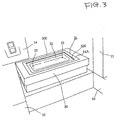
- Figure 1 shows a paperboard tray T that can be manufactured using the method and apparatus of the present invention. It should be noted that the tray T is coated on its inside surface with a thin film of water repellent paste to provide waterproofness for the tray.
- paperboard stock examples include corrugated paperboard, paperboard normally used to fabricate a commercially available waterproof milk carton, etc.
- Figure 2 shows a paperboard tray forming machine A according to the present invention, which has a rigid frame structure 1.
- the frame structure 1 comprises an H-shaped bottom stand 10, a horizontal top plate 12 and four support posts 11 extending vertically between the bottom stand 10 and the horizontal top plate 12 to provide mechanical support for the machine.
- the paperboard tray forming machine A comprises a stationary lower die assembly 30 disposed centrally above the bottom stand 10, and a movable upper press assembly, generally designated at 18, which can be moved for vertical reciprocation relative to the stationary lower die assembly 30.
- the stationary lower die assembly 30 has a heater device for heating a female die 31 formed in the die assembly 30.
- the stationary lower die assembly 30 is generally made of metal.
- the female die 31 is made of wood and is removably mounted in a generally rectangular recess 300 which is formed in the lower die assembly 30.
- the female die 31 includes a perimetral outer portion 322, a generally rectangular ring portion 320 which is surrounded by, and slightly recessed from, the perimetral outer portion 322, and a die cavity 32 surrounded by the ring portion 320. Since the female die 31 is made of wood, it can be fabricated at a relatively low cost. It should be noted, of course, that the female die 31 may be made of metal or other materials.
- the die cavity 32 includes a vent hole 33 formed at every corner of the bottom thereof to remove air from the cavity during the forming process.
- the vent holes 33 are in communication with a manifold 34 which is pneumatically connected to a vacuum pump or the like (not shown).
- the movable upper press assembly 18 includes an inflatable bag or press member 20 which is made of a sheet of rubber or similar material. In one embodiment of the invention, a 2 mm thick rubber sheet is used to fabricate the inflatable bag 20.
- the inflatable bag 20 is sealingly attached to a generally rectangular mounting plate 21 and is normally in a slightly inflated condition.
- the inflatable bag 20 is pneumatically connected to a source of pressurized air (not shown) via a control valve (not shown) to supply a controllable amount of pressurized air to the inflatable bag 20 so that it may be inflated during forming and deflated during removal of an formed tray.
- a control valve not shown
- Nitrogen gas or other gases or hydraulic fluids may be used in place of air to inflate the inflatable bag 20.
- the mounting plate 21 includes an infrared heating device (not shown) which is enclosed within the inflatable bag 20. With this arrangement, the infrared heating device can heat the inflatable bag 20 in an efficient and effective manner.
- the paperboard tray forming machine A includes a source of pressurized air (not shown) for
- the movable upper press assembly 18 also includes a movable press support plate 23 from which two coil springs 22 depend to normally support the mounting plate 21 and the inflatable bag 20 above the stationary lower die assembly 30.
- the press support plate 23 is vertically movable relative to the stationary top plate 12.
- an air cylinder assembly S Disposed on top of the stationary top plate 12 is an air cylinder assembly S which extends vertically and is attached to the top plate 12 by means of bolts.
- the air cylinder assembly S has a piston rod 15 extending downwardly through a support plate 13 for attachment to the movable press support plate 23.
- the movable press support plate 23 and the mounting plate 21 and accordingly the inflatable bag 20 can be driven toward the female die 31.
- Other drive mechanisms such as a hydraulic cylinder or a screw press (not shown) may be used in place of the air cylinder.
- the mounting plate 21 includes a vertically disposed guide plate 24 attached thereto and having an oblong aperture 25 formed therein for receipt of a pin 26 attached to the press support plate 23.
- the mounting plate 21 for the inflatable bag 20 can be moved between a lower forming position and an upper tray removal position accurately without deviating from a vertical path defined by the oblong aperture 25.
- a front panel 14 is attached to one of the support posts 11 to mount various control switches and displays thereon.
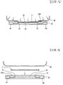
- Figure 4 shows an unformed paperboard blank 5 between the inflatable bag 20 and the female die 31 prior to the forming operation.
- the female die 31 Before the initiation of the forming operation, the female die 31 is preheated to 70 to 80 °C while, at the same time, the inflatable bag 20 is preheated to approximately 100 °C using the infrared heating device. Other temperature values to which the female die 31 and the inflatable bag 20 are heated may be selected depending upon the type of material from which the tray is drawn.
- the unformed paperboard blank 5 is then placed on the female die 31 by fitting it snugly onto the ring portion 320 surrounding the die cavity 32.
- the next step is to operate the air cylinder assembly S to move the inflatable bag 20, which is in a somewhat inflated condition, downwardly so as to compress the papaerboard blank 5 against the bottom of the die cavity 32.
- the control valve (not shown) is operated such that the inflatable bag 20 is supplied with an additional amount of pressurized air to further inflate the inflatable bag.
- the vacuum pump or the like (not shown) to remove air from a plenum occurring between the paperboard blank 5 and the die cavity 32 so that the paperboard blank may take exactly the same shape as defined by the die cavity 32.
- the heating of the female die 31 and the inflatable bag 20 to their predetermined temperatures will cause the sandwiched paperboard blank 5 to become heated, facilitating the drawing of the blank into the die cavity 32. Also, since the paperboard blank 5 is urged against the inside surface of the die cavity 32 by supplying a progressive amount of pressurized air to the inflatable bag 20, a uniform pressure is attained all over portions of the inflatable bag 20 which are in contact with the paperboard blank 5, resulting in the formation of the blank to a desired shape.
- the inflatable bag 20 first acts to clamp the periphery of the blank between it and the ring portion 320 of the female die 31. When, in this condition, the inflatable bag 20 is further inflated, it will deform the paperboard blank 5 progressively and ultimately cause it to engage the inside surface of the die cavity 32. It should be noted that this arrangement can control wrinkling in portions of a formed tray where greater deformations occur, since the inflatable bag 20 is progressively inflated to gradually deform the paperboard blank 5 into the die cavity without drawing an excess amount of paperboard into the cavity.
- the inflatable bag 20 is deflated by allowing pressurized air to escape from the bag, while, at the same time, it is moved upward to the tray removal position.
- the formed paperboard tray is then removed, as shown in Figure 6. After removal of the tray from the die cavity 32, it is allowed to cool, and excess paper is trimmed to convert the formed tray into a final desired shape.
- Figure 7 shows another embodiment of the present invention wherein the stationary lower die assembly 31 does not have vent holes, a manifold and their associated vacuum system. It should be noted that since the surfaces of a paperboard and the wooden female die are generally not smooth, air captured between the paperboard blank and the inside surface of the die cavity during forming will easily escape, enabling the formation of the blank into the desired shape.
- the stationary lower die assembly 31 has a thin film of lubricating material 6 applied on and adjacent the ring portion 320 where a paperboard blank is clamped, so that the paperboard blank 5 can move relative to the ring portion.
- This arrangement will aid in preventing damages to the paperboard blank when more than a predetermined force is exerted.
- the thin film of lubricating material include a Teflon coating directly or indirectly applied to the die assembly.
Landscapes
- Engineering & Computer Science (AREA)
- Mechanical Engineering (AREA)
- Making Paper Articles (AREA)
- Containers Having Bodies Formed In One Piece (AREA)
Abstract
Description
Claims (8)
- A paperboard tray characterized in that the tray is formed by using a stationary die member and an inflatable bag member supplied with a controllable amount of fluid to compress a paperboard blank placed between the stationary die member and the inflatable bag member into a desired tray shape.
- A paperboard tray as set forth in claim 1, characterized in that the stationary die member and the inflatable bag are heated during compressing of the paperboard blank into the desired tray shape.
- A paperboard tray as set forth in claim 1, characterized in that the paperboard blank is corrugated paperboard.
- A method for forming a paperboard tray, comprising the steps of:heating an inflatable bag member and a stationary die member;placing a paperboard blank in position between the inflatable bag member and the stationary die member; andsupplying a controllable amount of fluid to the inflatable bag member to inflate the bag member so that the paperboard blank may be compressed into a desired tray shape.
- A method for forming a paperboard tray according to claim 4, characterized in that the stationary die member has lubricant mean provided in or near its periphery so that the paperboard blank can readily move relative to the stationary die member.
- An apparatus for forming a paperboard blank into a tray, comprising:a stationary die member;means for heating the stationary die member;an inflatable bag member;a source of fluid to be connected to the inflatable bag member;means for heating the inflatable bag member; andmeans for supplying a controllable amount of the fluid from the fluid source to the inflatable bag so that the inflatable bag member gradually compresses paperboard blank against the stationary die member to produce a paperboard tray.
- An apparatus for forming a paperboard blank into a tray according to claim 6, characterized in that the apparatus further includes means for removing air from a plenum occurring between the paperboard blank and the stationary die member during the compressing step.
- An apparatus for forming a paperboard blank into a tray according to claim 6, characterized in that the apparatus further includes means for providing lubrication to a ring portion of the stationary die member so that the paperboard blank can readily move relative to the die member.
Applications Claiming Priority (2)
| Application Number | Priority Date | Filing Date | Title |
|---|---|---|---|
| JP10312546A JP3060173B2 (en) | 1998-11-02 | 1998-11-02 | Corrugated cardboard tray, its manufacturing method and manufacturing apparatus |
| JP31254698 | 1998-11-02 |
Publications (2)
| Publication Number | Publication Date |
|---|---|
| EP0999035A2 true EP0999035A2 (en) | 2000-05-10 |
| EP0999035A3 EP0999035A3 (en) | 2000-11-15 |
Family
ID=18030526
Family Applications (1)
| Application Number | Title | Priority Date | Filing Date |
|---|---|---|---|
| EP99121706A Withdrawn EP0999035A3 (en) | 1998-11-02 | 1999-11-02 | Paperboard trays, method and apparatus for forming such trays |
Country Status (2)
| Country | Link |
|---|---|
| EP (1) | EP0999035A3 (en) |
| JP (1) | JP3060173B2 (en) |
Cited By (6)
| Publication number | Priority date | Publication date | Assignee | Title |
|---|---|---|---|---|
| GB2478850A (en) * | 2010-03-16 | 2011-09-21 | Boeing Co | Apparatus for curing a structural member |
| CN101664996B (en) * | 2008-09-01 | 2012-05-30 | 比亚迪股份有限公司 | Plastic part flat plate bending process method |
| CN102513827A (en) * | 2012-01-04 | 2012-06-27 | 安徽省爱力特家电成套装备有限公司 | Automatic production line of linear slide rail |
| EP1985437A3 (en) * | 2007-04-20 | 2013-04-03 | Gruppo X di X Gruppo S. R. L. | Forming method for materials in sheet form, particularly papery materials |
| US9669579B2 (en) | 2008-11-13 | 2017-06-06 | The Boeing Company | Aircraft skin attachment system |
| CN109436459A (en) * | 2017-03-27 | 2019-03-08 | 长江师范学院 | Hand operated commodity carton packing machine |
Families Citing this family (3)
| Publication number | Priority date | Publication date | Assignee | Title |
|---|---|---|---|---|
| JP5089861B2 (en) * | 2004-12-15 | 2012-12-05 | 三星エスディアイ株式会社 | Power storage device, method for manufacturing exterior body of electrical storage device, and molding apparatus for exterior body of electrical storage device |
| CN109986836A (en) * | 2018-01-02 | 2019-07-09 | 芜湖市新京桥包装科技有限公司 | A kind of shaping equipment for corrugated board corner protector processing |
| KR102334525B1 (en) * | 2021-03-02 | 2021-12-03 | 주식회사 정인플라스틱 | Attaching apparatus for tray protection film |
Family Cites Families (3)
| Publication number | Priority date | Publication date | Assignee | Title |
|---|---|---|---|---|
| GB554346A (en) * | 1941-12-26 | 1943-06-30 | British Tyre & Rubber Company | Improvements in or relating to tools for and processes of forming metal and other sheet materials |
| US2565949A (en) * | 1947-04-12 | 1951-08-28 | Walter B Clifford | Process and apparatus for molding sheet material |
| GB2246107A (en) * | 1990-07-17 | 1992-01-22 | Grace W R & Co | Modified atmosphere pack |
-
1998
- 1998-11-02 JP JP10312546A patent/JP3060173B2/en not_active Expired - Fee Related
-
1999
- 1999-11-02 EP EP99121706A patent/EP0999035A3/en not_active Withdrawn
Cited By (10)
| Publication number | Priority date | Publication date | Assignee | Title |
|---|---|---|---|---|
| EP1985437A3 (en) * | 2007-04-20 | 2013-04-03 | Gruppo X di X Gruppo S. R. L. | Forming method for materials in sheet form, particularly papery materials |
| CN101664996B (en) * | 2008-09-01 | 2012-05-30 | 比亚迪股份有限公司 | Plastic part flat plate bending process method |
| US8307872B2 (en) | 2008-11-13 | 2012-11-13 | The Boeing Company | Apparatus for curing a composite structural member |
| US9669579B2 (en) | 2008-11-13 | 2017-06-06 | The Boeing Company | Aircraft skin attachment system |
| GB2478850A (en) * | 2010-03-16 | 2011-09-21 | Boeing Co | Apparatus for curing a structural member |
| GB2478850B (en) * | 2010-03-16 | 2012-06-20 | Boeing Co | Method and apparatus for joining composite structural members using thermal spreader |
| CN102513827A (en) * | 2012-01-04 | 2012-06-27 | 安徽省爱力特家电成套装备有限公司 | Automatic production line of linear slide rail |
| CN102513827B (en) * | 2012-01-04 | 2013-11-27 | 安徽省爱力特家电成套装备有限公司 | Linear slide automatic production line |
| CN109436459A (en) * | 2017-03-27 | 2019-03-08 | 长江师范学院 | Hand operated commodity carton packing machine |
| CN109436459B (en) * | 2017-03-27 | 2020-04-28 | 长江师范学院 | Hand-operated product carton packaging machine |
Also Published As
| Publication number | Publication date |
|---|---|
| EP0999035A3 (en) | 2000-11-15 |
| JP2000135749A (en) | 2000-05-16 |
| JP3060173B2 (en) | 2000-07-10 |
Similar Documents
| Publication | Publication Date | Title |
|---|---|---|
| US4228121A (en) | Method and apparatus for forming multiple thickness bead | |
| JP3733564B2 (en) | Vacuum forming equipment | |
| US7993565B2 (en) | Folding and shape-forming apparatus and method for prepreg | |
| EP0999035A2 (en) | Paperboard trays, method and apparatus for forming such trays | |
| US8293152B2 (en) | Packaging machine and method for manufacturing a package | |
| US6641515B2 (en) | Device for the manufacture of self-sustaining cups of thin paper | |
| CA2079043A1 (en) | Method and apparatus for the manufacture of a resealable package | |
| JP2016538205A (en) | Method and apparatus for deep drawing a tray from sheet material | |
| JP2001246665A (en) | Molding device for thermoplastic material | |
| AU4066893A (en) | Method and machine for laminating a decorative layer to the surface of a three-dimensional object | |
| JP2019031018A (en) | Thermoforming apparatus and thermoforming method | |
| US3472417A (en) | Method of making window can closures | |
| JPS6349411A (en) | Vacuum press molding machine | |
| US7033536B2 (en) | Method for thermoforming | |
| CN1422740A (en) | Heat-sealing apparatus for bag-making machine | |
| US4396451A (en) | Process and assembly for sealing an opening of a press | |
| JPS62193907A (en) | Easily unsealable sealing method of vessel and device thereof | |
| US20250229314A1 (en) | Systems and methods for screens for fiber part forming molds | |
| US2912718A (en) | Machine for shaping thermoplastic sheets | |
| JP2002079573A (en) | Vacuum forming apparatus | |
| EP0770547A1 (en) | Method and apparatus for closing an opening in a container | |
| JP3833454B2 (en) | Container molding equipment | |
| JP2003025469A (en) | Method for producing paper container and holding apparatus | |
| JPH04298323A (en) | Vacuum forming method | |
| JP2005262502A (en) | Method and apparatus for vacuum coating of core material |
Legal Events
| Date | Code | Title | Description |
|---|---|---|---|
| PUAI | Public reference made under article 153(3) epc to a published international application that has entered the european phase |
Free format text: ORIGINAL CODE: 0009012 |
|
| AK | Designated contracting states |
Kind code of ref document: A2 Designated state(s): AT BE CH CY DE DK ES FI FR GB GR IE IT LI LU MC NL PT SE |
|
| AX | Request for extension of the european patent |
Free format text: AL;LT;LV;MK;RO;SI |
|
| PUAL | Search report despatched |
Free format text: ORIGINAL CODE: 0009013 |
|
| AK | Designated contracting states |
Kind code of ref document: A3 Designated state(s): AT BE CH CY DE DK ES FI FR GB GR IE IT LI LU MC NL PT SE |
|
| AX | Request for extension of the european patent |
Free format text: AL;LT;LV;MK;RO;SI |
|
| AKX | Designation fees paid | ||
| REG | Reference to a national code |
Ref country code: DE Ref legal event code: 8566 |
|
| STAA | Information on the status of an ep patent application or granted ep patent |
Free format text: STATUS: THE APPLICATION IS DEEMED TO BE WITHDRAWN |
|
| 18D | Application deemed to be withdrawn |
Effective date: 20010516 |