EP0998962A1 - Swimming flipper - Google Patents
Swimming flipper Download PDFInfo
- Publication number
- EP0998962A1 EP0998962A1 EP99120297A EP99120297A EP0998962A1 EP 0998962 A1 EP0998962 A1 EP 0998962A1 EP 99120297 A EP99120297 A EP 99120297A EP 99120297 A EP99120297 A EP 99120297A EP 0998962 A1 EP0998962 A1 EP 0998962A1
- Authority
- EP
- European Patent Office
- Prior art keywords
- blade
- elements
- shoe
- sole
- swimming flipper
- Prior art date
- Legal status (The legal status is an assumption and is not a legal conclusion. Google has not performed a legal analysis and makes no representation as to the accuracy of the status listed.)
- Granted
Links
Images


Classifications
-
- A—HUMAN NECESSITIES
- A63—SPORTS; GAMES; AMUSEMENTS
- A63B—APPARATUS FOR PHYSICAL TRAINING, GYMNASTICS, SWIMMING, CLIMBING, OR FENCING; BALL GAMES; TRAINING EQUIPMENT
- A63B31/00—Swimming aids
- A63B31/08—Swim fins, flippers or other swimming aids held by, or attachable to, the hands, arms, feet or legs
- A63B31/10—Swim fins, flippers or other swimming aids held by, or attachable to, the hands, arms, feet or legs held by, or attachable to, the hands or feet
- A63B31/11—Swim fins, flippers or other swimming aids held by, or attachable to, the hands, arms, feet or legs held by, or attachable to, the hands or feet attachable only to the feet
Definitions
- the present invention relates to swimming flippers, and in particular to flippers substantially consisting of a blade and a shaped shoe, said shaped shoe being made of an elastomeric material, rubber for instance, and said blade being made of a harder material, for instance of thermosetting resin with high values of hardness and mechanical resistance.
- the lower surface of the flipper blade acts onto the water mass in touch with it and thus ensures a good forward thrust for the scuba diver
- the passive flipping going downwards it is the upper surface or back of the blade which acts on the water mass in touch with it and substantially under it, said blade being located, as was said before, in an almost parallel position to the water surface, so that the forward thrust at this stage is rather limited.
- a swimming flipper comprising a shoe provided with a sole to which a flexible blade is secured, and further comprising two pairs of abutment rods secured to said sole and disposed longitudinally each on one side of said blade for limiting the amplitude of the stroke of the blade.
- the described device is very difficult to be mounted on a swimming flipper.
- a swimming flipper comprising a shoe element and a blade element.
- the shoe element is hinged at the heel region to the blade element, and flexible tie means are provided between shoe and blade for limiting the angular stroke of the blade with respect to the shoe. Again, this device is very difficult to be realized.
- Aim of the present invention is then to realize a swimming flipper which overcomes the disadvantages of the prior art flippers making less hard for the diver and more effective from the dynamic point of view both the passive flippering and the active flippering, in particular guaranteeing to the flipper blade, at the beginning of the active flippering, a greater inclination as to the water surface of the one of the traditional flippers blades and then a more effective push forward.
- a swimming flipper including a light shoe of relatively soft material with sole of stiffer material, provided in the front and on the side of at least two projecting elements, and a blade hinged in connection with its root to the sole of the light shoe in a zone between said projecting elements through two stroke-limiting elements, the whole in a way such that:
- the said stroke-limiting elements are in the form of flexible diaphragms.
- the said flexible diaphragms are replaced by blade support tie rods.
- the said stroke-limiting elements are in the form of membranes or alternatively flexible rods for the supporting of the blade.
- the swimming flipper 1 shown comprises: a blade 2, made of thermosetting material with high mechanical resistance, a sole 3 usually made of the same material as the blade 2, and a shaped shoe 4 made of a soft elastomeric material, rubber for instance.
- a blade 2 made of thermosetting material with high mechanical resistance
- a sole 3 usually made of the same material as the blade 2
- a shaped shoe 4 made of a soft elastomeric material, rubber for instance.
- From the front part of the sole 3 two protruding elements 31 extend laterally, whose ends partially cover the upper portion of the blade 2, so as to provide a shoulder surface for the upper surface of said blade 2, as will be later shown with more details.
- the protruding elements 31 thus form a wide opening, almost U-shaped, with the portion of sole 3 from where they protrude.
- Each of the lower surfaces of said protruding elements 31 is linked to the first two ends of two flexible diaphragms 5, the other two ends being linked to the lower surface of the blade 2.
- Said blade 2, moreover, is hinged to the sole of the shoe 4 along the central area of its base by means of an elastic joint 21, made for instance of rubber or of any other elastomeric material.
- said elastic joint 21 and said flexible diaphragms 5 are obtained by injecting the material of the shoe 4, which can be for instance an elastomeric material, like rubber or other.
- Fig. 3 shows the flipper 1 of the present invention in a position corresponding to the beginning of the diver's active flipping down-up with respect to the water surface 6 and, as can be observed, the flipper 1 is rather inclined with respect to said surface 6.
- the lower surface of the blade 2 acts onto the water mass, indicated by the arrows A, in touch with it, so as to ensure a good forward thrust for the scuba diver: in this situation, during said active flipping, the blade 2 moves integrally with the sole 3 of the shoe 4.
- its upper surface touches the hitting ends of the protruding elements 31 of said sole, whereas the flexible diaphragms, linking the blade 2 and some protruding elements 31, are in their rest position.
- Fig. 4 shows the flipper 1 of Fig. 3 in a position corresponding to the beginning of the diver's passive flipping up-down with respect to the water surface 6.
- the flipper 1 as can be observed, is almost parallel to the water surface 6.
- the upper surface or back of the blade 2 acts onto the water mass, here again indicated by the arrows A, in touch with it.
- a blade 2' of a traditional swimming flipper follows the rotating movement of the sole 3, stiffly linked to said blade, and this movement shows a low efficiency from the dynamic point of view of the forward thrust, besides being rather hard for the scuba diver.
- the blade 2 under the action of the water mass A acting on its back, rotates around the elastic joint 21 of a given angle, for instance 45°, and places itself in a position which is more advantageous and efficacious for the flipping movement, said rotation being limited by the flexible diaphragms 5, shown in their condition of maximum extension.
- Fig. 5 and 6 show a further embodiment of the swimming flipper 1.
- the flexible diaphragms described above have been replaced by some flexible tie rods 7, which are shown in their rest position (fig. 5) and in their condition of maximum extension (Fig. 6).
- Such tie rods 7 can be of elastomeric material or not, and they are connected on one side to the ends of the protruding elements 31 and on the other to the surface edge of the blade 2.
- Said tie rods 7 can be moulded together with the flipper 1 or they can be positioned later; moreover, if they are made of elastomeric material, they can include some stroke limit controls, not shown.
- the contact area for the upper surface of the blade 2 corresponds to the inside lateral edges of the protruding elements 31, placed near the base of said blade 2, and not to their ends, as for the form of embodiment described above.
- said tie rods 7 does not change the advantages of the use of the flexible diaphragms 5 according to the present invention.
- Fig. 7 and 8 show the action of the water mass A on the blade 2, respectively at the beginning of the diver's active flipping and at the beginning of the diver's passive flipping, with the advantageous inclination obtained by means of the maximum extension of the tie rods 7 supporting the blade 2 with respect to the inclination of a traditional blade 2'.
- the rotation of the blade 2 around the elastic joint 21 is limited by such maximum extension of the flexible tie rods 7, in the same way as for the flexible diaphragms 5.
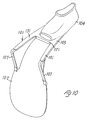
- a still further embodiment of a swimming flipper 101 is shown, which substantially includes a blade 102, a sole 103 and a shaped shoe 104. From the front part of the sole 103 project sideways two projecting elements 131. As one can see the projecting elements 131 form a wide, practically U-shaped, opening between them and the part of the sole 103 from which they project. To each of the lower surfaces of said projecting elements 131 are connected the first two ends of two supporting flexible rods 107, their other two ends being connected to the lower surface of the blade 102. Said blade 102, moreover, along the central zone of its root, is hinged to the sole 103 of the shoe 104 through a resilient joint 121, for instance of rubber or other elastomeric material.
- a resilient joint 121 for instance of rubber or other elastomeric material.
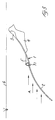
- These flexible rods 107 which in Fig. 10 are shown in the position of maximum extension at the beginning of the passive flippering, define the maximum rotation of the blade 102 with respect to the sole 103 of the shoe 104 and so the maximum deformation of the elastic joint 121: in fact the rotation arc described by the blade 102 as to the sole 103 shall not be too wide for not compromising the efficiency of the flipper 101 during the stage of the passive flippering.
- Said rods 107 can be molded integrally with the flipper 101 or positioned afterwards, and moreover, in case they are made of elastomeric material, they can include stroke limiting devices not shown.
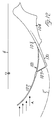
- Fig. 11 the flipper 101 is shown in a position corresponding to the beginning of the active flippering by the diver from down to up as to the water surface 6 and as one can see the blade 102 of the flipper 101 is very inclined as to said surface 6, advantageously much more than a blade 2'' of a conventional flipper.
- the lower surface of the blade 102 inclined in that way acts on the water mass, shown by the arrows A, in contact with it so to guarantee an optimal push forward to the diver and such inclination will be limited through the maximum extension of the rods 107.
- Fig. 12 is shown the flipper 101 of Fig. 11 in a position corresponding to the beginning of the passive flippering by the diver from up to down as to the water surface 6.
- the flipper 101 is practically parallel to the water surface 6.
- the upper surface or back of the blade 102 acts on the water mass, shown also here by the arrows A, in contact with it.
- a blade 2' of a conventional swimming flipper follows the rotatory movement of the sole 103 stiffly connected with it and this movement appears to be of little effectiveness from a dynamical point of view of the push forward as well as very hard for the diver.
- the blade 102 under the action of the water mass A which acts on its back, rotates around the elastic joint 121 of a certain angle, for instance 45°, and arranges itself in a position much more advantageous and effective for the flippering, being said rotation limited through the flexible rods 107 shown in the position of maximum extension.
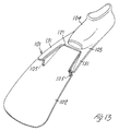
- Figs. 13 and 14 a further embodiment of the swimming flipper 101.
- the previously described flexible rods 107 have been replaced by flexible membranes 105, which are shown in the stand position (Fig. 13) and in the position of maximum extension at the beginning of the passive flippering (Fig. 14).
- Such membranes 105 can be made of elastomeric material and are connected on one side to the ends of the projecting elements 131 and on the other side to the edge of the surface of the blade 102.
- said elastic joint 121 and said flexible membranes 105 are obtained by injection molding of the same material forming the shoe 104, which can be for instance an elastomeric material, such as rubber or else.
Abstract
Description
- The present invention relates to swimming flippers, and in particular to flippers substantially consisting of a blade and a shaped shoe, said shaped shoe being made of an elastomeric material, rubber for instance, and said blade being made of a harder material, for instance of thermosetting resin with high values of hardness and mechanical resistance.
- It is known that while swimming the scuba diver substantially makes with each flipper, synchronously and continuously, two kinds of movement or flipping: a movement down-up with respect to the water surface, i.e. the active flipping, which begins with the flipper having a strong inclination wit respect to said surface, and a movement up-down, i.e. the passive flipping, which begins with the flipper being almost parallel to the water surface. Moreover, in the active flipping going upwards the lower surface of the flipper blade acts onto the water mass in touch with it and thus ensures a good forward thrust for the scuba diver, whereas in the passive flipping going downwards it is the upper surface or back of the blade which acts on the water mass in touch with it and substantially under it, said blade being located, as was said before, in an almost parallel position to the water surface, so that the forward thrust at this stage is rather limited.
- From US-A-3 171 142 a swimming flipper is known comprising a shoe provided with a sole to which a flexible blade is secured, and further comprising two pairs of abutment rods secured to said sole and disposed longitudinally each on one side of said blade for limiting the amplitude of the stroke of the blade. The described device is very difficult to be mounted on a swimming flipper.
- From US-A-2 343 468 a propulsion device for swimmers is known, which is very similar to the device of US-A-3 171 142 previously mentioned. This device is even more impractical than the device described in US-A-3 171 142.
- From US-A-3 256 540 a swimming flipper is known comprising a shoe element and a blade element. According to said prior art patent, the shoe element is hinged at the heel region to the blade element, and flexible tie means are provided between shoe and blade for limiting the angular stroke of the blade with respect to the shoe. Again, this device is very difficult to be realized.
- Aim of the present invention is then to realize a swimming flipper which overcomes the disadvantages of the prior art flippers making less hard for the diver and more effective from the dynamic point of view both the passive flippering and the active flippering, in particular guaranteeing to the flipper blade, at the beginning of the active flippering, a greater inclination as to the water surface of the one of the traditional flippers blades and then a more effective push forward.
- Such aim is reached according to an embodiment form of the present invention through a swimming flipper including a light shoe of relatively soft material with sole of stiffer material, provided in the front and on the side of at least two projecting elements, and a blade hinged in connection with its root to the sole of the light shoe in a zone between said projecting elements through two stroke-limiting elements, the whole in a way such that:
- in the passive flippering from up to down as to the water surface said blade rotates as to the light shoe sole under the action of the water mass in contact with the back of said blade, said rotation being limited by the maximum extension of said stroke-limiting elements;
- in the active flippering from down to up as to the water surface said blade rotates as to the light shoe sole under the action of the water mass in contact with the lower surface of said blade, said rotation being limited again by the maximum extension of said stroke-limiting elements.
- According to one embodiment of the present invention, the said stroke-limiting elements are in the form of flexible diaphragms.
- According to a further embodiment of the present invention, the said flexible diaphragms are replaced by blade support tie rods.
- According to still another embodiment of the present invention the said stroke-limiting elements are in the form of membranes or alternatively flexible rods for the supporting of the blade.
- The present invention will be better understood by means of the following description of some preferred embodiments of same, shown by way of non limiting examples in the enclosed drawings, where:
- Fig. 1 is a perspective view of a first of embodiment of the swimming blade of the present invention, with the flexible diaphragms in rest position, said diaphragms constituting a lateral link between the blade and the protruding elements of the shoe sole;
- Fig. 2 is a perspective view of the embodiment of Fig. 1 with said flexible diaphragms in the position of maximum extension;
- Fig. 3 shows the swimming flipper of Fig. 1 at the beginning of the active flipping down-up with respect to the water surface;
- Fig. 4 shows the flipper of Fig. 3 at the beginning of the passive flipping up-down with respect to the water surface;
- Fig. 5 is a perspective view of a second embodiment of the present invention with the blade support tie rods in rest position;
- Fig. 6 is a perspective view of the embodiment of Fig. 5 with the tie rods in the position of maximum extension;
- Fig. 7 shows the swimming flipper of Fig. 5 at the beginning of the active flipping going upwards wit respect to the water surface;
- Fig. 8 shows the flipper of Fig. 5 at the beginning of the passive flipping going downwards with respect to the water surface.
- Fig. 9 is a perspective view of another embodiment of the swimming blade of the present invention with the extensible rods, for the side support between the blade and the projecting elements of the light shoe sole, in standing position;
- Fig. 10 is a perspective view of the embodiment of Fig. 9 with the rods in one of the position of maximum extension, and precisely at the beginning of the passive flippering.
- Fig. 11 shows the swimming flipper of Fig. 9 at the beginning of the active flippering from down to up as to the water surface;
- Fig. 12 shows the flipper of Fig. 11 at the beginning of the passive flippering from up to down as to the water surface;
- Fig. 13 is a perspective view of still another embodiment of the present invention with the flexible membranes of the blade in stand position; and
- Fig. 14 is a perspective view of the embodiment of Fig. 13 with the membranes in one of the positions of maximum extension and precisely at the beginning of the passive flippering.
-
- With reference to the drawings, and with particular reference to Fig. 1, the
swimming flipper 1 shown comprises: ablade 2, made of thermosetting material with high mechanical resistance, a sole 3 usually made of the same material as theblade 2, and ashaped shoe 4 made of a soft elastomeric material, rubber for instance. From the front part of the sole 3 twoprotruding elements 31 extend laterally, whose ends partially cover the upper portion of theblade 2, so as to provide a shoulder surface for the upper surface of saidblade 2, as will be later shown with more details. As it is possible to observe, theprotruding elements 31 thus form a wide opening, almost U-shaped, with the portion of sole 3 from where they protrude. Each of the lower surfaces of saidprotruding elements 31 is linked to the first two ends of twoflexible diaphragms 5, the other two ends being linked to the lower surface of theblade 2. Saidblade 2, moreover, is hinged to the sole of theshoe 4 along the central area of its base by means of anelastic joint 21, made for instance of rubber or of any other elastomeric material. - These
flexible diaphragms 5, shown in Fig. 2 in their condition of maximum extension, determine the maximum rotation of theblade 2 with respect to the sole 3 of theshoe 4 and, therefore, the maximum deformation of theelastic joint 21. As a matter of fact, the rotation arch drawn by theblade 2 with respect to the sole 3 must not be too wide, so as not to compromise the efficiency of theblade 2 during the passive flipping. - According to a feature of the present invention, said
elastic joint 21 and saidflexible diaphragms 5 are obtained by injecting the material of theshoe 4, which can be for instance an elastomeric material, like rubber or other. - Fig. 3 shows the
flipper 1 of the present invention in a position corresponding to the beginning of the diver's active flipping down-up with respect to thewater surface 6 and, as can be observed, theflipper 1 is rather inclined with respect to saidsurface 6. The lower surface of theblade 2 acts onto the water mass, indicated by the arrows A, in touch with it, so as to ensure a good forward thrust for the scuba diver: in this situation, during said active flipping, theblade 2 moves integrally with the sole 3 of theshoe 4. As a matter of fact, its upper surface touches the hitting ends of theprotruding elements 31 of said sole, whereas the flexible diaphragms, linking theblade 2 and someprotruding elements 31, are in their rest position. - Fig. 4 shows the
flipper 1 of Fig. 3 in a position corresponding to the beginning of the diver's passive flipping up-down with respect to thewater surface 6. Theflipper 1, as can be observed, is almost parallel to thewater surface 6. In this case, during said passive flipping, the upper surface or back of theblade 2 acts onto the water mass, here again indicated by the arrows A, in touch with it. A blade 2' of a traditional swimming flipper follows the rotating movement of the sole 3, stiffly linked to said blade, and this movement shows a low efficiency from the dynamic point of view of the forward thrust, besides being rather hard for the scuba diver. According to the present invention, on the contrary, theblade 2, under the action of the water mass A acting on its back, rotates around theelastic joint 21 of a given angle, for instance 45°, and places itself in a position which is more advantageous and efficacious for the flipping movement, said rotation being limited by theflexible diaphragms 5, shown in their condition of maximum extension. - Fig. 5 and 6 show a further embodiment of the
swimming flipper 1. According to this embodiment the flexible diaphragms described above have been replaced by someflexible tie rods 7, which are shown in their rest position (fig. 5) and in their condition of maximum extension (Fig. 6).Such tie rods 7 can be of elastomeric material or not, and they are connected on one side to the ends of theprotruding elements 31 and on the other to the surface edge of theblade 2. Saidtie rods 7 can be moulded together with theflipper 1 or they can be positioned later; moreover, if they are made of elastomeric material, they can include some stroke limit controls, not shown. In this form of embodiment the contact area for the upper surface of theblade 2 corresponds to the inside lateral edges of theprotruding elements 31, placed near the base ofsaid blade 2, and not to their ends, as for the form of embodiment described above. Obviously, the use of saidtie rods 7 does not change the advantages of the use of theflexible diaphragms 5 according to the present invention. - The working of the
blade 1 according to this embodiment using thetie rods 7 instead of thediaphragms 5, as can be observed from Fig. 7 and 8, is very similar to what has been previously described for Fig. 3 and 4. Fig. 7 and 8 in fact show the action of the water mass A on theblade 2, respectively at the beginning of the diver's active flipping and at the beginning of the diver's passive flipping, with the advantageous inclination obtained by means of the maximum extension of thetie rods 7 supporting theblade 2 with respect to the inclination of a traditional blade 2'. The rotation of theblade 2 around theelastic joint 21 is limited by such maximum extension of theflexible tie rods 7, in the same way as for theflexible diaphragms 5. - In Fig. 9 a still further embodiment of a
swimming flipper 101 according to the present invention is shown, which substantially includes ablade 102, a sole 103 and ashaped shoe 104. From the front part of the sole 103 project sideways two projectingelements 131. As one can see the projectingelements 131 form a wide, practically U-shaped, opening between them and the part of the sole 103 from which they project. To each of the lower surfaces of said projectingelements 131 are connected the first two ends of two supportingflexible rods 107, their other two ends being connected to the lower surface of theblade 102. Saidblade 102, moreover, along the central zone of its root, is hinged to the sole 103 of theshoe 104 through aresilient joint 121, for instance of rubber or other elastomeric material. - These
flexible rods 107, which in Fig. 10 are shown in the position of maximum extension at the beginning of the passive flippering, define the maximum rotation of theblade 102 with respect to the sole 103 of theshoe 104 and so the maximum deformation of the elastic joint 121: in fact the rotation arc described by theblade 102 as to the sole 103 shall not be too wide for not compromising the efficiency of theflipper 101 during the stage of the passive flippering. Saidrods 107 can be molded integrally with theflipper 101 or positioned afterwards, and moreover, in case they are made of elastomeric material, they can include stroke limiting devices not shown. - In Fig. 11 the
flipper 101 is shown in a position corresponding to the beginning of the active flippering by the diver from down to up as to thewater surface 6 and as one can see theblade 102 of theflipper 101 is very inclined as to saidsurface 6, advantageously much more than a blade 2'' of a conventional flipper. The lower surface of theblade 102 inclined in that way acts on the water mass, shown by the arrows A, in contact with it so to guarantee an optimal push forward to the diver and such inclination will be limited through the maximum extension of therods 107. - In Fig. 12 is shown the
flipper 101 of Fig. 11 in a position corresponding to the beginning of the passive flippering by the diver from up to down as to thewater surface 6. As one can see theflipper 101 is practically parallel to thewater surface 6. In this case during the passive flippering the upper surface or back of theblade 102 acts on the water mass, shown also here by the arrows A, in contact with it. A blade 2' of a conventional swimming flipper follows the rotatory movement of the sole 103 stiffly connected with it and this movement appears to be of little effectiveness from a dynamical point of view of the push forward as well as very hard for the diver. According to one aspect of the present invention, on the contrary, theblade 102, under the action of the water mass A which acts on its back, rotates around theelastic joint 121 of a certain angle, for instance 45°, and arranges itself in a position much more advantageous and effective for the flippering, being said rotation limited through theflexible rods 107 shown in the position of maximum extension. - In Figs. 13 and 14 is shown a further embodiment of the
swimming flipper 101. According to this embodiment the previously describedflexible rods 107 have been replaced byflexible membranes 105, which are shown in the stand position (Fig. 13) and in the position of maximum extension at the beginning of the passive flippering (Fig. 14).Such membranes 105 can be made of elastomeric material and are connected on one side to the ends of the projectingelements 131 and on the other side to the edge of the surface of theblade 102. According to one aspect of the present invention said elastic joint 121 and saidflexible membranes 105 are obtained by injection molding of the same material forming theshoe 104, which can be for instance an elastomeric material, such as rubber or else. - The use of said
membranes 105 naturally let unchanged the advantages provided by therods 107 previously described and the functioning of theflipper 101 is completely like the one previously described with reference to the Fig. 11 and 12.
Claims (11)
- Swimming flipper comprising a shoe (4 ; 104) made of a relatively soft material and provided with a sole (3 ; 103) and with a blade (2; 102) made of a stiffer material characterized by the fact that said shoe (4 ; 104) is sidewise and frontwise provided with at least two protruding elements (31;131), said blade (2;102) being hinged to the sole (3;103) of the shoe (4;104) by means od a resilient joint element (21; 121) in an area between said protruding elements (31;131), and being further connected to said protruding elements (31;131) by means of two extensible stroke-limiting elements (5, 7; 105;107).
- Swimming flipper according to claim 1, in which said protruding elements (31) are suitable to hit against the upper surface of the blade (2), the whole so that:in the passive flipping up-down with respect to the water surface (6), said blade (2) rotates with respect to the sole (3) of the shoe (4) under the action of the water mass (A) touching the back of said blade (2), said rotation being limited by the maximum extension of said extensible elements (5, 7);in the active flipping down-up with respect to the water surface (6), said blade (2) moves integrally with the sole (3) of the shoe (4), said blade (2) being kept in position against the sole (3) of the shoe (4) by means of said contact of the ends of the protruding elements (31) against the upper surface of the blade (2) and said elements (5, 7) being in their rest position.
- Swimming flipper according to claim 1 or 2, in which said protruding elements (31;131) form, with the portion of sole (3;103) from where they protrude, a wide opening substantially U-shaped.
- Swimming flipper according to claim 1 or 2, characterised in that said extensible elements (5, 7; 105, 107) are flexible diaphragms (5, 105) connecting the lower surface of the protruding elements (31, 131) to the lower surface of the blade (2; 102) near its base.
- Swimming flipper according to claim 1 or 2, characterised in that said extensible elements (5, 7; 105, 107) are flexible tie rods (7; 107) connecting the ends of the protruding elements (31;131) to the edge of the blade (2;102) placed near said ends.
- Swimming flipper according to claim 5, characterised in that said tie rods (7;107) are made of elastomeric material and include some stroke limit controls.
- Swimming flipper according to claim 5, characterised in that said tie rods (7;107) are obtained by injection of the material of the shoe (4;104).
- Swimming flipper according to claim 1, characterised in that said resilient joint (21;121) is obtained by injection of the material of the shoe (4;104).
- Swimming flipper according to claim 1, characterized in that said extensible elements (105, 107) are flexible membranes (105) connecting the lower surfaces of the projecting elements (131) with the lower surface of the blade (102) near its root.
- A swimming flipper according to claim 1, characterized in that said extensible elements (105, 107) are flexible rods (107) connecting the ends of the projecting elements (131) with the edge of the blade (102) positioned near said ends.
- A swimming flipper according to claim 10, characterized in that said rods (107) are made of elastomeric material and include stroke limiting devices.
Applications Claiming Priority (4)
| Application Number | Priority Date | Filing Date | Title |
|---|---|---|---|
| ITGE980090 IT1304386B1 (en) | 1998-11-04 | 1998-11-04 | Swimming flipper comprises blade with sole made of a thermoset material with a high mechanical resistance and shaped shoe with protruding elements |
| ITGE980090 | 1998-11-04 | ||
| ITGE990008 IT1309455B1 (en) | 1999-01-20 | 1999-01-20 | Swimming flipper comprises blade with sole made of a thermoset material with a high mechanical resistance and shaped shoe with protruding elements |
| ITGE990008 | 1999-01-20 |
Publications (2)
| Publication Number | Publication Date |
|---|---|
| EP0998962A1 true EP0998962A1 (en) | 2000-05-10 |
| EP0998962B1 EP0998962B1 (en) | 2008-12-10 |
Family
ID=26330636
Family Applications (1)
| Application Number | Title | Priority Date | Filing Date |
|---|---|---|---|
| EP99120297A Expired - Lifetime EP0998962B1 (en) | 1998-11-04 | 1999-10-12 | Swimming flipper |
Country Status (5)
| Country | Link |
|---|---|
| US (1) | US6126503A (en) |
| EP (1) | EP0998962B1 (en) |
| JP (1) | JP4462678B2 (en) |
| DE (1) | DE69940046D1 (en) |
| TW (1) | TW420619B (en) |
Cited By (7)
| Publication number | Priority date | Publication date | Assignee | Title |
|---|---|---|---|---|
| EP1127589A1 (en) * | 2000-02-25 | 2001-08-29 | HTM SPORT S.p.A. | Swimming flipper |
| EP1398058A2 (en) * | 2002-09-13 | 2004-03-17 | Cressi-Sub S.p.A. | Differentiated rigidity swimming flipper with hydrodinamically designed fairings for the strap connections |
| US7537501B2 (en) | 2005-09-30 | 2009-05-26 | Cressi-Sub S.P.A. | Swimming fin with heel strap fastening buckle |
| ITTO20080971A1 (en) * | 2008-12-22 | 2010-06-23 | Technisub Spa | FIN FOR SWIMMING OR UNDERWATER ACTIVITIES |
| EP2055353A3 (en) * | 2007-09-28 | 2011-01-26 | Mares S.p.A. | Swimming flipper |
| IT201700037067A1 (en) * | 2017-04-04 | 2018-10-04 | Technisub Spa | FIN FOR SWIMMING OR UNDERWATER ACTIVITY |
| EP3922321A1 (en) * | 2020-06-11 | 2021-12-15 | Swunning Sàrl | Foot worn aquatic fin |
Families Citing this family (22)
| Publication number | Priority date | Publication date | Assignee | Title |
|---|---|---|---|---|
| US6482059B2 (en) | 1997-05-09 | 2002-11-19 | Mccarthy Peter T. | High efficiency hydrofoil and swim fin designs |
| US6449996B1 (en) * | 1998-03-19 | 2002-09-17 | Kawasaki Steel Corporation | Method of hot-rolling metal pieces |
| US6095879A (en) * | 1998-05-14 | 2000-08-01 | Mccarthy; Peter T. | Methods for creating consistent large scale blade deflections |
| US6843693B2 (en) * | 1998-05-14 | 2005-01-18 | Mccarthy Peter T. | Methods for creating large scale focused blade deflections |
| EP1132154A4 (en) * | 1999-09-16 | 2005-06-15 | Jfe Steel Corp | Method of hot-rolling metal pieces |
| US6394863B1 (en) * | 2000-10-11 | 2002-05-28 | Chien-Rung Chen | Fin with movable flap |
| US6520816B1 (en) * | 2002-04-10 | 2003-02-18 | Chia-Te Hu | Diving fins |
| US6758708B2 (en) * | 2002-06-28 | 2004-07-06 | Johnson Outdoors Inc. | Swim fin with energy storage and release system for improved angle of attack and water flow characteristics |
| AU2003249321B2 (en) * | 2002-07-19 | 2010-02-18 | Peter T. Mccarthy | Propulsion hydrofoils |
| JP2004065825A (en) * | 2002-08-09 | 2004-03-04 | Fuu Chia-Tee | Diving fin |
| US6881113B2 (en) * | 2002-12-06 | 2005-04-19 | R. Evan Smith | Propulsion device for use with swimmers |
| ITTO20060355A1 (en) * | 2006-05-16 | 2007-11-17 | Technisub Spa | FIN FOR SWIMMING |
| FR2952545B1 (en) * | 2009-11-18 | 2012-08-03 | Decathlon Sa | PALM EQUIPPED WITH A DISSYMMETRIC FLEXION BOAT |
| WO2014056066A1 (en) | 2012-10-12 | 2014-04-17 | Cetatek Holdings Inc. | Boot sole system and fin for same |
| US10675508B2 (en) | 2010-04-08 | 2020-06-09 | Cetatek Holdings Inc. | Coupleable fin apparatuses and boot toe bodies |
| AU2011238388B2 (en) | 2010-04-08 | 2014-10-30 | Cetatek Holdings Inc. | Flippers, boots, systems including same, and methods of using same |
| US10843043B2 (en) | 2018-01-04 | 2020-11-24 | Nature's Wing Fin Design, LLC | Hydrofoils and method |
| USD886223S1 (en) | 2019-02-08 | 2020-06-02 | Tyr Sport, Inc. | Swim fin |
| US10744374B1 (en) | 2019-04-08 | 2020-08-18 | Tyr Sport, Inc. | Swim fin with an upper portion having debossed regions and triple-bladed rails |
| KR102291618B1 (en) * | 2020-05-14 | 2021-08-18 | 안성수 | Inflatable life boat |
| US10905175B1 (en) | 2020-05-21 | 2021-02-02 | Tyr Sport, Inc. | Swimsuit with tension bands and reinforcement liners |
| CN114712821B (en) * | 2022-04-20 | 2023-05-09 | 西昌学院 | Swimming training device for physical education |
Citations (6)
| Publication number | Priority date | Publication date | Assignee | Title |
|---|---|---|---|---|
| DE1075997B (en) * | 1954-12-30 | 1960-02-18 | Ernst Langhans Dipl Ing | Swimming flippers to be attached to the foot |
| FR1208636A (en) * | 1958-09-04 | 1960-02-24 | Spirotechnique | Advanced swimming fin |
| US3082442A (en) * | 1958-09-04 | 1963-03-26 | Spirotechnique | Swimmer's fin |
| US3171142A (en) * | 1962-10-19 | 1965-03-02 | Auzols Pierre | Swimming shoe |
| US3256540A (en) * | 1963-04-04 | 1966-06-21 | Novelli Alberto | Device for surface and subaquatic swimming |
| US4209866A (en) * | 1978-10-02 | 1980-07-01 | Arthur D. Little, Inc. | Swim fin |
Family Cites Families (2)
| Publication number | Priority date | Publication date | Assignee | Title |
|---|---|---|---|---|
| FR2690348B1 (en) * | 1992-04-23 | 1994-07-08 | Roger Ours | FIN DEVICE, PARTICULARLY FOR WATER SPORTS, AND METHOD FOR MANUFACTURING SUCH A DEVICE. |
| IT1269122B (en) * | 1994-07-01 | 1997-03-21 | Cressi Sub Spa | FIN FOR SWIMMING AND ITS PRODUCTION PROCESS |
-
1999
- 1999-10-04 TW TW088117052A patent/TW420619B/en not_active IP Right Cessation
- 1999-10-12 EP EP99120297A patent/EP0998962B1/en not_active Expired - Lifetime
- 1999-10-12 DE DE69940046T patent/DE69940046D1/en not_active Expired - Lifetime
- 1999-11-01 JP JP31123399A patent/JP4462678B2/en not_active Expired - Fee Related
- 1999-11-02 US US09/431,775 patent/US6126503A/en not_active Expired - Lifetime
Patent Citations (6)
| Publication number | Priority date | Publication date | Assignee | Title |
|---|---|---|---|---|
| DE1075997B (en) * | 1954-12-30 | 1960-02-18 | Ernst Langhans Dipl Ing | Swimming flippers to be attached to the foot |
| FR1208636A (en) * | 1958-09-04 | 1960-02-24 | Spirotechnique | Advanced swimming fin |
| US3082442A (en) * | 1958-09-04 | 1963-03-26 | Spirotechnique | Swimmer's fin |
| US3171142A (en) * | 1962-10-19 | 1965-03-02 | Auzols Pierre | Swimming shoe |
| US3256540A (en) * | 1963-04-04 | 1966-06-21 | Novelli Alberto | Device for surface and subaquatic swimming |
| US4209866A (en) * | 1978-10-02 | 1980-07-01 | Arthur D. Little, Inc. | Swim fin |
Cited By (13)
| Publication number | Priority date | Publication date | Assignee | Title |
|---|---|---|---|---|
| US6290561B1 (en) | 2000-02-25 | 2001-09-18 | Htm Sport S.P.A. | Swimming flipper |
| EP1127589A1 (en) * | 2000-02-25 | 2001-08-29 | HTM SPORT S.p.A. | Swimming flipper |
| EP1398058A2 (en) * | 2002-09-13 | 2004-03-17 | Cressi-Sub S.p.A. | Differentiated rigidity swimming flipper with hydrodinamically designed fairings for the strap connections |
| EP1398058A3 (en) * | 2002-09-13 | 2004-06-09 | Cressi-Sub S.p.A. | Differentiated rigidity swimming flipper with hydrodinamically designed fairings for the strap connections |
| US7086916B2 (en) | 2002-09-13 | 2006-08-08 | Cressi-Sub S.P.A. | Differentiated rigidity swimming fin with hydrodynamically designed rearward shoe strap connection |
| US7901260B2 (en) | 2005-09-30 | 2011-03-08 | Cressi-Sub S.P.A. | Swimming fin with heel strap fastening buckle |
| US7537501B2 (en) | 2005-09-30 | 2009-05-26 | Cressi-Sub S.P.A. | Swimming fin with heel strap fastening buckle |
| EP2055353A3 (en) * | 2007-09-28 | 2011-01-26 | Mares S.p.A. | Swimming flipper |
| ITTO20080971A1 (en) * | 2008-12-22 | 2010-06-23 | Technisub Spa | FIN FOR SWIMMING OR UNDERWATER ACTIVITIES |
| IT201700037067A1 (en) * | 2017-04-04 | 2018-10-04 | Technisub Spa | FIN FOR SWIMMING OR UNDERWATER ACTIVITY |
| EP3922321A1 (en) * | 2020-06-11 | 2021-12-15 | Swunning Sàrl | Foot worn aquatic fin |
| WO2021249851A1 (en) | 2020-06-11 | 2021-12-16 | Swunning Sàrl | Foot worn aquatic fin |
| US11857844B2 (en) | 2020-06-11 | 2024-01-02 | Swunning Sàrl | Foot worn aquatic fin |
Also Published As
| Publication number | Publication date |
|---|---|
| JP2000140157A (en) | 2000-05-23 |
| US6126503A (en) | 2000-10-03 |
| TW420619B (en) | 2001-02-01 |
| DE69940046D1 (en) | 2009-01-22 |
| EP0998962B1 (en) | 2008-12-10 |
| JP4462678B2 (en) | 2010-05-12 |
Similar Documents
| Publication | Publication Date | Title |
|---|---|---|
| US6126503A (en) | Swimming flipper | |
| US5304081A (en) | Swim fin | |
| US7815477B2 (en) | Swimming flipper | |
| US6183380B1 (en) | Dual face golf putter | |
| US3411165A (en) | Swim fin | |
| US6290561B1 (en) | Swimming flipper | |
| EP1082975A1 (en) | Swimming flipper with controlled-flexibility blade | |
| US6053788A (en) | Swimming flipper | |
| US4838824A (en) | Swimming flipper | |
| WO1992005840A1 (en) | Swimming aid | |
| CA2631988A1 (en) | Ball stop for a lacrosse head | |
| US4300255A (en) | Foot flipper device | |
| CA2548803C (en) | Power toothbrush brushhead with fluid-directing member | |
| KR100664354B1 (en) | Soft Golf Club | |
| WO2006058849A1 (en) | Swimming flipper | |
| US5709575A (en) | Practice swim fin with perforations | |
| WO2007000394A1 (en) | Swim fin | |
| WO2014137375A2 (en) | Composite dive fin assembly | |
| JP2002306648A (en) | Putter for golf | |
| CN110548263A (en) | Flippers with secondary blade set | |
| KR200438351Y1 (en) | A golf shoes side sole | |
| SU1269793A1 (en) | Flipper | |
| ITGE990008A1 (en) | SWIMMING FIN. | |
| WO1998028052A1 (en) | A blade for an indoor bandy club | |
| GB1582036A (en) | Racket |
Legal Events
| Date | Code | Title | Description |
|---|---|---|---|
| PUAI | Public reference made under article 153(3) epc to a published international application that has entered the european phase |
Free format text: ORIGINAL CODE: 0009012 |
|
| AK | Designated contracting states |
Kind code of ref document: A1 Designated state(s): DE ES FR GR IT |
|
| AX | Request for extension of the european patent |
Free format text: AL;LT;LV;MK;RO;SI |
|
| 17P | Request for examination filed |
Effective date: 20000417 |
|
| AKX | Designation fees paid |
Free format text: DE ES FR GR IT |
|
| 17Q | First examination report despatched |
Effective date: 20040209 |
|
| RAP1 | Party data changed (applicant data changed or rights of an application transferred) |
Owner name: MARES S.P.A. |
|
| GRAP | Despatch of communication of intention to grant a patent |
Free format text: ORIGINAL CODE: EPIDOSNIGR1 |
|
| RBV | Designated contracting states (corrected) |
Designated state(s): DE ES FR GB IT |
|
| GRAS | Grant fee paid |
Free format text: ORIGINAL CODE: EPIDOSNIGR3 |
|
| GRAA | (expected) grant |
Free format text: ORIGINAL CODE: 0009210 |
|
| AK | Designated contracting states |
Kind code of ref document: B1 Designated state(s): DE ES FR GB IT |
|
| REG | Reference to a national code |
Ref country code: GB Ref legal event code: FG4D |
|
| REF | Corresponds to: |
Ref document number: 69940046 Country of ref document: DE Date of ref document: 20090122 Kind code of ref document: P |
|
| PG25 | Lapsed in a contracting state [announced via postgrant information from national office to epo] |
Ref country code: ES Free format text: LAPSE BECAUSE OF FAILURE TO SUBMIT A TRANSLATION OF THE DESCRIPTION OR TO PAY THE FEE WITHIN THE PRESCRIBED TIME-LIMIT Effective date: 20090321 |
|
| PLBE | No opposition filed within time limit |
Free format text: ORIGINAL CODE: 0009261 |
|
| STAA | Information on the status of an ep patent application or granted ep patent |
Free format text: STATUS: NO OPPOSITION FILED WITHIN TIME LIMIT |
|
| 26N | No opposition filed |
Effective date: 20090911 |
|
| PGFP | Annual fee paid to national office [announced via postgrant information from national office to epo] |
Ref country code: DE Payment date: 20090925 Year of fee payment: 11 |
|
| PG25 | Lapsed in a contracting state [announced via postgrant information from national office to epo] |
Ref country code: GB Free format text: LAPSE BECAUSE OF NON-PAYMENT OF DUE FEES Effective date: 20091012 |
|
| PG25 | Lapsed in a contracting state [announced via postgrant information from national office to epo] |
Ref country code: IT Free format text: LAPSE BECAUSE OF NON-PAYMENT OF DUE FEES Effective date: 20091012 |
|
| PGRI | Patent reinstated in contracting state [announced from national office to epo] |
Ref country code: IT Effective date: 20110616 |
|
| REG | Reference to a national code |
Ref country code: DE Ref legal event code: R119 Ref document number: 69940046 Country of ref document: DE Effective date: 20110502 |
|
| PG25 | Lapsed in a contracting state [announced via postgrant information from national office to epo] |
Ref country code: DE Free format text: LAPSE BECAUSE OF NON-PAYMENT OF DUE FEES Effective date: 20110502 |
|
| REG | Reference to a national code |
Ref country code: FR Ref legal event code: PLFP Year of fee payment: 17 |
|
| REG | Reference to a national code |
Ref country code: FR Ref legal event code: PLFP Year of fee payment: 18 |
|
| REG | Reference to a national code |
Ref country code: FR Ref legal event code: PLFP Year of fee payment: 19 |
|
| PGFP | Annual fee paid to national office [announced via postgrant information from national office to epo] |
Ref country code: FR Payment date: 20170913 Year of fee payment: 19 Ref country code: IT Payment date: 20170918 Year of fee payment: 19 |
|
| PG25 | Lapsed in a contracting state [announced via postgrant information from national office to epo] |
Ref country code: FR Free format text: LAPSE BECAUSE OF NON-PAYMENT OF DUE FEES Effective date: 20181031 |
|
| PG25 | Lapsed in a contracting state [announced via postgrant information from national office to epo] |
Ref country code: IT Free format text: LAPSE BECAUSE OF NON-PAYMENT OF DUE FEES Effective date: 20181012 |