EP0998315B1 - Dispositif electromagnetique d'injection transdermique - Google Patents
Dispositif electromagnetique d'injection transdermique Download PDFInfo
- Publication number
- EP0998315B1 EP0998315B1 EP98941360A EP98941360A EP0998315B1 EP 0998315 B1 EP0998315 B1 EP 0998315B1 EP 98941360 A EP98941360 A EP 98941360A EP 98941360 A EP98941360 A EP 98941360A EP 0998315 B1 EP0998315 B1 EP 0998315B1
- Authority
- EP
- European Patent Office
- Prior art keywords
- payload
- electromagnetic
- force generating
- generating mechanism
- conductive member
- Prior art date
- Legal status (The legal status is an assumption and is not a legal conclusion. Google has not performed a legal analysis and makes no representation as to the accuracy of the status listed.)
- Expired - Lifetime
Links
Images


Classifications
-
- F—MECHANICAL ENGINEERING; LIGHTING; HEATING; WEAPONS; BLASTING
- F41—WEAPONS
- F41B—WEAPONS FOR PROJECTING MISSILES WITHOUT USE OF EXPLOSIVE OR COMBUSTIBLE PROPELLANT CHARGE; WEAPONS NOT OTHERWISE PROVIDED FOR
- F41B6/00—Electromagnetic launchers ; Plasma-actuated launchers
- F41B6/003—Electromagnetic launchers ; Plasma-actuated launchers using at least one driving coil for accelerating the projectile, e.g. an annular coil
-
- A—HUMAN NECESSITIES
- A61—MEDICAL OR VETERINARY SCIENCE; HYGIENE
- A61M—DEVICES FOR INTRODUCING MEDIA INTO, OR ONTO, THE BODY; DEVICES FOR TRANSDUCING BODY MEDIA OR FOR TAKING MEDIA FROM THE BODY; DEVICES FOR PRODUCING OR ENDING SLEEP OR STUPOR
- A61M5/00—Devices for bringing media into the body in a subcutaneous, intra-vascular or intramuscular way; Accessories therefor, e.g. filling or cleaning devices, arm-rests
- A61M5/178—Syringes
- A61M5/30—Syringes for injection by jet action, without needle, e.g. for use with replaceable ampoules or carpules
Definitions
- the present invention relates to a device for injecting substances such as medicines into body tissues and more particularly to devices that inject dry substances into such tissues by means of electromagnetic energy.
- hypodermic needles are commonly used to inject liquid solutions or suspensions of a pharmaceutical agent into a patient's subcutaneous tissues.
- hypodermic syringes present notable shortcomings.
- the sharp hollow needles can cause injury to the patient as well as to the medical personnel administering the injection.
- the spent needles also are a potential source of infection or means for communication of disease, and consequently the used needles must be handled as hazardous medical waste.
- the injections are generally painful because of the needle's penetration of the patient's skin and the volume (e.g., 0.01 to 0.5 ml) of the injected fluid.
- administration by injection can require good eyesight and dexterity. This can be a problem for many patients who self-administer their injections.
- the overall process of administering an injection using the hypodermic syringe technique can be relatively costly, time-consuming and complex.
- Liquid jet injection systems have been developed as a needle-free alternative to the hypodermic syringe.
- a jet of liquid is ejected from an orifice at a high velocity that is capable of penetrating through tissue so as to deposit the medication subcutaneously.
- a liquid jet injection system may be less painful and may have a lower skill requirement for the user.
- the persons being injected also exhibit less psychological aversion to a liquid jet injection system than those being injected by means of a hypodermic syringe.
- the shelf life of liquid solutions or suspensions to be injected is most often less than that for dried powdered forms of medications or medicines. Consequently, some sensitive medications must be stored as dry powder and then mixed with a sterile liquid immediately prior to use.
- the process of preparing the solutions or suspensions for injection requires specialized skill and training as well as being time consuming and costly. Additionally, in less developed regions special preparations are usually required to provide an adequate source of sterile fluid and/or maintain the liquid solutions or suspensions.
- PCT Publication No. WO 94/24263 reports a certain needleless syringe using supersonic gas flow for delivery of dry particles including therapeutic agents.
- this needleless syringe at least one membrane is ruptured by a high-pressure gas source to generate a supersonic gas flow.
- the publication describes using a small 60-atmosphere reservoir of helium as the gas source.
- the rupturing of the membrane and the supersonic gas flow causes the medication particles to be accelerated to a velocity of about 800 to 1000 meters per second. It is also reported that the particles so accelerated penetrate a patient's skin to thereby deliver the medication. That described system has a number of shortcomings.
- the described syringe requires a high-pressure gas reservoir and release mechanism, or a mechanical equivalent, to generate the pressures required to establish supersonic flow conditions. Also, supersonic flow is noisy, and measures must be taken to reduce sound output. Thus, the PCT Application describes (e.g., at page 14) a silencer to receive the shockwave reflected back from the patient's skin. Despite the silencer, the device is very loud as a result of the fast release of high-pressure gas. Still further, because the system described in the PCT Application uses a pressurized gas source, the system faces regulatory barriers as with liquid jet injection systems that employ compressed gas.
- U.S. Patent Specification No. 5,294,850 discloses an electromagnetic accelerator arrangement including at least one stationary primary coil, and a movable arrangement including at least one movable secondary coil.
- the stationary primary coil is connected to the power source by conductors.
- the current in the secondary coil which is part of the moving projectile, is generated inductively by the changing field in the primary coil. This eliminates the need for conductors leading to the secondary coil, and fits in with the objective of using a secondary coil as part of a free-flying projectile.
- the invention features a transdermal injection device for injecting a therapeutic agent into a body through use of electromagnetic repulsive forces.
- dry powders, particles or substances can be injected through the skin of a body, e.g. human, animal or plant. Dry powders or particles or other materials can be administered whereby the material resides in subcutaneous tissue of the body.
- the dry substances being injected include, but are not limited to, solids, gels, liquids absorbed into porous solids, encapsulated liquids, powders or any form of material that can be injected at and/or accelerated to a high velocity.
- the particles and the like can be irregular in shape as well as being in predetermined forms or shapes, for example, spheres or arrows.
- the particles and the like can be uniform in size or vary over a prespecified range of sizes, for example, on the order of microns. Also, the number thereof can range from one to a million or more.
- a device of the invention uses electromagnetic repulsive forces between conductors carrying high anti-parallel pulsed currents to actuate a slingshot-like mechanism.
- This slingshot-like mechanism accelerates the material to be administered to a velocity sufficient for injection into a body.
- the material to be administered can be any of a variety of materials. particularly therapeutic agents such as insulin, antibiotics, analgesics, etc.
- the present invention includes an injection device for injecting a payload, particularly a dry powder, particles or the like, into and through the skin of a body, be it human. animal or plant.
- Electromagnetic repulsive forces between conductors carrying anti-parallel pulsed currents accelerate the payload to a sufficiently high velocity for injection into the body.
- anti-parallel is intended to describe the initial conditions of the current as it flows through the conductors. Specifically, that the current flow in one conductor is parallel to the flow in a second conductor but flowing in a different direction vectorally.
- the mechanism for generating the repulsive forces includes first and second conductive members that are initially disposed so that at least in a specified region the first and second conductive member are essentially parallel to each other.
- the payload is releasably attached or secured to the second conductive member in any of a number of ways so it is retained thereon while the repulsive forces are accelerating it.
- the repulsive forces are generated by passing a current through the first and second conductive members so the second conductive member is repulsively moved away from the first conductive member in at least the specified region whereat the first and second members are initially disposed parallel to each other.
- the payload also is attached or secured to the second member so it is released therefrom at an appropriate point during its acceleration.
- the force generated between the first and second conductive member in first approximation is proportional to the length in which first and second member are disposed parallel, proportional to the square of the current flowing through said members andinversely proportional to the distance between the members. It is therefore desired to dispose the members as close as possible together before actuation but avoiding electrical contact between the members.
- the members are electrically connected at one end and current is applied to the unconnected ends (e.g. loop shaped embodiments).
- a conductive metal member 20 having any geometric configuration that will, when subject to a high voltage, pulsed current, generate a force in a predetermined direction, which force accelerates a payload to the desired velocity for purposes of injection.
- the geometric configuration of a given slingshot mechanism 12 includes at least three attributes.
- the configuration of the slingshot mechanism suitably allows at least two opposing conductive members to be disposed as close as possible to each other with almost zero inductance.
- the configuration arranges the metal members so at least a portion of one metal member is essentially parallel to the other metal members over a pre-specified distance.
- the configuration of the slingshot mechanism suitably allows at least one of the metal members to move repulsively away from the other metal member.
- the configuration establishes anti-parallel current flow in opposing metal members in the pre-specified region so the at least one member is moved and accelerated by the electromagnetic fields created by the anti-parallel currents.
- the repulsive motion of the at least one metal member results in at least a portion of the metal member being accelerated in a predetermined direction.
- the configuration also allows a payload to be mechanically and releasably secured or attached thereto so it also is so accelerated. Additionally, such motion preferably occurs with minimum energy losses to the material.
- the electromagnetic force generating mechanism is shaped symetrically.
- the direction of acceleration is predetermined due to symmetry.
- Typical embodiments of such symetrical arrangements are shown in FIGS. 1, 3 and 15.
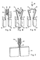
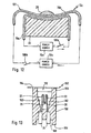
- FIGS. 1A-1C schematic views of one embodiment of a slingshot injection mechanism 12 that illustrates the principle embodied in an electromagnetic injection device 10 (FIG. 5) according to the present invention.
- FIGS. 10-12 for those components referred to herein that are not specifically shown on FIGS. 1A-1C.
- FIGS. 7-9 for further details regarding the payload 28, its composition and its attachment to the slingshot injection mechanism 12.
- reference is made to motion in an upwardly or upward direction however, this is not a limitation as the direction of motion is related to the orientation of the electromagnetic injection device 10 to the targeted area of the body.
- FIGS. 1A-1C illustrate the overall operational sequence of the first embodiment of a slingshot mechanism 12 from the pre-injection state or initial position, as illustrated in FIG. 1A, through acceleration of the payload 28, as illustrated in FIG. 1B, and separation of the payload 28 from the slingshot mechanism 12 for injection, as illustrated in FIG. 1C.
- a slingshot mechanism 12 including a conductive metal member 20, that is bent or shaped into a narrow "M" shape.
- the two outer arms 22 thereof are bonded or electrically interconnected to input power leads 24.
- the inner portion of the "M" shape includes two inner arms 23 that are interconnected by an arcuate or bent cup member 25 to form a sling 26.
- the payload 28 is disposed in the bent cup 25 of the sling 26.
- the outer and inner arms 22, 23 also are mechanically and electrically interconnected by means of curved members that essentially form a hinge point for adjacent inner and outer arms.
- the outer arms are first conducting members and the inner arms are second conducting members to which the payload is attached.
- a current pulse is introduced into the slingshot mechanism 12 via the input power leads 24.
- the current in each outer arm 22 of the slingshot mechanism 12 is anti-parallel to that in an adjacent inner arm 23. This causes mutual repulsion between adjacent inner and outer arms 22, 23 so they move apart from each other as illustrated in FIG. 1B.
- the bent cup member 25, and correspondingly the payload 28 is accelerated in an upwardly direction, as also illustrated in FIG. 1 B. In this way, the motion of the sling 26 transfers kinetic energy developed by the repulsive motion of the inner and outer arms 22, 23 to the payload 28.
- Further motion of the slingshot mechanism 12 can be best understood by modeling it as a hinged rigid body. Because of mutual repulsion, the outer and inner arms 22, 23 continue to move apart until the sling 26 is straightened. At that time, the payload 28 and the relative center of the sling 26 reach their maximum velocity. As the sling 26 passes through the straight position, it starts to slow down. The reduced velocity of the sling 26 causes the payload 28 to separate therefrom as shown in FIG. 1C. The payload 28 continues traveling towards the targeted area of a body. The maximum velocity attained by the payload 28 is sufficient so the payload can penetrate the skin of a body and comes to a rest in the subcutaneous tissues.
- the employed symmetric electromagnetic force generating mechanism has the advantage that the direction of acceleration of the payload is well defined.
- the current pulse introduced into the slingshot mechanism 12 preferably is a high current pulse, e.g. on the order of thousands of amperes, over a very short duration, e.g. on the order of microseconds. In this way, the current pulse can pass through the outer and inner arms 22, 23 before the arms have moved apart repulsively due to the electromagnetic fields generated by the current pulse.
- the peak current of the current pulse is in the range of 6,000 to 20,000 amperes.
- the pulse duration is 1 microsecond or less, and the voltage is in the range of 1,000 to 4,000 volts.
- the duration, current and voltage of the current pulse is selected so the maximum velocity attained by the dry substance being injected is sufficient to penetrate the skin of the body or organism and achieve the desired penetration into the tissues thereof.
- the amount of penetration, and correspondingly the maximum velocity required to be attained. is dependent upon a number of factors including the density, size, orientation and shape of the dry substance or that comprising the dry substance (e.g., particle size).
- a payload of 0.5 milligrams consisting of particles in about the 20 micron range typically would penetrate the skin and reside in the subcutaneous tissues of a body, if accelerated to a maximum velocity of 800 meters per second or more.
- maximum velocities higher or lower than 800 meters per second can be utilized to achieve the desired penetration for a given size, shape and density of a particle.
- the conductive metal member 20 can be made from any of a number of conductive materials and have any thickness provided that the resultant product can accelerate the payload to attain the desired or required velocity for injection of the payload into a patient.
- the materials and thickness selected are sufficient to maintain structural integrity of the slingshot mechanism 12, in particular the metal member 20, following the introduction of the current pulse in the metal member and creation of the repulsive electromagnetic fields to accelerate the payload 28.
- the thickness or configuration of each outer arm 22 can be adjusted to be more resistant to local bending stresses caused by the repulsive force.
- each outer arm 22 can be provided with a U-shape or the outer arms made thicker than the inner arms 23.
- the metal member 20 and input leads are made from aluminum.
- the metal member preferably is a ribbon having a thickness of about 0.1-0.2 millimeters and a width on the order of 1-2 millimeters.
- the outer and inner arms 22, 23 are initially spaced parallel to each other in a pre-specified region on the order of 2-5 millimeters in length. Additionally, the outer and inner arms 22, 23 are spaced as close as possible to each other without electrically shorting out across the arms. In particular embodiments, the air gap between the outer and inner arms 22, 23 is about 0.025 to about 0.1 millimeter in at least the pre-specified region.
- an insulating film such as a polymer film is disposed at least between the outer and inner arms 22, 23 so the arms are spaced from each other by the thickness of the film. This insulating film also can be laminated along one surface of the metal member 20 so the film is disposed between the outer and inner arms 22, 23.
- FIG. 2 an alternate embodiment of a slingshot mechanism 12a to that shown in FIGS. 1A-1C.
- the conductive metal member 20a includes an intermediate portion 27, including two electrical leads that are electrically and mechanically interconnected to the outer arms 22 and the input leads 24.
- the alternate embodiment functions in a similar fashion as that described hereinabove the slingshot mechanism 12 of FIGS. 1A- 1C.
- FIGS. 3A-3C there are shown cross-sectional views of a second embodiment of a slingshot injection mechanism 12b that illustrate the principle embodied in an electromagnetic transdermal injection device 10 according to the present invention.
- FIGS. 10-12 for components referred to herein that are not specifically shown on FIGS. 3A-3C.
- FIGS. 7-9 for further details regarding the payload 28, its composition and its attachment to the slingshot injection mechanism 12.
- FIGS. 3A-3C illustrate the overall operational sequence of the second embodiment from the initial position, as illustrated in FIG. 3A, through acceleration of the payload 28, as illustrated in FIG. 3B, and separation of the payload 28 from the slingshot mechanism 12b, as illustrated in FIG. 3C.
- the second embodiment of the slingshot mechanism 12b includes a conductive metal member 20b and a support block 30.
- the metal member 20b includes an arcuate top portion 32 and two arcuate bottom portions 34, which are interconnected by two curved portions 36. At least a portion of the top surface 38 of the support block 30 is curved to complement the arcuate shape of the bottom portions 34 and includes a through aperture for the conductor leads 40 extending from the bottom portions.
- the conductor leads 40 are electrically interconnected to the input power leads 24 as illustrated in FIGS. 1-2.
- the conductive metal member 20b lies in a dished slot formed in the support block 30.
- a current pulse is introduced into the slingshot mechanism 12b via the input leads 40. Because of the antiparallel currents in the top and bottom portions 32, 34, the top and bottom portions are mutually repulsed from each other, as described hereinabove. The motion of the bottom portions 34, however, is essentially restrained by the support block top surface 38. Thus, the mutual repulsive forces mainly cause the top portion 32 to move away from the bottom portions 34 as illustrated in FIG. 3B and thereby accelerate the payload 28. In this way, the slingshot mechanism top portion 32 transfers kinetic energy to the payload 28.
- the relative center of the top portion 32 reaches a maximum velocity and thereafter velocity reduction begins.
- the payload 28 separates from the top portion as shown in FIG. 3C.
- the maximum velocity attained by the payload 28 due to the motion of the top portion 32 is sufficient so the payload can penetrate the skin of a body and come to rest in the subcutaneous tissues thereof.
- the initial curved configuration of the metal member 20b is beneficial in this regard because it enables the metal member to accelerate with minimum bending energy loss and thus, more of the repulsive energy is directed to accelerating the payload. Bending losses are minimized because the bottom portions 34 are being restrained and supported by the support block 30 and because the metal member 20b essentially unrolls from the initial position to the release position without large deformations at the hinge points.
- FIG. 3 is a symmetrical one in terms of this invention because the first members (34) comprise two bottom portions of the same shape and the second member (32) can be viewed as two identical portions meeting in the middle.
- the payload is attached to the second conductive member in the center region (near the plane of symmetry) the direction of movement is clearly defined.
- the support block 30 is constructed from materials that can withstand the structural load imposed by the repulsive forces and restrain the bottom portions 34 from further motion.
- the materials of the support block are non-conductive and non-magnetic.
- the support block is made from ceramics or plastics such as thermoplastics or thermosetting plastics.
- an insulating film 37 such as plastic polymer film, is disposed between and electrically isolates opposing surfaces of the top portion 32 and the bottom portions 34 of the conductive metal member 20d.
- the insulating film 37 also continues along the entire length of the opposing surfaces so as to electrically isolate the two electrical leads that extend outwardly from an aperture in the support block 30.
- the insulating film 37 is applied or laminated to the metal material from which the metal member 20d is formed.
- any one of a number of techniques or means known to those skilled in the art can be used to separate and electrically isolate the opposing surfaces of the metal conductive member 20d.
- lamination of one surface is illustrated, it is within the scope of the instant invention for more than one surface to be laminated or coated with an insulating film.
- the leads 33 are interconnected to the current and voltage source by means of two clamping electrodes 35 that clamp the leads together.
- These clamping electrodes 35 can be included as part of the slingshot module 110 or the plug connection 112 (FIGS. 11-13) so they removably receive the leads of the slingshot mechanism.
- the alternate embodiment functions in a similar fashion as that described hereinabove for the slingshot mechanism 12b of FIGS. 3A-3D.
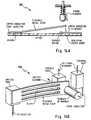
- FIG. 5 a third embodiment of a slingshot mechanism 12c of the instant invention including a conductive metal member 20c, and a support block 30c.
- a conductive metal member 20c for acceptable materials and construction details for the conductive metal member 20c, the parameters or characteristics of the injected pulse current and the materials for the support block 30c.
- FIGS. 7-9 for further details regarding the payload 28, its composition and its attachment to the slingshot injection mechanism 12.
- the metal member 20c includes a loop 50 having first and second arms 52, 54 that are mechanically and electrically interconnected to each other by means of a curved portion and which are each mechanically and electrically interconnected to the input power leads 24.
- the payload 28 is disposed at about the mid-point of the first arm 52.
- the support block 30c is disposed so one side 31 thereof abuts one side of the second arm 54, preferably this side 31 of the support block is in close contact with this side of the second arm.
- the opposing side 33 of the support block 30c is in close contact with another non-moving surface of the slingshot module 100 or in a pocket formed in one of the input leads 24, as illustrated in FIG. 5.
- the housing 150 for the slingshot module 100 can be configured so the support block is integrally formed as part of the module housing.
- a pulsed current is introduced into and passed through the metal member 20c, thereby creating repulsive forces that move the first and second arms 52, 54 apart from each other.
- the support block 30c essentially restrains the repulsive motion of the second arm 54 so only the first arm 52 moves in any significant fashion in predetermined direction 56.
- the payload 28 is thus accelerated and moved in this direction in a similar fashion as that described for the top portion 32 of the second embodiment (FIGS. 3A-3C).
- the payload 28 is accelerated to its maximum velocity and separated from the first arm 52 so it can penetrate the skin of a body and come to rest in the subcutaneous tissues thereof.
- the embodiment of FIG. 5 is an asymmetrical one. The direction of movement of the payload is clearly dependent on the resilent forces of first (52) and second member (54) and the direction of movement has therefore to be determined experimentally.
- FIGS. 6A-6B a fourth embodiment of a slingshot mechanism 12e of the instant invention including a conductive metal member 20e, and a support block 30e.
- a conductive metal member 20e for acceptable materials and construction details for the conductive metal member 20e, the parameters or characteristics of the injected pulse current and the materials for the support block 30e.
- FIGS. 7-9 for further details regarding the payload 28, its composition and its attachment to the slingshot injection mechanism 12e.
- the metal member 20e includes a top segment 60 that is disposed opposite two bottom segments 62.
- the top and bottom segments 60,62 are structurally and electrically interconnected to each other by means of two corrugated or fan folded sides 64 so as to for a box like structure having flexible sides.
- the input leads 68 interconnected to the bottom segments 62 are electrically separated from each other by means of an insulating member 66 that can be an insulating polyester film as hereinabove described.
- the outside surface and/or the opposing surface of the metal member segments 60, 62, 64 can be coated with an insulating film as shown in FIG. 4.
- the corrugated sides 64 are compressed downwardly in direction 67 so the top and bottom portions 60,62 are spaced about 0.025 to about 0.1 millimeters apart.
- a current pulse is passed through the metal member 20e via the input leads 68.
- the bottom segments 62 remain essentially stationary due to the presence of the support block 30e.
- the top segment 60 is electromagnetically and repulsively moved away from the bottom segments 62.
- the corrugated sides 64 also contribute to the repulsive motion of the top segment 60 because of the anti-parallel current flow through opposing corrugations in the corrugated sides.
- the payload 28 will separate from the top segment 60 as is shown in FIG. 6A.
- FIGS. 7-9 There is shown in FIGS. 7-9 three exemplary mechanisms and techniques for packaging the payload 28 so it is releasably attached or secured to a portion of the slingshot mechanism 12 and more specifically to the metal member 20 of such a mechanism.
- the mechanisms and techniques described herein are not exhaustive of all the possible mechanisms and techniques for holding the payload during its acceleration phase to a member and then controllably releasing it at some point when the payload has attained the maximum velocity desired for injection. As such it is within the scope of the instant invention to include all such other mechanisms, techniques or methods.
- the payload 28 comprises dry substances or the like that can be injected through the skin of a body or organism whereby the injected material resides in the subcutaneous tissue of the body or organism.
- the dry substances being injected include, but are not limited to, solids, gels, liquids absorbed into porous solids, encapsulated liquids, dry powder, particles or any form of material that can be injected at, and/or accelerated to. a high velocity.
- the particles and the like can be irregular in shape as well as being in predetermined forms or shapes.
- the particles can be spherical or arrow shaped or a mixture thereof.
- the particles and the like can be uniform in size or vary over a prespecified range of sizes. Also, the numbers thereof can range from one to a million or more.
- the active material being injected includes therapeutic agents such as antibiotics, insulin, proteins and analgesics.
- therapeutic agents such as antibiotics, insulin, proteins and analgesics.
- the material being administered to include other injectable substances including for example DNA.
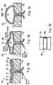
- FIGS. 7A-7B there is shown a cross sectional view of part of an exemplary slingshot mechanism 12 to illustrate one mechanism or technique for releasably securing a payload to the slingshot mechanism.
- an enclosure is secured to the moving arm or portion of the conductive metal member 20 of the slingshot mechanism 12 using an adhesive or the like.
- the enclosure 200 includes one or more breaklines 202, slits, areas of localized thinning or the like, which are designed to fail when subject to certain loads and thereby open up the enclosure.
- FIG. 7A when the slingshot mechanism is in its initial, non-accelerated condition, the enclosure is sealed and the payload 28 is retained therein.
- the enclosure 200 and correspondingly the payload 28 therein is accelerated in the fashion described hereinabove.
- the inertia of the payload and/or the deformation of the metal member 20 causes each breakline to open thereby releasing the payload 28 for injection as shown in FIG. 7B. Once released, the payload 28 continues onto the targeted area of the body or organism.
- FIGS. 8A-8B there is shown a cross sectional view of part of an exemplary slingshot mechanism 12 to illustrate a second mechanism or technique for releasably securing a payload to the slingshot mechanism.
- a coating 210 of an adhesive mastic or the like is applied to the moving arm or portion of the conductive metal member 20 of the slingshot mechanism 12.
- the material constituting the payload 28 such as the particles or powder, is applied to the exposed surface of the coating 210, as shown in FIG. 8A, so they are retained thereon when the slingshot mechanism is in its initial, non-accelerated condition.
- the payload 28 separates from the coating 210 as is shown in FIG. 8B.
- FIGS. 9A-9C there is shown a cross sectional view of part of an exemplary slingshot mechanism 12 to illustrate a third mechanism or technique for releasably securing a payload to the slingshot mechanism.
- a pouch 200 is secured to the moving arm or portion of the conductive metal member 20 of the slingshot mechanism 12 using an adhesive, by heat bonding the material to the metal member or the like.
- the pouch 200 includes one or more rupture zones 222 or lines, which are designed to fail, when subject to certain loads and thereby rupturing or opening the pouch.
- FIG. 9B when the slingshot mechanism is in its initial, non-accelerated condition, the pouch 200 is sealed and the payload 28 is retained therein.
- the pouch 200 and correspondingly the payload 28 therein is accelerated in the fashion described hereinabove.
- the inertia of the payload 28 and/or the deformation of the metal member 20 causes each rupture zone 222 to fail thereby releasing the payload 28 for injection as shown in FIG. 9C.
- the payload 28 continues onto the targeted area of the body or organism.
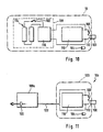
- FIG. 10 A block diagram for one embodiment of an electromagnetic injection device 10 according to the present invention is shown in FIG. 10.
- the injection device 10 includes a ready light 104 an actuator switch 106, a power supply 108, a capacitor 110 and a plug connection 112 that electrically interconnects a slingshot module 100 and the electrical leads to the capacitor 110 via the actuator switch 106.
- the injection device 10 is handheld and all the components are located in a single housing having, for example, outside dimensions on the order of about 175 millimeters long and 65 millimeters wide.
- the loading, use and operation of such an injection device 10 is simple and does not require specialized training or particular knowledge of, for example, human or animal physiology.
- the capacitor 110 is a high voltage, low inductance capacitor, such as that manufactured by Cornell Dubilier for exploding foil initiators, which can be charged to about 5 joules of stored energy.
- the capacitor has a capacitance of about 0.2-4.0 microfarads, more particularly about 1 microfarad, an inductance of about 1-10 nanohenries, more particularly about 2.5 nanohenries, and an output voltage in the range of from about 1,000 to 4,000 volts.
- the capacitor 110 also is capable of generating high currents on the order of 6,000 to 20,000 amperes during a discharge cycle.
- the capacitor 110 is interconnected to the ready light 104 using any one of a number of techniques known in the art so the ready light is lit when the capacitor has been-charged to the minimum energy level required for firing a slingshot mechanism 12.
- the ready light 104 is any of a number of lights known in the art for providing such visual signals including but not limited to LEDs, LCDs and xenon bulbs.
- the actuator switch 106 is any one of a number of mechanical types of switches such as a common SPST toggle switch, or any other switches known in the art, including but not limited to solid state switches and triggered sparked gap switches. In particular, switches that can be repetitively opened and closed in the presence of large voltages, on the order of kilovolts, and that will pass the required currents over a discharge cycle.
- the actuator switch 106 is a mechanical switch with metallic contacts having a 20 ampere rating that has been observed to generally show little damage after multiple shots in the 5,000 to 10,000 ampere pulse current range.
- Such switches also allow the output voltage to rise to the desired voltage on the order of tens of nanoseconds, which is adequate for a current pulse length on the order of a microsecond.
- the actuator switch 106 preferably allows multiple shots, it is within the scope of the present invention for the injection device 10 to be configured with a single-use set of switch contacts as part of the slingshot module 100. In this way, the switch contacts would be replaced each time the slingshot module 100 is replaced. Schematic views of some exemplary mechanical switches 106 are shown in FIGS. 14A-14B. As also indicated below, the actuator switch 106 is preferably selected so as to minimize inductive energy losses.
- the plug connection 112 includes a housing and, disposed therein, any one of a number of electrical mating connections that electrically interconnect to the input leads 24 of the slingshot module 100 and which has the capability to repetitively pass the required pulse currents without failure.
- the housing of the plug connection 112 is configured to removably receive and support the slingshot module 100 for injection of the payload.
- the plug connection housing is configured so the slingshot module is easily inserted into and removed therefrom without special tools or equipment.
- the housing of the plug connection 112 is made from a non-conductive and non-magnetic material such as plastic to minimize inductive energy when firing the slingshot mechanism 12.
- the plug connection housing is formed along with the housing of the injection device 100 so as to yield a unitary structure. Alternatively, the plug connection housing is appropriately secured to the housing of the injection device 10.
- the electrical lines or leads between the capacitor and the slingshot module 100 are of a length and design that minimizes inductive energy losses.
- the capacitor 110, the actuator switch 106 and the plug connection 112 are selected so as to minimize inductive energy losses when firing the slingshot mechanism 12.
- the electric circuit forming the current discharge path from the capacitor 110 to the slingshot mechanism 12 is designed, and the components thereof (e.g., the capacitor) are selected, so the current to the slingshot mechanism 12 peaks while the portions of the conductive metal member 20 that are to be subjected to the electromagnetic repulsive forces are close to their initial position, as shown in FIGS. 1A, 2, 3A, 4 and 5, and moving slowly. In this way, the current exerts the maximum impulse (i.e., force integrated over time) on these portions of the conductive metal member 20.
- the power supply 108 can be any one of a number of sources of electrical power known to those skilled in the art which can develop the voltages and currents required to charge the capacitor 110 in a reasonable time interval, for example 10 seconds or less.
- the power supply 108 preferably comprises an on/off switch 102, a DC power source 114 and a high voltage DC to DC converter 116.
- the DC to DC converter 116 is an electrical circuit configured using any one of a number of techniques known in the art for repetitively and reliably charging the capacitor 110 to the required capacity using a low voltage DC power source.
- the capacitor 110 can be charged from an AC power source and the converter appropriately configured electrically to convert AC voltage and current to the DC voltage and current required for charging the capacitor.
- the DC power source battery source 114 is a plurality of batteries, for example AA alkaline batteries, in series connection.
- the DC power source can be any of a number of systems, e.g. a system that comprises one or more batteries and be any type of battery for example a C-cell battery.
- the batteries can be connected in series or parallel.
- the type of battery can be alkaline, NiCd, nickel metal hydride, or any of a number of known types of batteries.
- the battery selected for use preferably is conveniently available to the user and has sufficient capacity so the capacitor 110 can be charged tens of times (e.g., 50 times) before the batteries comprising the DC power source 114 would have to be replaced by the user.
- the on/off switch 102 is any one of a number of switches known in the art, such as a Mini Mike Miniature Snap Action Slide switch as manufactured by ITW Switches.
- the on/off switch 102 preferably is disposed between the DC power source 114 and the DC to DC converter 116 so the switch interrupts low voltages and currents.
- the on/off switch 102 it is within the scope of the instant invention for the on/off switch 102 to be located between the power supply 108 and the capacitor 110 so as to interrupt the voltage and currents being outputted by the power supply.
- FIG. 11 a block diagram of a second embodiment of an injection device 10b including a handheld injection unit 120, a remotely located power supply 108a and an electrical cable 122 interconnecting the power supply 108a and the handheld injection unit 120 for charging of the capacitor 110.
- the handheld unit 120 includes the above described on/off switch 102, ready light 104, actuator switch 106, capacitor 110 and plug connection 112 that electrically interconnects the slingshot module 110 and the electrical leads to the capacitor 110 via the actuator switch 106.
- the power supply 108a is configured to supply the voltages and currents required for changing the capacitor 110 to the required energy/capacity.
- the power supply 108a is an AC to DC converter that is plugged into an electrical wall or floor type of socket or outlet.
- the power supply can be a variety of systems, e.g. a DC battery pack, for example a battery pack belt used in the video recording industry, with a DC to DC converter 116 as hereinabove described to supply the required voltages and currents.
- the DC to DC converter 116 is included in the handheld unit 120 so only low voltages and currents are being supplied over the cable 122.
- the cable 122 is any one of a number of known electrical cables that can safely and reliably handle the voltages and currents being supplied.
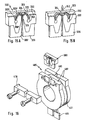
- FIG. 12 a schematic view of a third embodiment of an electromagnetic injection device 10c according to the instant invention. Also illustrated is another embodiment of a slingshot mechanism 12f.
- This slingshot mechanism 12f includes a first conductive metal member 70a and a second conductive metal member 70b that are initially disposed parallel to each other over a pre-specified region as hereinabove described.
- the first and second metal members 70a,b are arcuate and arranged so as to lie in a convex cavity in a support block 30f.
- the payload 28 is disposed at about the low point, and correspondingly at about the midpoint, of the second member 70b.
- the first member 70a is essentially stationary when a high energy current pulse is passed through it, because of the support block 30f, and the second member 70b moves repulsively away from the first member thereby accelerating the payload 28.
- the first and second metal members 70a,b are each fed by a separate power source 72a,b.
- Each of these power sources 72a,b includes the functional components (e.g., on/off switch 102, capacitor 110) hereinabove described in connection with FIGS. 10-11 used to output a high energy current pulse.
- the device also is configured so as to provide synchronous current pulses to each of the first and second metal members 70a,b so the second member 70b will repulsively move away from the first member and thereby accelerate the payload releasably attached or secured to the second member.
- the first and second metal members 70a, b are electrically interconnected to a single power source although they are not looped together as in other described slingshot mechanism embodiments.
- FIG. 12 Even the embodiment shown in FIG. 12 is a symmetrical one in terms of this invention.
- the payload is attached to a center portion of the second conductive member (70b) and when currents are applied to the first and second members the force applied to the payload (28) is symmetrical with regard to a plane of symmetry vertical to the drawing plane
- the foregoing electromagnetic injection devices 10, 10a are described as having a one capacitor 110, this is not a limitation. It is within the scope of the instant invention for such an injection device to include two or more capacitors, connected electrically in series or in parallel, to develop the desired voltage and current pulses. Also, the injection device of the subject invention includes any injection device that embodies the features of the instant invention regardless of the specific arrangement of individual components. For example, a handheld injection unit can be electrically connected to an AC power source, and the handheld unit include an AC to DC converter to convert the AC voltage and currents to the voltages and currents required for charging the capacitor. Also, it is within the scope of the instant invention, for such an injection device to be configured as a one shot type of device that is disposed of after use or an injection.
- the slingshot module includes a housing 150, slingshot mechanism 12, and cover member 154 that seals an aperture 152 in one end of the housing.
- the cover member 154 can be a foil such as polyester or Mylar that is removably secured to the housing 150.
- the cover member 154 is a polyester film with an ethylene vinyl acetate adhesive coating, such as the Scotch Pack Heat Sealable Lid Film manufactured by 3M, that is heat sealed to the housing 150.
- the cover member 154 in conjunction with the housing 150 seals the aperture 152 through which the payload 28 is expelled so the payload does not become contaminated or spoiled.
- the housing 150 preferably is made of a material that is non-conductive and nonmagnetic including, for example, thermoplastics such as polyesters, polycarbonates and ABS, and thermosetting plastics such as phenolics and epoxies.
- the housing material selected also should not react with or increase the risk of contamination to the payload 28.
- the slingshot mechanism 12 is disposed in the module housing 150 so the direction of acceleration for the payload 28 is essentially congruent with the axis of the housing aperture 152. Thus, when the slingshot mechanism 12 is actuated or fired by means of the pulsed current, the payload 28 is expelled through this aperture 152. To make the injection process easier.
- the housing preferably is designed so the distance between the initial position of the payload 28, for example, in the bent cup portion 25, and the end surface 156 of the housing, at which the cover member 154 is secured, is the desired distance between the payload and the skin of the area being targeted for injection. It should be recognized that the module 100 is not limited to the specific slingshot mechanism being illustrated and that it is within the scope of the instant invention for the slingshot module 100 to include any of the slingshot mechanisms described or referred to herein.
- a recess 160 is provided in the opposite end 158 of the module housing 150, in which are exposed the input leads 24 to the slingshot mechanism 12. This end 158, the recess 160 and positioning of the input leads 24 are arranged and configured so as to mate with and be removably received by the plug connection 112 of the injection device 10, 10a.
- the housing 150 also is constructed to support the slingshot mechanism 12 so it is maintained in the appropriate alignment for injection.
- the housing includes two interior sloping surfaces 162 that are disposed outboard of the outer arms 22.
- the sloping surfaces 162 are configured so as to function like a support block and restrain the motion of the outer arms 22 so they do not depart from the desired configuration during acceleration of the payload. It should be recognized that it is within the scope of the instant invention for the interior surfaces of the housing to be configured to restrain certain motion of the conductive metal member 20 as herein described or configured so as not to restrain any such motion.
- injection devices of the instant invention can be best understood from the following discussion and with reference to the figures hereto and the foregoing discussion.
- the injection process is described below as being in a specific sequence. it is within the scope of the invention for the described actions to be in any sequence that will result in the injection of a payload of therapeutic compounds into a body.
- the below-described process involves the injection of a therapeutic compound payload into a body, it is within the scope of the described method or process to inject any dry substance. as herein described, into a body or organism.
- the manufacturer preloads, with a specified therapeutic compound or the like and at a desired dosage, in sterile packaging each slingshot module 100.
- the slingshot mechanism 12 it is within the scope of the instant invention for the slingshot mechanism 12 to be loaded in situ prior to use.
- the pre-loaded slingshot module 100 having the required dosage of therapeutic compound is removed from the sterile packaging and is inserted into the receptacle formed by the plug connection 112 in the device housing.
- the user then closes the on/off switch 102 and the power supply 108 charges the capacitor 110.
- the ready light 104 comes on.
- the user removes the cover member 154 from the slingshot module 100 and locates the module aperture 152 or opening to point at the area of the body being targeted and at the appropriate distance therefrom.
- the slingshot module 100 is designed so by pressing it to the skin. the payload 98 is located at the desired distance from the skin.
- the user actuates (e.g., presses) the actuator switch 106 to electrically interconnect the capacitor 110 to the slingshot mechanism 12.
- the capacitor 110 when so connected, discharges a current pulse through the slingshot mechanism 12 that accelerates the payload 28 and injects it through the skin and into the subcutaneous tissues as hereinabove described.
- the spent slingshot module 100 is removed from the injection device 10 and discarded by the user.
- the spent slingshot module 100 can be disposed off in the same way as any article coming in contact with the skin can be disposed off.
- the spent slingshot module 100 is not automatically treated and handled as bio-hazardous material.
- special disposal precautions need not be taken, as is done with hypodermic syringes and/or the needles therefor, because the slingshot module 100 does not use sharp or pointed surfaces to penetrate the skin to inject the payload.
- the user then obtains a fresh, charged slingshot module 100 for the next injection and this replacement slingshot module 100 is inserted into the plug connection 112 as described above. Thereafter the above described process of locating, firing, and discarding is repeated. It is within the scope of the instant invention for the capacitor 110 to begin recharging the capacitor 110 automatically following a discharge or to manually control the recharging of the capacitor 110 following each injection.
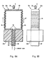
- FIG. 15 shows a fifth preferred embodiment of the slingshot mechanism according to the present invention.
- FIG. 15A shows the device prior to actuation whereas FIG. 15B shows the device after actuation.
- the device of FIG. 15 has a conductive member with a first (322) and a second portion (323) which are arranged essentially parallel within a predefined distance.
- the first portion of the conductive member as shown in FIG. 15A has two legs (322, 322') which have an identical shape.
- the second portion of the conductive member has also two legs (323, 323') of identical shape.
- FIG. 15A shows that first and second conductive member are shaped to have a concave portion (324) forming a pocket in which the payload can be placed.
- the embodiment shown in FIG. 15 is similar to the embodiments shown in FIGS. 5, 3, 4 and 12 in that it employs a support (330) supporting the first portion (322, 322') of the conductive member.
- the support block (330) of FIG. 15A has a very advantageous shape in the region of the first portion of the conductive member. As already shown in FIGS.
- the support block (330) has a concave portion in the region of the center.
- the embodiment of FIG. 15 goes beyond the previous embodiments in that it features also a convex portion below the conductive members in which the concave portion is located.
- the shown convex portion has nearly the shape of a semi circle with a first radius having a cut-out of a semi circle with a second. smaller radius. The improvement achieved by this arrangement can be seen when comparing FIGS. 15A and 15B.
- an electric current is applied to the connection lugs (326, 326') a repulsive force is generated between the first and second portion of the conductive member.
- the side parts of the first and second portion of the conductive member which are parallel to the semi circle of first radius try to enlarge their distance but only a movement of the second portion takes place because the first portion is supported by the support block (330). This type of movement stretches out the concave portion (324) of the second portion of the conductive member.
- the stretching action created by the side parts of the conductive member increases the speed of the payload in direction (340) in addition to the speed which is achieved by repulsive forces in this region alone.
- a very important aspect shown in FIG. 15 but which also could be employed in other embodiments are the anchor means (350, 350'). These anchor means serve to hold the ends of the first and second portion of the conductive member in place when the repulsive forces act.
- the anchor means shown have the form of cylinders which fit into recesses within the support (330). However, the anchor means can also have other shapes as hooks or pins fixing the position of the ends of the conductive member portions with respect to a support.
- anchor means When anchor means are used there is no need for parts of the conductive member to have a particular stiffness to achieve a slingshot action. This means that materials with lower stiffness can be used which also makes it possible to decrease the material thickness thus lowering the weight of the second portion of the conductive member. Any reduction in weight of the second portion of the conductive member is advantageous because acceleration of this portion consumes energy which better can be used to accelerate the payload.
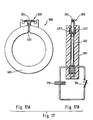
- FIG. 16 shows a pulse transformer for transforming a high voltage high current electrical pulse into a pulse of lower voltage and even higher current.
- the transformer (400) has a primary spool with a certain number of turns. The number of turns is preferably in the range of 2 to 100.
- the secondary spool (402) which is arranged co-axially with the primary spool (401) has only a single turn.
- the secondary spool has preferably the shape of a ring with a slit (403).
- a slingshot module (300) is electrically connected to the secondary spool in a way that the connection lugs of the slingshot module have electrical contact with the two sides of the secondary spool.
- the slingshot module shown in FIG. 16 is the embodiment shown in FIG. 15. However, it is within the scope of the present invention to use other slingshot modules according to the present invention in connection with the pulse transformer.
- the pulse transformer is coupled with the primary spools input lugs (404) to a current supply as for example shown in FIGS. 10 and 11.
- the pulse transformer can be part of an injection device (10) as shown in Fig 10 or can be a disposable part which is sold together with a slingshot module.
- Figure 17 shows a further preferred embodiment based on the pulse transformer of figure 16.
- Figure 17A is a module (500) comprising a secondary spool (402) coupled to a slingshot module (300).
- the module can be made as a single piece unit in which the supply leads of the slingshot module are directly connected to the secondary spool. When such a module (500) has been used it can be easily replaced by a new module.
- Figure 17B shows an embodiment in which the module (500) is disposed in a holder (501) with a slit.
- the primary spool (401) has preferably a first (401) and a second section (401') which are disposed on opposite sides of the secondary spool (402). Reactive forces between first and second spool can be balanced with such an embodiment.
- Embodiments with first and secondary spool belonging to separate pieces have the advantage that electrical contacts between the disposable module (500) and the slingshot module can be eliminated thus avoiding loose contacts.
- a further advantage of such embodiments is that accessible contacts can be avoided due to inductive coupling thus enhancing user safety.
Landscapes
- Health & Medical Sciences (AREA)
- Engineering & Computer Science (AREA)
- Hematology (AREA)
- Life Sciences & Earth Sciences (AREA)
- General Engineering & Computer Science (AREA)
- Electromagnetism (AREA)
- Vascular Medicine (AREA)
- Anesthesiology (AREA)
- Biomedical Technology (AREA)
- Heart & Thoracic Surgery (AREA)
- Physics & Mathematics (AREA)
- Plasma & Fusion (AREA)
- Animal Behavior & Ethology (AREA)
- General Health & Medical Sciences (AREA)
- Public Health (AREA)
- Veterinary Medicine (AREA)
- Infusion, Injection, And Reservoir Apparatuses (AREA)
- Devices For Conveying Motion By Means Of Endless Flexible Members (AREA)
- Magnetically Actuated Valves (AREA)
- Nozzles (AREA)
- Media Introduction/Drainage Providing Device (AREA)
Claims (29)
- Dispositif électromagnétique d'injection transdermique (10) qui injecte une charge utile (28) dans le tissu d'un organisme, comprenant :dans lequel la charge utile est fixée de manière libérable à une partie du mécanisme de génération de force de sorte que la charge utile soit accélérée en même temps que ladite partie du mécanisme de génération de force à une vitesse, 1a vitesse requise pour l'injection de la charge utile dans les tissus, par la force prédéterminée générée et que la charge utile soit séparée de la partie du mécanisme de génération de force après l'accélération de la charge utile, tandis que ladite partie d'accélération dudit mécanisme de génération de force reste fixée audit mécanisme.un mécanisme de génération de force électromagnétique (12) qui génère au moins une force prédéterminée dans une direction prédéterminée par répulsion électromagnétique en réponse à un courant circulant à travers le mécanisme de génération de force ;une alimentation électrique (108) configurée pour délivrer une ou plusieurs impulsions de haute intensité et de courte durée ;un commutateur (106) qui, de manière sélective, connecte électriquement l'alimentation et le mécanisme de génération de force l'un à l'autre ; et
- Dispositif électromagnétique d'injection transdermique selon la revendication 1, dans lequel le mécanisme de génération de force comprend un élément conducteur (20) qui est configuré géométriquement de sorte que l'élément conducteur génère des forces de répulsion électromagnétiques dans une direction prédéterminée en réponse à l'impulsion de haute intensité et de courte durée provenant de l'alimentation, et dans lequel la charge utile est fixée de manière libérable à une partie de l'élément conducteur de sorte que la charge utile soit accélérée à la vitesse requise pour l'injection par les forces de répulsion électromagnétiques générées par l'élément conducteur.
- Dispositif électromagnétique d'injection transdermique selon la revendication 2, dans lequel l'alimentation électrique comprend un condensateur haute tension à faible inductance.
- Dispositif électromagnétique d'injection transdermique selon la revendication 2, dans lequel le commutateur est un commutateur mécanique du type unipolaire unidirectionnel comportant des contacts métalliques.
- Dispositif selon la revendication 1, dans lequel le mécanisme de génération de force électromagnétique comprend un élément conducteur comportant des première et deuxième parties qui sont agencées géométriquement l'une par rapport à l'autre de telle sorte qu'un courant à travers l'élément conducteur circule de façon essentiellement antiparallèle dans lesdites première et deuxième parties, générant de ce fait une force de répulsion entre lesdites parties.
- Dispositif selon la revendication 1, dans lequel le mécanisme de génération de force électromagnétique comprend au moins deux éléments conducteurs opposés et des moyens pour appliquer un courant auxdits au moins deux éléments conducteurs opposés afin de générer une force de répulsion entre lesdits éléments.
- Dispositif selon la revendication 5, dans lequel lesdites première et deuxième parties sont agencées essentiellement parallèlement avec une distance d'environ 0,025 à 0,1 millimètre entre elles.
- Dispositif selon la revendication 5, dans lequel ledit mécanisme de génération de force électromagnétique comprend des première et deuxième sections qui sont de formes essentiellement identiques.
- Dispositif selon la revendication 8, dans lequel chacune desdites première et deuxième sections comprend un élément conducteur comportant des première et deuxième parties qui sont agencées essentiellement parallèlement sur une distance prédéfinie.
- Dispositif selon la revendication 9, dans lequel ladite distance prédéfinie est d'environ 2 à 5 mm.
- Dispositif selon la revendication 9, dans lequel lesdites première et deuxième sections sont connectées l'une à l'autre au moyen de ladite deuxième partie dudit élément conducteur.
- Dispositif selon la revendication 8, dans lequel lesdites première et deuxième sections sont agencées pour former une poche dans laquelle la charge utile est située.
- Dispositif selon la revendication 12, dans lequel la charge utile est fixée de manière libérable à la partie de poche de l'élément conducteur.
- Dispositif selon la revendication 8, dans lequel des première et deuxième sections dudit mécanisme de génération de force électromagnétique forment ensemble un « M ».
- Dispositif selon la revendication 5, dans lequel le dispositif comprend un support (30) supportant ladite première partie dudit élément conducteur tandis que la charge utile est fixée à la deuxième partie.
- Dispositif selon la revendication 9, dans lequel le dispositif comprend un support (30) supportant lesdites premières parties desdites première et deuxième sections.
- Dispositif selon la revendication 16, dans lequel le support (30) comporte une surface supérieure (38) de forme concave.
- Dispositif selon la revendication 5, dans lequel lesdites première et deuxième parties sont connectées par au moins un moyen d'ancrage qui est fixé spatialement.
- Dispositif selon la revendication 18, dans lequel le mécanisme de génération de force électromagnétique comprend des première et deuxième sections qui sont de formes essentiellement identiques et chacune des sections comprend un moyen d'ancrage.
- Dispositif selon la revendication 19, dans lequel chaque section comprend une première partie connectée à un pôle électrique d'une alimentation à une extrémité et qui est fixée à un moyen d'ancrage à l'autre extrémité.
- Dispositif selon la revendication 20, comprenant un support qui supporte ladite première partie.
- Dispositif selon la revendication 20, dans lequel ledit support comporte une partie convexe et une partie concave, ladite partie concave étant située dans la région où les première et deuxième sections se rencontrent.
- Dispositif selon la revendication 22, dans lequel la partie convexe présente essentiellement la forme d'un segment de cercle.
- Dispositif selon la revendication 22, dans lequel les première et deuxième parties desdits moyens de génération de force électromagnétique sont agencées essentiellement parallèlement audit support.
- Dispositif selon la revendication 1, dans lequel l'alimentation électrique comprend un transformateur (400) qui transforme une impulsion électrique haute tension avec un courant donné en une impulsion basse tension avec un courant supérieur audit courant donné.
- Dispositif selon la revendication 25, dans lequel ledit transformateur (400) comprend une bobine primaire (401) et une bobine secondaire (402), ladite bobine secondaire étant connectée à des contacts électriques dudit mécanisme de génération de force électromagnétique.
- Dispositif selon la revendication 26, dans lequel ladite bobine primaire comporte 2 à 100 tours et ladite bobine secondaire comporte un seul tour.
- Dispositif selon la revendication 25, dans lequel ladite bobine secondaire de transformateur (402) forme une unité d'une seule pièce (500) avec le mécanisme de génération de force électromagnétique (300).
- Dispositif selon la revendication 28, comportant une fente de réception pour y recevoir ladite bobine secondaire, et ladite bobine primaire (401) est disposée essentiellement coaxialement à la bobine secondaire lorsque la bobine secondaire est reçue dans ladite fente.
Applications Claiming Priority (3)
| Application Number | Priority Date | Filing Date | Title |
|---|---|---|---|
| US08/897,433 US6074360A (en) | 1997-07-21 | 1997-07-21 | Electromagnetic transdermal injection device and methods related thereto |
| US897433 | 1997-07-21 | ||
| PCT/EP1998/004474 WO1999004838A1 (fr) | 1997-07-21 | 1998-07-18 | Dispositif electromagnetique d'injection transdermique et procedes correspondants |
Publications (2)
| Publication Number | Publication Date |
|---|---|
| EP0998315A1 EP0998315A1 (fr) | 2000-05-10 |
| EP0998315B1 true EP0998315B1 (fr) | 2004-03-03 |
Family
ID=25407898
Family Applications (1)
| Application Number | Title | Priority Date | Filing Date |
|---|---|---|---|
| EP98941360A Expired - Lifetime EP0998315B1 (fr) | 1997-07-21 | 1998-07-18 | Dispositif electromagnetique d'injection transdermique |
Country Status (9)
| Country | Link |
|---|---|
| US (1) | US6074360A (fr) |
| EP (1) | EP0998315B1 (fr) |
| JP (1) | JP2002505123A (fr) |
| AT (1) | ATE260685T1 (fr) |
| DE (1) | DE69822161T2 (fr) |
| DK (1) | DK0998315T3 (fr) |
| ES (1) | ES2214724T3 (fr) |
| PT (1) | PT998315E (fr) |
| WO (1) | WO1999004838A1 (fr) |
Cited By (1)
| Publication number | Priority date | Publication date | Assignee | Title |
|---|---|---|---|---|
| RU2605053C2 (ru) * | 2015-11-06 | 2016-12-20 | Геннадий Леонидович Багич | Низкочастотный излучатель электромагнитной энергии и способ его изготовления |
Families Citing this family (76)
| Publication number | Priority date | Publication date | Assignee | Title |
|---|---|---|---|---|
| GB9426379D0 (en) | 1994-12-23 | 1995-03-01 | Oxford Biosciences Ltd | Particle delivery |
| FR2903769A1 (fr) * | 1995-02-14 | 2008-01-18 | Saint Louis Inst | Dispositif d'accelaration d'un corps de lancement |
| US6036924A (en) | 1997-12-04 | 2000-03-14 | Hewlett-Packard Company | Cassette of lancet cartridges for sampling blood |
| US6391005B1 (en) | 1998-03-30 | 2002-05-21 | Agilent Technologies, Inc. | Apparatus and method for penetration with shaft having a sensor for sensing penetration depth |
| US6406455B1 (en) * | 1998-12-18 | 2002-06-18 | Biovalve Technologies, Inc. | Injection devices |
| GB9905933D0 (en) * | 1999-03-15 | 1999-05-05 | Powderject Res Ltd | Neeedleless syringe |
| FR2796290B1 (fr) * | 1999-07-16 | 2001-09-14 | Cross Site Technologies | Seringue sans aiguille fonctionnant avec un generateur d'onde de choc a travers une paroi |
| DE19946059A1 (de) * | 1999-09-25 | 2001-03-29 | Roche Diagnostics Gmbh | System zur transdermalen Gewinnung von Körperflüssigkeit |
| WO2001051109A1 (fr) * | 2000-01-07 | 2001-07-19 | Biovalve Technologies, Inc. | Dispositif d"injection |
| US6830173B2 (en) | 2000-08-25 | 2004-12-14 | Senco Products, Inc. | Impact device |
| US8641644B2 (en) | 2000-11-21 | 2014-02-04 | Sanofi-Aventis Deutschland Gmbh | Blood testing apparatus having a rotatable cartridge with multiple lancing elements and testing means |
| EP1339442A4 (fr) | 2000-11-30 | 2006-12-27 | Biovalve Technologies Inc | Systemes d'injection |
| US7025774B2 (en) | 2001-06-12 | 2006-04-11 | Pelikan Technologies, Inc. | Tissue penetration device |
| ES2357887T3 (es) | 2001-06-12 | 2011-05-03 | Pelikan Technologies Inc. | Aparato para mejorar la tasa de éxito de obtención de sangre a partir de una punción capilar. |
| US9427532B2 (en) | 2001-06-12 | 2016-08-30 | Sanofi-Aventis Deutschland Gmbh | Tissue penetration device |
| DE60234598D1 (de) | 2001-06-12 | 2010-01-14 | Pelikan Technologies Inc | Selbstoptimierende lanzettenvorrichtung mit adaptationsmittel für zeitliche schwankungen von hauteigenschaften |
| US9226699B2 (en) | 2002-04-19 | 2016-01-05 | Sanofi-Aventis Deutschland Gmbh | Body fluid sampling module with a continuous compression tissue interface surface |
| US7981056B2 (en) | 2002-04-19 | 2011-07-19 | Pelikan Technologies, Inc. | Methods and apparatus for lancet actuation |
| DE60234597D1 (de) | 2001-06-12 | 2010-01-14 | Pelikan Technologies Inc | Gerät und verfahren zur entnahme von blutproben |
| AU2002348683A1 (en) | 2001-06-12 | 2002-12-23 | Pelikan Technologies, Inc. | Method and apparatus for lancet launching device integrated onto a blood-sampling cartridge |
| US8337419B2 (en) | 2002-04-19 | 2012-12-25 | Sanofi-Aventis Deutschland Gmbh | Tissue penetration device |
| AU2002315180A1 (en) | 2001-06-12 | 2002-12-23 | Pelikan Technologies, Inc. | Electric lancet actuator |
| US9795747B2 (en) | 2010-06-02 | 2017-10-24 | Sanofi-Aventis Deutschland Gmbh | Methods and apparatus for lancet actuation |
| DE10151471A1 (de) * | 2001-10-18 | 2003-05-15 | Disetronic Licensing Ag | Injektionsgerät mit Energiespeicher |
| US6939323B2 (en) * | 2001-10-26 | 2005-09-06 | Massachusetts Institute Of Technology | Needleless injector |
| US7892183B2 (en) | 2002-04-19 | 2011-02-22 | Pelikan Technologies, Inc. | Method and apparatus for body fluid sampling and analyte sensing |
| US7648468B2 (en) | 2002-04-19 | 2010-01-19 | Pelikon Technologies, Inc. | Method and apparatus for penetrating tissue |
| US8267870B2 (en) | 2002-04-19 | 2012-09-18 | Sanofi-Aventis Deutschland Gmbh | Method and apparatus for body fluid sampling with hybrid actuation |
| US7491178B2 (en) | 2002-04-19 | 2009-02-17 | Pelikan Technologies, Inc. | Method and apparatus for penetrating tissue |
| US8702624B2 (en) | 2006-09-29 | 2014-04-22 | Sanofi-Aventis Deutschland Gmbh | Analyte measurement device with a single shot actuator |
| US8372016B2 (en) | 2002-04-19 | 2013-02-12 | Sanofi-Aventis Deutschland Gmbh | Method and apparatus for body fluid sampling and analyte sensing |
| US7547287B2 (en) | 2002-04-19 | 2009-06-16 | Pelikan Technologies, Inc. | Method and apparatus for penetrating tissue |
| US7226461B2 (en) | 2002-04-19 | 2007-06-05 | Pelikan Technologies, Inc. | Method and apparatus for a multi-use body fluid sampling device with sterility barrier release |
| US9314194B2 (en) | 2002-04-19 | 2016-04-19 | Sanofi-Aventis Deutschland Gmbh | Tissue penetration device |
| US7175642B2 (en) | 2002-04-19 | 2007-02-13 | Pelikan Technologies, Inc. | Methods and apparatus for lancet actuation |
| US7371247B2 (en) | 2002-04-19 | 2008-05-13 | Pelikan Technologies, Inc | Method and apparatus for penetrating tissue |
| US8221334B2 (en) | 2002-04-19 | 2012-07-17 | Sanofi-Aventis Deutschland Gmbh | Method and apparatus for penetrating tissue |
| US7674232B2 (en) | 2002-04-19 | 2010-03-09 | Pelikan Technologies, Inc. | Method and apparatus for penetrating tissue |
| US7232451B2 (en) | 2002-04-19 | 2007-06-19 | Pelikan Technologies, Inc. | Method and apparatus for penetrating tissue |
| US7291117B2 (en) | 2002-04-19 | 2007-11-06 | Pelikan Technologies, Inc. | Method and apparatus for penetrating tissue |
| US8579831B2 (en) | 2002-04-19 | 2013-11-12 | Sanofi-Aventis Deutschland Gmbh | Method and apparatus for penetrating tissue |
| US9795334B2 (en) | 2002-04-19 | 2017-10-24 | Sanofi-Aventis Deutschland Gmbh | Method and apparatus for penetrating tissue |
| US9248267B2 (en) | 2002-04-19 | 2016-02-02 | Sanofi-Aventis Deustchland Gmbh | Tissue penetration device |
| US7901362B2 (en) | 2002-04-19 | 2011-03-08 | Pelikan Technologies, Inc. | Method and apparatus for penetrating tissue |
| US7297122B2 (en) | 2002-04-19 | 2007-11-20 | Pelikan Technologies, Inc. | Method and apparatus for penetrating tissue |
| US7229458B2 (en) | 2002-04-19 | 2007-06-12 | Pelikan Technologies, Inc. | Method and apparatus for penetrating tissue |
| US8784335B2 (en) | 2002-04-19 | 2014-07-22 | Sanofi-Aventis Deutschland Gmbh | Body fluid sampling device with a capacitive sensor |
| US8360992B2 (en) | 2002-04-19 | 2013-01-29 | Sanofi-Aventis Deutschland Gmbh | Method and apparatus for penetrating tissue |
| US7717863B2 (en) | 2002-04-19 | 2010-05-18 | Pelikan Technologies, Inc. | Method and apparatus for penetrating tissue |
| US7976476B2 (en) | 2002-04-19 | 2011-07-12 | Pelikan Technologies, Inc. | Device and method for variable speed lancet |
| US7909778B2 (en) | 2002-04-19 | 2011-03-22 | Pelikan Technologies, Inc. | Method and apparatus for penetrating tissue |
| US7331931B2 (en) | 2002-04-19 | 2008-02-19 | Pelikan Technologies, Inc. | Method and apparatus for penetrating tissue |
| WO2004021882A2 (fr) * | 2002-09-06 | 2004-03-18 | Massachusetts Institute Of Technology | Mesure de proprietes d'un element anatomique |
| US8574895B2 (en) | 2002-12-30 | 2013-11-05 | Sanofi-Aventis Deutschland Gmbh | Method and apparatus using optical techniques to measure analyte levels |
| DE10306716A1 (de) * | 2003-02-17 | 2004-09-02 | Lell, Peter, Dr.-Ing. | Vorrichtung zum Injizieren eines staub-oder pulverförmigen Stoffs in ein Gewebe eines Körpers |
| EP2238892A3 (fr) | 2003-05-30 | 2011-02-09 | Pelikan Technologies Inc. | Appareil pour prendre de fluide du corps |
| WO2004107964A2 (fr) | 2003-06-06 | 2004-12-16 | Pelikan Technologies, Inc. | Procede et appareil d'echantillonnage de fluides anatomiques et d'examen de l'analysat |
| WO2006001797A1 (fr) | 2004-06-14 | 2006-01-05 | Pelikan Technologies, Inc. | Element penetrant peu douloureux |
| IL157981A (en) | 2003-09-17 | 2014-01-30 | Elcam Medical Agricultural Cooperative Ass Ltd | Auto injector |
| US8282576B2 (en) | 2003-09-29 | 2012-10-09 | Sanofi-Aventis Deutschland Gmbh | Method and apparatus for an improved sample capture device |
| EP1680014A4 (fr) | 2003-10-14 | 2009-01-21 | Pelikan Technologies Inc | Procede et appareil fournissant une interface-utilisateur variable |
| WO2005065414A2 (fr) | 2003-12-31 | 2005-07-21 | Pelikan Technologies, Inc. | Procede et appareil permettant d'ameliorer le flux fluidique et le prelevement d'echantillons |
| US7822454B1 (en) | 2005-01-03 | 2010-10-26 | Pelikan Technologies, Inc. | Fluid sampling device with improved analyte detecting member configuration |
| IL160891A0 (en) | 2004-03-16 | 2004-08-31 | Auto-mix needle | |
| WO2006011062A2 (fr) | 2004-05-20 | 2006-02-02 | Albatros Technologies Gmbh & Co. Kg | Hydrogel imprimable pour biocapteurs |
| EP1765194A4 (fr) | 2004-06-03 | 2010-09-29 | Pelikan Technologies Inc | Procede et appareil pour la fabrication d'un dispositif d'echantillonnage de liquides |
| US9775553B2 (en) | 2004-06-03 | 2017-10-03 | Sanofi-Aventis Deutschland Gmbh | Method and apparatus for a fluid sampling device |
| US8652831B2 (en) | 2004-12-30 | 2014-02-18 | Sanofi-Aventis Deutschland Gmbh | Method and apparatus for analyte measurement test time |
| US7833189B2 (en) | 2005-02-11 | 2010-11-16 | Massachusetts Institute Of Technology | Controlled needle-free transport |
| US8591457B2 (en) * | 2005-08-10 | 2013-11-26 | Alza Corporation | Method for making a needle-free jet injection drug delivery device |
| WO2009126900A1 (fr) | 2008-04-11 | 2009-10-15 | Pelikan Technologies, Inc. | Procédé et appareil pour dispositif de détection d’analyte |
| US9375169B2 (en) | 2009-01-30 | 2016-06-28 | Sanofi-Aventis Deutschland Gmbh | Cam drive for managing disposable penetrating member actions with a single motor and motor and control system |
| WO2011028716A1 (fr) * | 2009-09-01 | 2011-03-10 | Massachusetts Institute Of Technology | Procédé d'identification à système non linéaire pour tester l'efficacité de produits de soins de la peau |
| WO2011028719A2 (fr) | 2009-09-01 | 2011-03-10 | Massachusetts Institute Of Technology | Techniques d'identification de systèmes non linéaires et dispositifs pour découvrir des propriétés de tissu dynamiques et statiques |
| WO2011075545A1 (fr) | 2009-12-15 | 2011-06-23 | Massachusetts Institute Of Technogy | Dispositif de nettoyage actionné par la force de lorentz |
| US8965476B2 (en) | 2010-04-16 | 2015-02-24 | Sanofi-Aventis Deutschland Gmbh | Tissue penetration device |
Family Cites Families (37)
| Publication number | Priority date | Publication date | Assignee | Title |
|---|---|---|---|---|
| US3736933A (en) * | 1970-12-02 | 1973-06-05 | B Szabo | Burstable seamed hypodermic applicators |
| US3788315A (en) * | 1971-04-20 | 1974-01-29 | S Laurens | Disposable cutaneous transjector |
| FR2360031A1 (fr) * | 1976-07-27 | 1978-02-24 | Klein Max | Dispositif distributeur silencieux d'un jet de gaz et application au diagnostic medical |
| US4432333A (en) * | 1977-11-11 | 1984-02-21 | Kurherr Waldemar H | Electromagnetic projectile accelerator |
| IT1105653B (it) * | 1978-06-20 | 1985-11-04 | Craighero Margherita | Apparecchio aerosolizzatore |
| US4656918A (en) * | 1985-02-20 | 1987-04-14 | The United States Of America As Represented By The Secretary Of The Navy | Electromagnetic induction method and apparatus therefor for collapsing and propelling a deformable workpiece |
| US4635587A (en) * | 1985-06-06 | 1987-01-13 | Cowtronics, Inc. | Method and apparatus for detecting standing heat in cattle |
| US4817494A (en) * | 1987-04-06 | 1989-04-04 | The United States Of America As Represented By The United States Department Of Energy | Magnetic reconnection launcher |
| US4760769A (en) * | 1987-04-27 | 1988-08-02 | The United States Of America As Represented By The Secretary Of The Army | High-power, rapid fire railgun |
| GB2206794A (en) * | 1987-07-14 | 1989-01-18 | Richard Kiteley Power | Syringe |
| GB2211589B (en) * | 1987-10-24 | 1990-03-07 | British Aerospace | Electromagnetic launcher. |
| US4858511A (en) * | 1988-03-14 | 1989-08-22 | The United States Of America As Represented By The Secretary Of The Army | Superconductive levitated armatures for electromagnetic launchers |
| US5042359A (en) * | 1988-04-28 | 1991-08-27 | Rheinmetall Gmbh | Projectile accelerating device |
| US4922800A (en) * | 1988-10-07 | 1990-05-08 | Amoco Corporation | Magnetic slingshot accelerator |
| US4926741A (en) * | 1988-12-12 | 1990-05-22 | Polytechnic University | Apparatus for driving a coil launcher |
| US4966884A (en) * | 1989-01-19 | 1990-10-30 | International Superconductor Corp. | DC powered hybrid coil gun employing superconducting elements |
| US4971949A (en) * | 1989-06-21 | 1990-11-20 | General Electric Company | Electromagnetic launcher |
| US5141131A (en) * | 1989-06-30 | 1992-08-25 | Dowelanco | Method and apparatus for the acceleration of a propellable matter |
| US5122506A (en) * | 1989-08-10 | 1992-06-16 | Howard J. Greenwald | Contactless mass moving system |
| US4960760A (en) * | 1989-08-10 | 1990-10-02 | Howard J. Greenwald | Contactless mass transfer system |
| US5168118A (en) * | 1989-11-13 | 1992-12-01 | Schroeder Jon M | Method for electromagnetic acceleration of an object |
| US5269327A (en) * | 1989-12-01 | 1993-12-14 | Philip Morris Incorporated | Electrical smoking article |
| US5204253A (en) * | 1990-05-29 | 1993-04-20 | E. I. Du Pont De Nemours And Company | Method and apparatus for introducing biological substances into living cells |
| US5173568A (en) * | 1990-08-06 | 1992-12-22 | General Dynamics Corporation, Space Systems Division | Integrated superconducting reconnecting magnetic gun |
| WO1992004439A1 (fr) * | 1990-08-30 | 1992-03-19 | Brian John Bellhouse | Appareil balistique |
| US5125321A (en) * | 1990-12-06 | 1992-06-30 | The United States Of America As Represented By The United States Department Of Energy | Apparatus for and method of operating a cylindrical pulsed induction mass launcher |
| US5105713A (en) * | 1991-03-11 | 1992-04-21 | The United States Of America As Represented By The Secretary Of The Army | Electromagnetically accelerated projectile |
| DE4131595C2 (de) * | 1991-09-23 | 1995-02-09 | Rheinmetall Gmbh | Elektromagnetischer Beschleuniger in Flachspulenanordnung |
| ATE195268T1 (de) * | 1992-05-06 | 2000-08-15 | Mallinckrodt Inc | Behälter und verschluss zur aufrechterhaltung der stabilität von natriumhypochloritlösungen |
| TW360548B (en) * | 1993-04-08 | 1999-06-11 | Powderject Res Ltd | Products for therapeutic use |
| GB9405952D0 (en) * | 1994-03-25 | 1994-05-11 | Zeneca Ltd | Aqueous ophthalmic sprays |
| US5435282A (en) * | 1994-05-19 | 1995-07-25 | Habley Medical Technology Corporation | Nebulizer |
| WO1996018425A1 (fr) * | 1994-12-17 | 1996-06-20 | Bailey, William, John | Injecteur |
| BR9610620A (pt) * | 1995-09-28 | 1999-12-21 | Injectiles Ltd | Lançador de projéteis lìquidos. |
| US5694920A (en) * | 1996-01-25 | 1997-12-09 | Abrams; Andrew L. | Inhalation device |
| US6690767B2 (en) * | 1998-10-29 | 2004-02-10 | Direct Radiography Corp. | Prototile motif for anti-scatter grids |
| US7052457B2 (en) * | 2002-07-11 | 2006-05-30 | Fanous Refaat S | Self-retaining retractor |
-
1997
- 1997-07-21 US US08/897,433 patent/US6074360A/en not_active Expired - Fee Related
-
1998
- 1998-07-18 PT PT98941360T patent/PT998315E/pt unknown
- 1998-07-18 JP JP2000503887A patent/JP2002505123A/ja active Pending
- 1998-07-18 DE DE69822161T patent/DE69822161T2/de not_active Expired - Fee Related
- 1998-07-18 DK DK98941360T patent/DK0998315T3/da active
- 1998-07-18 AT AT98941360T patent/ATE260685T1/de not_active IP Right Cessation
- 1998-07-18 ES ES98941360T patent/ES2214724T3/es not_active Expired - Lifetime
- 1998-07-18 EP EP98941360A patent/EP0998315B1/fr not_active Expired - Lifetime
- 1998-07-18 WO PCT/EP1998/004474 patent/WO1999004838A1/fr active IP Right Grant
Cited By (1)
| Publication number | Priority date | Publication date | Assignee | Title |
|---|---|---|---|---|
| RU2605053C2 (ru) * | 2015-11-06 | 2016-12-20 | Геннадий Леонидович Багич | Низкочастотный излучатель электромагнитной энергии и способ его изготовления |
Also Published As
| Publication number | Publication date |
|---|---|
| ATE260685T1 (de) | 2004-03-15 |
| DE69822161D1 (de) | 2004-04-08 |
| EP0998315A1 (fr) | 2000-05-10 |
| ES2214724T3 (es) | 2004-09-16 |
| DK0998315T3 (da) | 2004-07-12 |
| WO1999004838A1 (fr) | 1999-02-04 |
| DE69822161T2 (de) | 2004-12-30 |
| JP2002505123A (ja) | 2002-02-19 |
| PT998315E (pt) | 2004-06-30 |
| US6074360A (en) | 2000-06-13 |
Similar Documents
| Publication | Publication Date | Title |
|---|---|---|
| EP0998315B1 (fr) | Dispositif electromagnetique d'injection transdermique | |
| CN101380494A (zh) | 无针注射器 | |
| KR100820762B1 (ko) | 습식/건식 자동 주사기 조립체 | |
| CA2597666C (fr) | Transport asservi sans aiguille | |
| CN101132821A (zh) | 无针透皮传送装置 | |
| US20070191758A1 (en) | Controlled needle-free transport | |
| HUE025052T2 (en) | A sharpened device for electrically mediated delivery of medical substances | |
| CN111356490B (zh) | 混合和/或重配系统 | |
| LV11833B (en) | Needleless syringe using supersonic gas flow for particle deliwery | |
| WO2019203584A1 (fr) | Système d'administration de médicament par microjet | |
| CN111356491B (zh) | 混合和/或重配系统以及相应方法 | |
| KR20240055701A (ko) | 자기장을 이용한 무침 주사기 | |
| EP0850394B1 (fr) | Dispositif de lancement de projectiles fluides | |
| CN111356492B (zh) | 装置以及混合和/或重配方法 | |
| EP1289581B1 (fr) | Injection de medicament transdermique a assistance electrique | |
| KR102641201B1 (ko) | 무침 주사기 | |
| EP4052744A1 (fr) | Timbre multi-injection | |
| KR20220108337A (ko) | 유도전류형 무바늘 약물 분사장치 |
Legal Events
| Date | Code | Title | Description |
|---|---|---|---|
| PUAI | Public reference made under article 153(3) epc to a published international application that has entered the european phase |
Free format text: ORIGINAL CODE: 0009012 |
|
| 17P | Request for examination filed |
Effective date: 20000219 |
|
| AK | Designated contracting states |
Kind code of ref document: A1 Designated state(s): AT BE CH DE DK ES FI FR GB GR IE IT LI LU NL PT SE |
|
| RIN1 | Information on inventor provided before grant (corrected) |
Inventor name: BEUTTENMUELLER, MANFRED Inventor name: WINTER, GERHARD Inventor name: MATTERN, MARKUS Inventor name: MEACHAM, GEORGE, BEVAN, KIRBY Inventor name: HAAR, HANS-PETER |
|
| 17Q | First examination report despatched |
Effective date: 20020924 |
|
| GRAP | Despatch of communication of intention to grant a patent |
Free format text: ORIGINAL CODE: EPIDOSNIGR1 |
|
| RTI1 | Title (correction) |
Free format text: ELECTROMAGNETIC TRANSDERMAL INJECTION DEVICE |
|
| GRAS | Grant fee paid |
Free format text: ORIGINAL CODE: EPIDOSNIGR3 |
|
| GRAA | (expected) grant |
Free format text: ORIGINAL CODE: 0009210 |
|
| AK | Designated contracting states |
Kind code of ref document: B1 Designated state(s): AT BE CH DE DK ES FI FR GB GR IE IT LI LU NL PT SE |
|
| REG | Reference to a national code |
Ref country code: GB Ref legal event code: FG4D |
|
| RIN1 | Information on inventor provided before grant (corrected) |
Inventor name: BEUTTENMUELLER, MANFRED Inventor name: WINTER, GERHARD Inventor name: MATTERN, MARKUS Inventor name: MEACHAM, GEORGE, BEVAN, KIRBY Inventor name: HAAR, HANS-PETER |
|
| REG | Reference to a national code |
Ref country code: CH Ref legal event code: EP |
|
| REG | Reference to a national code |
Ref country code: IE Ref legal event code: FG4D |
|
| REF | Corresponds to: |
Ref document number: 69822161 Country of ref document: DE Date of ref document: 20040408 Kind code of ref document: P |
|
| REG | Reference to a national code |
Ref country code: CH Ref legal event code: NV Representative=s name: A. BRAUN, BRAUN, HERITIER, ESCHMANN AG PATENTANWAE |
|
| RAP2 | Party data changed (patent owner data changed or rights of a patent transferred) |
Owner name: F. HOFFMANN-LA ROCHE AG Owner name: ROCHE DIAGNOSTICS GMBH |
|
| REG | Reference to a national code |
Ref country code: SE Ref legal event code: TRGR |
|
| REG | Reference to a national code |
Ref country code: PT Ref legal event code: SC4A Free format text: AVAILABILITY OF NATIONAL TRANSLATION Effective date: 20040430 |
|
| NLT2 | Nl: modifications (of names), taken from the european patent patent bulletin |
Owner name: F. HOFFMANN-LA ROCHE AG |
|
| REG | Reference to a national code |
Ref country code: DK Ref legal event code: T3 |
|
| REG | Reference to a national code |
Ref country code: GR Ref legal event code: EP Ref document number: 20040401827 Country of ref document: GR |
|
| REG | Reference to a national code |
Ref country code: ES Ref legal event code: FG2A Ref document number: 2214724 Country of ref document: ES Kind code of ref document: T3 |
|
| ET | Fr: translation filed | ||
| PLBE | No opposition filed within time limit |
Free format text: ORIGINAL CODE: 0009261 |
|
| STAA | Information on the status of an ep patent application or granted ep patent |
Free format text: STATUS: NO OPPOSITION FILED WITHIN TIME LIMIT |
|
| 26N | No opposition filed |
Effective date: 20041206 |
|
| PGFP | Annual fee paid to national office [announced via postgrant information from national office to epo] |
Ref country code: GB Payment date: 20050614 Year of fee payment: 8 Ref country code: AT Payment date: 20050614 Year of fee payment: 8 |
|
| PGFP | Annual fee paid to national office [announced via postgrant information from national office to epo] |
Ref country code: DK Payment date: 20050615 Year of fee payment: 8 |
|
| PGFP | Annual fee paid to national office [announced via postgrant information from national office to epo] |
Ref country code: NL Payment date: 20050616 Year of fee payment: 8 |
|
| PGFP | Annual fee paid to national office [announced via postgrant information from national office to epo] |
Ref country code: PT Payment date: 20050623 Year of fee payment: 8 |
|
| PGFP | Annual fee paid to national office [announced via postgrant information from national office to epo] |
Ref country code: IE Payment date: 20050630 Year of fee payment: 8 |
|
| PGFP | Annual fee paid to national office [announced via postgrant information from national office to epo] |
Ref country code: LU Payment date: 20050701 Year of fee payment: 8 |
|
| PGFP | Annual fee paid to national office [announced via postgrant information from national office to epo] |
Ref country code: SE Payment date: 20050704 Year of fee payment: 8 |
|
| PGFP | Annual fee paid to national office [announced via postgrant information from national office to epo] |
Ref country code: FR Payment date: 20050706 Year of fee payment: 8 |
|
| PGFP | Annual fee paid to national office [announced via postgrant information from national office to epo] |
Ref country code: ES Payment date: 20050715 Year of fee payment: 8 |
|
| PGFP | Annual fee paid to national office [announced via postgrant information from national office to epo] |
Ref country code: GR Payment date: 20050726 Year of fee payment: 8 |
|
| PGFP | Annual fee paid to national office [announced via postgrant information from national office to epo] |
Ref country code: FI Payment date: 20050727 Year of fee payment: 8 |
|
| PGFP | Annual fee paid to national office [announced via postgrant information from national office to epo] |
Ref country code: BE Payment date: 20050728 Year of fee payment: 8 |
|
| PGFP | Annual fee paid to national office [announced via postgrant information from national office to epo] |
Ref country code: DE Payment date: 20050729 Year of fee payment: 8 |
|
| PGFP | Annual fee paid to national office [announced via postgrant information from national office to epo] |
Ref country code: CH Payment date: 20050927 Year of fee payment: 8 |
|
| PG25 | Lapsed in a contracting state [announced via postgrant information from national office to epo] |
Ref country code: IE Free format text: LAPSE BECAUSE OF NON-PAYMENT OF DUE FEES Effective date: 20060718 Ref country code: GB Free format text: LAPSE BECAUSE OF NON-PAYMENT OF DUE FEES Effective date: 20060718 Ref country code: FI Free format text: LAPSE BECAUSE OF NON-PAYMENT OF DUE FEES Effective date: 20060718 Ref country code: AT Free format text: LAPSE BECAUSE OF NON-PAYMENT OF DUE FEES Effective date: 20060718 |
|
| PG25 | Lapsed in a contracting state [announced via postgrant information from national office to epo] |
Ref country code: SE Free format text: LAPSE BECAUSE OF NON-PAYMENT OF DUE FEES Effective date: 20060719 |
|
| PG25 | Lapsed in a contracting state [announced via postgrant information from national office to epo] |
Ref country code: LI Free format text: LAPSE BECAUSE OF NON-PAYMENT OF DUE FEES Effective date: 20060731 Ref country code: DK Free format text: LAPSE BECAUSE OF NON-PAYMENT OF DUE FEES Effective date: 20060731 Ref country code: CH Free format text: LAPSE BECAUSE OF NON-PAYMENT OF DUE FEES Effective date: 20060731 Ref country code: BE Free format text: LAPSE BECAUSE OF NON-PAYMENT OF DUE FEES Effective date: 20060731 |
|
| PGFP | Annual fee paid to national office [announced via postgrant information from national office to epo] |
Ref country code: IT Payment date: 20060731 Year of fee payment: 9 |
|
| PG25 | Lapsed in a contracting state [announced via postgrant information from national office to epo] |
Ref country code: PT Free format text: LAPSE BECAUSE OF NON-PAYMENT OF DUE FEES Effective date: 20070118 |
|
| PG25 | Lapsed in a contracting state [announced via postgrant information from national office to epo] |
Ref country code: NL Free format text: LAPSE BECAUSE OF NON-PAYMENT OF DUE FEES Effective date: 20070201 Ref country code: DE Free format text: LAPSE BECAUSE OF NON-PAYMENT OF DUE FEES Effective date: 20070201 |
|
| REG | Reference to a national code |
Ref country code: PT Ref legal event code: MM4A Free format text: LAPSE DUE TO NON-PAYMENT OF FEES Effective date: 20070118 |
|
| REG | Reference to a national code |
Ref country code: DK Ref legal event code: EBP |
|
| REG | Reference to a national code |
Ref country code: CH Ref legal event code: PL |
|
| EUG | Se: european patent has lapsed | ||
| GBPC | Gb: european patent ceased through non-payment of renewal fee |
Effective date: 20060718 |
|
| NLV4 | Nl: lapsed or anulled due to non-payment of the annual fee |
Effective date: 20070201 |
|
| REG | Reference to a national code |
Ref country code: IE Ref legal event code: MM4A |
|
| REG | Reference to a national code |
Ref country code: FR Ref legal event code: ST Effective date: 20070330 |
|
| REG | Reference to a national code |
Ref country code: ES Ref legal event code: FD2A Effective date: 20060719 |
|
| BERE | Be: lapsed |
Owner name: F. *HOFFMANN-LA ROCHE A.G. Effective date: 20060731 |
|
| PG25 | Lapsed in a contracting state [announced via postgrant information from national office to epo] |
Ref country code: ES Free format text: LAPSE BECAUSE OF NON-PAYMENT OF DUE FEES Effective date: 20060719 |
|
| PG25 | Lapsed in a contracting state [announced via postgrant information from national office to epo] |
Ref country code: FR Free format text: LAPSE BECAUSE OF NON-PAYMENT OF DUE FEES Effective date: 20060731 |
|
| PG25 | Lapsed in a contracting state [announced via postgrant information from national office to epo] |
Ref country code: LU Free format text: LAPSE BECAUSE OF NON-PAYMENT OF DUE FEES Effective date: 20060718 |
|
| PG25 | Lapsed in a contracting state [announced via postgrant information from national office to epo] |
Ref country code: GR Free format text: LAPSE BECAUSE OF NON-PAYMENT OF DUE FEES Effective date: 20070202 |
|
| PG25 | Lapsed in a contracting state [announced via postgrant information from national office to epo] |
Ref country code: IT Free format text: LAPSE BECAUSE OF NON-PAYMENT OF DUE FEES Effective date: 20070718 |