EP0998009A1 - Electromagnetic converter and electronic device with the same - Google Patents
Electromagnetic converter and electronic device with the same Download PDFInfo
- Publication number
- EP0998009A1 EP0998009A1 EP99901168A EP99901168A EP0998009A1 EP 0998009 A1 EP0998009 A1 EP 0998009A1 EP 99901168 A EP99901168 A EP 99901168A EP 99901168 A EP99901168 A EP 99901168A EP 0998009 A1 EP0998009 A1 EP 0998009A1
- Authority
- EP
- European Patent Office
- Prior art keywords
- amorphous metal
- yoke
- magnetic material
- generator
- metal magnetic
- Prior art date
- Legal status (The legal status is an assumption and is not a legal conclusion. Google has not performed a legal analysis and makes no representation as to the accuracy of the status listed.)
- Granted
Links
Images





Classifications
-
- H—ELECTRICITY
- H02—GENERATION; CONVERSION OR DISTRIBUTION OF ELECTRIC POWER
- H02K—DYNAMO-ELECTRIC MACHINES
- H02K1/00—Details of the magnetic circuit
- H02K1/02—Details of the magnetic circuit characterised by the magnetic material
-
- G—PHYSICS
- G04—HOROLOGY
- G04C—ELECTROMECHANICAL CLOCKS OR WATCHES
- G04C10/00—Arrangements of electric power supplies in time-pieces
Definitions
- the present invention relates to an electromagnetic converter such as a small generator, a motor and so on and to electronic equipment provided therewith, and the present invention is particularly applicable to a wrist watch and the like.
- electronically-controlled mechanical timepieces (hereinafter, referred to as electronically-controlled mechanical watches) which convert mechanical energy, which is generated by releasing a mainspring, into electric energy through an electromagnetic converter, control the value of a current flowing in the coil of the electromagnetic converter by actuating a rotation control means by the electric energy and display a time by driving hands fixed to a train wheel (Japanese Examined Patent Publication No. 7-119812 and Japanese Unexamined Patent Publication No. 8-50186, etc.).
- Japanese Unexamined Patent Publication No. 8-5758 proposes, in order to improve the efficiency for converting mechanical energy into electric energy, an arrangement using PC permalloy (hereinafter, referred to as PC material) having coercive force smaller than that of PB permalloy (hereinafter, referred to as PB material) so as to reduce the hysteresis loss of a stator and a coil core which constitute the magnetic circuit of a generator in the electronically-controlled mechanical watches.
- PC material PC permalloy
- PB material PB permalloy
- the electronic timepiece is arranged such that the generator is assembled to a wrist watch main body, electric energy necessary to drive the wrist watch is generated by the movement of an arm and accumulated in a capacitor and an electronic circuit is driven by the electric energy.
- the power of a rotary movement weight is transmitted to the generator through a power transmission mechanism composed of a speed increasing train wheel and electric power is generated by causing an electromagnetic inducing action to a coil by the change of a magnetic field which is generated by the rotation of the rotor.
- These generators comprise a rotor including a permanent magnet, a first yoke disposed around the rotor and a second rotor connected to the first yoke and including a coil.
- the second yoke is placed on the first yoke and the magnetic induction from the upper yoke to the lower yoke is secured through screws as shown in the drawings in Japanese Examined Patent Publication No. 7-38029.
- the PC material, PB material and the like are ordinarily used as the material of the yokes of the magnetic converter.
- the first yoke sinator
- copper loss electrical resistance
- the PC material is used as the first yoke because it can increase a sectional area and accordingly it has magnetic flux density as small as 0.7T and its iron loss is also small.
- the second yoke coil core
- the PB material is used in the second yoke because it has relatively high saturation magnetic flux density of 1.4T although it has iron loss larger than that of the PC material.
- the use of the PB material which has large iron loss but can secure necessary magnetic flux even if the sectional area thereof is reduced, can decrease total loss as compared with the use of the PC material, which must increase the sectional area by which the copper loss of the winding thereof is increased, although its iron loss is low. Accordingly, the PB material is used in the second yoke.
- a material having small iron loss is required for the first yoke (stator) around which no coil is wounded.
- a material having small iron loss and high saturation magnetic flux density is required for the second yoke (coil core) around which the coil is wound.
- the magnetic flux flowing in the magnetic circuit of the electronically-controlled mechanical watches is smaller by one order of magnitude as compared with that of the electronic timepieces provided with the generator devices and further the electronically-controlled mechanical watches have coil windings.
- the sectional area of the yoke of the electronic timepieces is reduced to decrease iron loss, the magnetization flux density is not saturated. Therefore, the PC material having the saturation magnetic flux density as small as 0.7T is used in the electronic timepieces.
- the present invention is an electromagnetic converter comprising a rotor arranged by including a permanent magnet yoke disposed in the vicinity of the rotor for flowing magnetic flux and a coil disposed in the vicinity of the yoke, and the electromagnetic converter is characterized in that at least a portion of the yoke is composed of an amorphous metal magnetic material.
- the present invention is electronic equipment provided with the electromagnetic converter.
- the electronic equipment is preferably arranged as portable type electronic equipment and most preferably arranged as, for example, a portable timepiece.
- the electromagnetic converter may include a small generator, a motor and the like.
- the improvement of efficiency of a generator which is achieved by the reduction of iron loss can increase a duration time in the electronically-controlled mechanical watches and can reduce the size of a rotary movement weight in the electronic timepieces provided with generator devices, whereby the size and thickness of the timepieces can be reduced.
- the yoke is ordinarily composed of magnetic members comprising at least two magnetic materials, and it is preferable that at least one of the magnetic members be composed of the amorphous metal magnetic material.
- an anti-magnetic field is produced in the direction of the flow and acts to prevent the flow of the magnetic flux.
- a magnetization direction (direction in which magnetic flux flows) is the thickness direction of the magnetic materials.
- the amorphous metal magnetic material when a thickness of a sheet is set to, for example, 25 ⁇ m, since the sheet is thinner than the thickness 0.5 mm of a conventional material, for example, a PC material, the amorphous metal magnetic material is greatly affected by the anti-magnetic field and the magnetic flux is difficult to flow therein with a result that the characteristics of the amorphous metal magnetic material are inferior to those of the PC material.
- a joint member to at least one of the two magnetic members, which are in contact with each other and located on an upper side and a lower side, permits the magnetic flux to flow more easily.
- joint member need not be as thick as the magnetic members and it is sufficient for the thickness thereof to be half the thickness of the magnetic members. While it is preferable that the material of the joint member be a PC material which is difficult to be affected by the anti-magnetic field and the raw material thereof is available in a large thickness, it may be composed of an amorphous material (in particular, a Co type).
- a specific example of the amorphous metal magnetic material is a Co amorphous metal.
- the Co amorphous metal magnetic material contains Co in an amount of at least 50 wt%. It may contain Fe, Ni, B, Si and the like as other elements.
- a specific example of the amorphous metal magnetic material may be a Fe amorphous metal.
- the Fe amorphous metal contains Fe in an amount of at least 50 wt%. It may contain B, Si and the like as other elements.
- a specific example of the electronic equipment of the present invention is, for example, an electronically-controlled timepiece to which a small generator is assembled.
- the electronically-controlled timepiece includes (1) an electronic timepiece provided with a generator device for generating power using a rotary movement weight, (2) an electronically-controlled mechanical watch, (3) a quartz watch driven by a step motor, and so forth.
- the electronic timepiece is arranged by comprising at least a generator as the electromagnetic converter of the present invention, a storage means for storing the electromotive force of the generator, a timepiece circuit driven by the storage-means, and a timepiece display unit driven by the timepiece circuit.
- the generator of the electronic timepiece shown in the item (1) specifically comprises a rotary movement weight and a power transmission mechanism for transmitting the power of the rotary movement weight to the small generator.
- the rotary movement weight generates mechanical energy.
- the power transmission mechanism comprises a speed increasing train wheel having a plurality of combined gears.
- the Co amorphous metal magnetic material is used for a first yoke (stator) in the generator of the electronic timepiece provided with the generator device, and the Fe amorphous metal magnetic material is used for a second yoke.
- the Co amorphous metal magnetic material in the first yoke (stator) because it can increase the cross sectional area of the first yoke, has low iron loss and low saturation magnetic flux density (0.7T).
- the second yoke coil core
- the length of a coil wire is increased, thereby increasing copper loss.
- reducing the cross sectional area by the use of the Fe amorphous metal magnetic material, which has high saturation magnetic flux density (1.4T) while the iron loss thereof is larger than that of the Co amorphous metal magnetic material can reduce total loss rather than increasing copper loss by winding a coil around the Co amorphous metal magnetic material having a large cross sectional area. Therefore, it is preferable to use the Fe amorphous metal magnetic material.
- the electronically-controlled mechanical watch shown in the item (2) is arranged by comprising, a main spring, a generator for converting the mechanical energy of the mainspring which is transmitted through a train wheel into electric energy, a time display hands coupled to the train wheel, a reference signal source such as a crystal oscillator or the like which is driven by the converted electric energy and a rotation control means driven by the converted electric energy similarly for controlling the rotation cycle of the generator.
- the yokes of the electronically-controlled mechanical watch are composed of the Co amorphous metal magnetic material.
- the composition of the Co amorphous metal magnetic material is, for example, 66Co-4Fe-1Ni-14B-15Si.
- composition of the Fe amorphous metal magnetic material is, for example, 78Fe-13B-9Si.
- the magnetic torque (rotation load torque) of a rotor and the iron loss of a yoke
- a decrease in iron loss reduces magnetic torque.
- the magnetic torque can be reduced by the use of an amorphous metal magnetic material having small iron loss.
- the rotation load torque necessary to drive the rotor of the generator can be reduced and the period of time during which the mainspring of the electronically-controlled mechanical watch is used (duration time) can be increased.
- the reduction of the rotation load torque for driving the rotor of the generator also permits the reduction in size of, for example, the rotary movement weight and the generator in the electronic timepiece provided with the generator.
- a generated voltage necessary to drive the IC of the electronically-controlled mechanical watch is at least 1 V.
- the torque required by a movement barrel, which constitutes one gear of the train wheel by the gear in which the mainspring is accommodated is at least 30 gcm when the yokes are composed of the PC material and at least 20 gcm when the yokes are composed of the Co amorphous material.
- the voltage of a capacitor in which the electromotive force of the generator is stored (the IC is driven by the output from the capacitor) is made to at least 1 V.
- a period of time from a time when a mainspring is fully wound to a time when it is rewound, that is, a duration time can be determined by (speed increasing ratio ⁇ number of turns of mainspring) ⁇ (rotor frequency ⁇ 60 ⁇ 60 hours) .
- ⁇ speed increasing ratio
- rotor frequency ⁇ 60 ⁇ 60 hours rotation frequency
- the yokes of the generator is composed of an amorphous material
- the yokes are used by increasing the speed increasing ratio to 1.5 times the above speed increasing ratio, that is, to 243,000 in correspondence to the reduction of the power generation torque to 1/1.5 (since the rotational speed of the rotor is constant, the rotational speed of the movement barrel is reduced to 1/1.5)
- the duration time of 1.5 times the above duration time that is, 36 hours can be achieved in the same effective number of turns (5.3 turns).
- the rotary movement weight by which driving power is generated from the generator can be easily moved because the aforesaid magnetic torque is reduced.
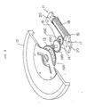
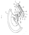
- the small generator of the embodiment is assembled to a wrist watch (an electronic timepiece provided with a generator device) as portable electronic equipment including a self-power-generating-system.
- the wrist watch comprises a small generator 11, a rotary movement weight 12, a power transmission mechanism 13 for transmitting the power of the rotary movement weight 12 to the small generator 11, a storage means (not shown) connected to both the ends of the wire 18 of the small generator 11 for storing the electromotive force of the small generator 11, a watch circuit driven by the storage means, a stepping motor driven by the watch circuit, a gear train wheel driven by the stepping motor, hands attached to the shafts of gears in the gear train wheel, and the like.
- the small generator 11 comprises a rotor 14 arranged by including a permanent magnet, a first yoke 15 disposed around the rotor 14, and a second yoke 17 connected to the first yoke 15.
- the second yoke 17 includes a coil 16 around which the wire 18 is wound.
- the rotary movement weight 12 has a semi-circular shape and its center of gravity is dislocated from the center of rotation thereof.
- the power transmission mechanism 13 comprises a plurality of gears 19A - 19D each having a different number of teeth, and the rotation of the rotary movement weight 12 is transmitted to the rotor 14 of the small generator 11 therethrough at a desired speed increasing ratio, for example, at a speed increasing ratio increased to 100 times the rotational speed of the rotary weight 12.
- the junction 20 of the first yoke 15 to the second yoke 17 is formed by joining the sides of both the yokes 15 and 17. At least one of both the yokes 15 and 17 is composed of a Co amorphous metal magnetic material or a Fe amorphous metal magnetic material.
- joint members 41 be attached under the first and second yokes 15 and 17 and both the yokes 15 and 17 are coupled to each other through the joint members 41.
- the joint members 41 are preferably composed of the Co amorphous metal magnetic material, the Fe amorphous metal magnetic material or a PC material.
- the small generator of the embodiment is assembled to an electronically-controlled mechanical watch as the portable equipment.
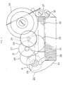
- the electronically-controlled mechanical watch according to the embodiment is arranged by including a train wheel 21, a generator 22 and the like.
- the train wheel 21 includes a movement barrel 23 in which a mainspring is accommodated, a center wheel 24, a third wheel 25, a second wheel 26, a fifth wheel 27 and a sixth wheel 28.
- the generator 22 includes a rotor 31 having a magnet 29, a first yoke 33 having a winding 32 of 40,000 turns and a second yoke 34 composed of a coil 36 having a winding 35 of 110,000 turns.
- the rotation of the movement barrel 23 is sequentially increased through the center wheel 24, the third wheel 25, the second wheel 26, the fifth wheel 27 and the sixth wheel 28 and transmitted to the rotor 31 by being finally increased to 243,000 times the original rotation thereof.
- the junction 37 of the first yoke 33 to the second yoke 34 is formed by joining the sides of both the yokes 33 and 34. At least one of both the yokes 33 and 34 is composed of the Co amorphous metal magnetic material or the Fe amorphous metal magnetic material.
- first and second yokes 33 and 34 are formed symmetrical with respect to the right and left sides thereof as shown in Fig. 5, different from the yokes 33 and 34 shown in Fig. 4.
- openings 33A and 33B in which the magnet 29 of the rotor 31 is accommodated, are positioned with respect to a positioning member 44 composed of a non-magnetic material such as brass and attached to a main plate 49.
- the openings 33A and 33B are pressed against the positioning member 44, whereby the yokes 33 and 34 are positioned.
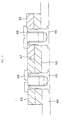
- both the yokes 33 and 34 are positioned through the guide holes thereof fitted on guide pins 45 and both the yokes 33 and 34 are secured to the main plate 49 by screws 48 screwed into the guide pins 45. Since the junction 47 of the sides of both the yokes 33 and 34 has a large magnetic resistance, it is preferable that the eccentric pins 43 inserted into the main plate 49 be disposed to the side surface portions of both the yokes 33 and 34 and both the yokes 33 and 34 be pressed against each other by the eccentric pins 43 so as to reduce magnetic leakage (loss). As shown in Figs. 6 and 7, a joint member 46 composed of the PC member or the like is also attached under the yokes 33 and 34 or placed on the main plate 49 and both the yokes 33 and 34 are coupled to each other through the joint member 46.
- the guide pins 45 and the screws 48 located on the joint sides for originally guiding the yokes be also composed of a magnetic material such as amorphous or the like to secure magnetic flux passing through the yokes.
- the present invention is not limited to a two-pole generator composed of a pair of a N-pole and a S-pole as shown in Figs. 2 to 7 and is similarly applicable to a generator having four or more poles.
- a highly effective generator with small iron loss can be provided by composing the yokes of the multi-pole generator disposed in Japanese Examined Patent Publication No. 7-69440 of the amorphous metal magnetic material according to the present invention.
- the miniaturization of the generator can be realized because much magnetic flux can be gathered, the thickness of a magnet can be reduced and the number of turns of a winding can be decreased.
- Portable equipment of the example relates to the structure of Fig. 2 in the first embodiment.
- a wrist watch was arranged by composing the first yoke 15 of an amorphous metal comprising 66Co-4Fe-1Ni-14B-15Si and the second yoke 17 of an amorphous metal comprising 78Fe-13B-9Si.
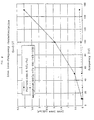
- Fig. 8 shows the result of measurement of iron loss - frequency characteristics of the Co amorphous metal of the example. Further, Fig. 8 also shows the result of similar measurement executed to a conventional PC material (76Ni-4Mo-5.5Cu-Fe).
- Fig. 9 shows the result of measurement of iron loss - frequency characteristics of the Fe amorphous metal of the example. Further, Fig. 9 also shows the result of similar measurement executed to a conventional PB material (46Ni-Fe).
- the size of the rotary movement weight can be reduced by the increase of the efficiency of the generator, whereby the watch can be reduced in thickness and size.
- the tensile stress of the Co amorphous metal of the example is about 100 Kg/mm 2
- the tensile stress of the PC material is about 50 Kg/mm 2 .
- the strength of the material of the Co amorphous metal of the example is twice that of the PC material, there is no possibility of deformation of the material and the material can be easily handled.
- Portable equipment of the example relates to the structure of Figs. 4 to 7 in the second embodiment.
- the shapes and the structures of the yokes 33 and 34 relate to the structure shown in Fig. 5.
- the wrist watch was arranged by composing the first yoke 33 and the second yoke 34 of the amorphous metal comprising 66Co-4Fe-1Ni-14B-15Si.
- the PC material was used as the material of the joint member 46.
- the second yoke 34 (otherwise, the first yoke 33) may be composed of amorphous thin sheets 41 each having a different width and laminated along an ellipse shape.
- the thickness of each thin sheet 41 is set to, for example, 20 - 25 ⁇ m.
- An adhesive layer is composed of a polyester adhesive material or the like and set to a thickness of about 2 ⁇ m.
- the second yoke 34 having the laminated-layer structure can be made by laminating the thin sheets 41 to each other by applying the adhesive material to the thin sheets 41 by transcription, curing the laminated member by leaving it at 200°C for about 40 minutes and thereafter leaving it at 60°C for about 1 week to 10 days.
- the magnetic flux passing through the respective yokes was 0.182 ⁇ Wb and a power generating efficiency was 14.5%.
- the yoke can be used as the electromagnetic converter or the electronic equipment provided with it.
- the electromagnetic converter is also applicable to a motor such as a stepping motor and the like, in addition to the generator shown in the respective embodiments.
- the structure in this case is approximately the same as the structures shown in the figures according to the respective embodiments.
- the material and the characteristics of the motor are substantially the same as those shown in the respective embodiments and the respective examples.
- the electronic equipment provided with the electromagnetic converter of the present invention are, for example, a wrist watch, a wall clock, a clock, a portable personal computer, a pager, a portable phone, and the like.
Landscapes
- Engineering & Computer Science (AREA)
- Power Engineering (AREA)
- Physics & Mathematics (AREA)
- General Physics & Mathematics (AREA)
- Electromechanical Clocks (AREA)
- Iron Core Of Rotating Electric Machines (AREA)
- Electric Clocks (AREA)
Abstract
Description
| Amorphous | PC material | |
| Input energy | 0.76 µW | 1.16 µW |
| (power generation torque) | 20.1 gcm | 30.6 gcm |
| Output energy | 0.117 µW | 1.106 µW |
| (capacitor voltage) | 1.08 V | 1.03 V |
| Power generation efficiency | 15.4% | 9.1% |
Claims (16)
- An electromagnetic converter comprising a rotor arranged by including a permanent magnet, a yoke disposed in the vicinity of the rotor for flowing magnetic flux and a coil disposed in the vicinity of the yoke, wherein at least a portion of the yoke is composed of an amorphous metal magnetic material.
- An electromagnetic converter according to claim 1, wherein the yoke has at least two magnetic members which are formed so as to be substantially in contact with each other partially or entirely through the sides thereof and at least one of the magnetic materials is composed of the amorphous metal magnetic material.
- An electromagnetic converter according to claim 2, wherein a joint member for promoting the flow of magnetic flux between the two magnetic members, which are in contact with each other, is disposed on at least one of the upper side and the lower side of the respective magnetic members.
- An electromagnetic converter according to any of claims 1 - 3, wherein a Co amorphous metal magnetic material is used for a stator as a first yoke around which no coil is wound.
- An electromagnetic converter according to any of claims 1 - 3, wherein a Fe amorphous metal magnetic material is used for a coil core as a second yoke around which a coil is wound.
- An electromagnetic converter according to any of claims 1 - 3, wherein a Co amorphous metal magnetic material is used for a yoke around which a coil is wound.
- An electromagnetic converter according to claim 4 or 6, wherein the Co amorphous metal magnetic material is 66Co-4Fe-1Ni-14B-15Si.
- An electromagnetic converter according to claim 5, wherein the Fe amorphous metal magnetic material is 78Fe-13B-9Si.
- An electromagnetic converter, wherein an electromagnetic converter according to any of claims 1 - 8 is a generator.
- Electronic equipment provided with an electromagnetic converter according to any of claims 1 - 9.
- Electronic equipment, wherein the electronic equipment according to claim 10 is portable electronic equipment.
- Electronic equipment according to claim 10 or 11, wherein the electronic equipment is an electronic timepiece.
- Electronic equipment according to claim 12, wherein the electronic timepiece is an electronic timepiece provided with a generator device which comprises the generator, a storage means of the electromotive force of the generator, a timepiece circuit driven by the storage means, and a timepiece display unit driven by the timepiece circuit.
- Electronic equipment according to claim 13, wherein the Co amorphous metal magnetic material is used for the stator as the first yoke around which no coil is wound and the Fe amorphous metal magnetic material is used for the coil core as the second yoke around which the coil is wound.
- Electronic equipment according to claim 12, wherein the electronic timepiece comprises a mainspring, the generator for converting the mechanical energy of the mainspring transmitted through a train wheel into electric energy, time displaying hands coupled to the train wheel, a reference signal source driven by the converted electric energy and a rotation control means driven by the converted electric energy for controlling the rotation cycle of the generator.
- Electronic equipment according to claim 15, wherein the Co amorphous metal magnetic material is used for the yoke around which the coil is wound.
Applications Claiming Priority (3)
| Application Number | Priority Date | Filing Date | Title |
|---|---|---|---|
| JP1083598 | 1998-01-22 | ||
| JP1083598 | 1998-01-22 | ||
| PCT/JP1999/000288 WO1999038241A1 (en) | 1998-01-22 | 1999-01-22 | Electromagnetic converter and electronic device with the same |
Publications (3)
| Publication Number | Publication Date |
|---|---|
| EP0998009A1 true EP0998009A1 (en) | 2000-05-03 |
| EP0998009A4 EP0998009A4 (en) | 2001-05-23 |
| EP0998009B1 EP0998009B1 (en) | 2008-09-24 |
Family
ID=11761421
Family Applications (1)
| Application Number | Title | Priority Date | Filing Date |
|---|---|---|---|
| EP99901168A Expired - Lifetime EP0998009B1 (en) | 1998-01-22 | 1999-01-22 | Electronic timepiece with a generator |
Country Status (6)
| Country | Link |
|---|---|
| US (1) | US6603236B2 (en) |
| EP (1) | EP0998009B1 (en) |
| JP (1) | JP3551433B2 (en) |
| CN (1) | CN1258853C (en) |
| DE (1) | DE69939617D1 (en) |
| WO (1) | WO1999038241A1 (en) |
Cited By (3)
| Publication number | Priority date | Publication date | Assignee | Title |
|---|---|---|---|---|
| EP1239567A2 (en) | 2001-03-09 | 2002-09-11 | Siemens Aktiengesellschaft | Mobile communication device |
| EP1261100A4 (en) * | 2000-11-17 | 2005-08-24 | Seiko Epson Corp | ELECTROGENIC BLOCK, ELECTRONIC APPARATUS THEREOF, AND METHOD FOR FASTENING THE THICKNESS OF A MAGNETIC CIRCUIT IN AN ELECTRONICALLY CONTROLLED TIME COUNTER AND IN AN ELECTROGENIC BLOCK |
| EP4092492A1 (en) | 2021-05-21 | 2022-11-23 | ETA SA Manufacture Horlogère Suisse | Timepiece movement comprising a generator |
Families Citing this family (17)
| Publication number | Priority date | Publication date | Assignee | Title |
|---|---|---|---|---|
| US6863435B2 (en) * | 1997-08-11 | 2005-03-08 | Seiko Epson Corporation | Spring, mainspring, hairspring, and driving mechanism and timepiece based thereon |
| CN1196042C (en) * | 1997-08-28 | 2005-04-06 | 精工爱普生株式会社 | Spring, power spring, hair spring, driving mechanism utilizing them, and timepiece |
| ES2815926T3 (en) * | 2002-01-30 | 2021-03-31 | Ramon A Caamano | High frequency motor or generator |
| US20040233794A1 (en) * | 2003-02-21 | 2004-11-25 | Seiko Epson Corporation | Timepiece driving apparatus and time calculating apparatus |
| US7551957B2 (en) * | 2003-03-06 | 2009-06-23 | Bioelectronics Corp. | Electromagnetic therapy device and methods |
| FR2920628B1 (en) * | 2007-08-30 | 2011-07-01 | Celsius X Vi Ii | PORTABLE PHONE WITH A MECHANICAL WATCH |
| JP4906647B2 (en) * | 2007-09-07 | 2012-03-28 | セイコープレシジョン株式会社 | Blade drive device |
| JP4906645B2 (en) * | 2007-09-07 | 2012-03-28 | セイコープレシジョン株式会社 | Blade drive device |
| JP4906646B2 (en) * | 2007-09-07 | 2012-03-28 | セイコープレシジョン株式会社 | Blade drive device |
| CH698962B1 (en) * | 2008-06-10 | 2014-10-31 | Rolex Sa | Barrel spring and method for its shaping. |
| TWI394352B (en) | 2009-07-16 | 2013-04-21 | Silicon Touch Tech Inc | Power generating device |
| CN101997385B (en) * | 2009-08-17 | 2013-07-31 | 点晶科技股份有限公司 | power generation device |
| CN103076736A (en) * | 2013-01-15 | 2013-05-01 | 武汉晨龙电子有限公司 | Stator assembly for watch movement |
| US9525323B1 (en) * | 2015-09-15 | 2016-12-20 | Timothy Lee | Energy harvester system |
| EP3502798B1 (en) * | 2017-12-20 | 2020-06-24 | The Swatch Group Research and Development Ltd | Timepiece comprising a mechanical oscillator associated with a control system |
| EP3502796B1 (en) * | 2017-12-20 | 2020-05-20 | The Swatch Group Research and Development Ltd | Timepiece comprising a mechanical oscillator associated with a control system |
| EP4303667B1 (en) * | 2022-07-06 | 2025-08-27 | The Swatch Group Research and Development Ltd | Device for generating electrical energy for a timepiece |
Family Cites Families (23)
| Publication number | Priority date | Publication date | Assignee | Title |
|---|---|---|---|---|
| SE7511398L (en) | 1974-10-21 | 1976-04-22 | Western Electric Co | MAGNETIC DEVICE |
| NL182182C (en) * | 1974-11-29 | 1988-01-18 | Allied Chem | DEVICE WITH AMORPHIC METAL ALLOY. |
| US4297838A (en) * | 1976-04-27 | 1981-11-03 | Citizen Watch Co. Ltd. | Electronic timepiece |
| JPS5546838A (en) * | 1978-09-29 | 1980-04-02 | Citizen Watch Co Ltd | Converter for electronic timepiece |
| JPS5556453A (en) | 1978-10-18 | 1980-04-25 | Citizen Watch Co Ltd | Converter for electronic watch |
| JPS58134049A (en) | 1982-02-03 | 1983-08-10 | Kao Corp | Manufacturing method of glyceryl ether |
| JPS58134049U (en) * | 1982-03-03 | 1983-09-09 | セイコーエプソン株式会社 | Joint structure of amorphous soft magnetic material for watches |
| JPH0738029B2 (en) * | 1984-10-15 | 1995-04-26 | セイコーエプソン株式会社 | Small generator |
| DE8521736U1 (en) * | 1985-07-27 | 1985-09-26 | Timex Corp., Waterbury, Conn. | Stator for a stepper motor of a watch |
| CH665082GA3 (en) | 1986-03-26 | 1988-04-29 | ||
| JPS63172281A (en) | 1987-01-12 | 1988-07-15 | Minolta Camera Co Ltd | Electronic copying machine |
| JPS63172281U (en) * | 1987-04-22 | 1988-11-09 | ||
| EP0612082B1 (en) | 1989-09-01 | 1998-07-15 | Masaaki Yagi | Method for making an Fe-based alloy ribbon with a thickness of not more than 10 micrometer |
| WO1991012617A1 (en) | 1990-02-13 | 1991-08-22 | Allied-Signal Inc. | Amorphous fe-b-si alloys exhibiting enhanced ac magnetic properties and handleability |
| NL9001976A (en) | 1990-09-07 | 1992-04-01 | Kinetron Bv | GENERATOR. |
| US5339518A (en) | 1993-07-06 | 1994-08-23 | Motorola, Inc. | Method for making a quad leadframe for a semiconductor device |
| JP3536358B2 (en) | 1993-07-09 | 2004-06-07 | マツダ株式会社 | Method and apparatus for distributing and supplying particulate matter |
| JPH07119812A (en) | 1993-10-26 | 1995-05-12 | Kubota Corp | Walk-behind work machine |
| CH686332B5 (en) | 1994-04-25 | 1996-09-13 | Asulab Sa | timepiece driven by a mechanical energy source and controlled by an electronic circuit. |
| JP3115479B2 (en) * | 1994-06-15 | 2000-12-04 | セイコーエプソン株式会社 | Electronically controlled watch with mainspring generator |
| JPH085754A (en) | 1994-06-21 | 1996-01-12 | Harutoshi Nakamura | Two clocks integrated type alarm clock |
| EP0751445A1 (en) | 1995-06-27 | 1997-01-02 | Asulab S.A. | Electric power generator for timepiece |
| US5780951A (en) * | 1996-12-23 | 1998-07-14 | General Electric Company | Low-cost bobbin-wound stator construction for small, single-phase AC motors |
-
1999
- 1999-01-22 US US09/380,935 patent/US6603236B2/en not_active Expired - Lifetime
- 1999-01-22 WO PCT/JP1999/000288 patent/WO1999038241A1/en not_active Ceased
- 1999-01-22 DE DE69939617T patent/DE69939617D1/en not_active Expired - Lifetime
- 1999-01-22 EP EP99901168A patent/EP0998009B1/en not_active Expired - Lifetime
- 1999-01-22 JP JP53818599A patent/JP3551433B2/en not_active Expired - Fee Related
- 1999-01-22 CN CNB998003549A patent/CN1258853C/en not_active Expired - Fee Related
Cited By (3)
| Publication number | Priority date | Publication date | Assignee | Title |
|---|---|---|---|---|
| EP1261100A4 (en) * | 2000-11-17 | 2005-08-24 | Seiko Epson Corp | ELECTROGENIC BLOCK, ELECTRONIC APPARATUS THEREOF, AND METHOD FOR FASTENING THE THICKNESS OF A MAGNETIC CIRCUIT IN AN ELECTRONICALLY CONTROLLED TIME COUNTER AND IN AN ELECTROGENIC BLOCK |
| EP1239567A2 (en) | 2001-03-09 | 2002-09-11 | Siemens Aktiengesellschaft | Mobile communication device |
| EP4092492A1 (en) | 2021-05-21 | 2022-11-23 | ETA SA Manufacture Horlogère Suisse | Timepiece movement comprising a generator |
Also Published As
| Publication number | Publication date |
|---|---|
| EP0998009B1 (en) | 2008-09-24 |
| CN1262803A (en) | 2000-08-09 |
| US20020067099A1 (en) | 2002-06-06 |
| WO1999038241A1 (en) | 1999-07-29 |
| US6603236B2 (en) | 2003-08-05 |
| DE69939617D1 (en) | 2008-11-06 |
| CN1258853C (en) | 2006-06-07 |
| EP0998009A4 (en) | 2001-05-23 |
| JP3551433B2 (en) | 2004-08-04 |
Similar Documents
| Publication | Publication Date | Title |
|---|---|---|
| US6603236B2 (en) | Electronic timepiece | |
| JPWO1999038241A1 (en) | Electromagnetic converter and electronic device equipped with same | |
| EP3447902B1 (en) | Power generation element, method for manufacturing power generation element, and actuator | |
| JPH11264882A (en) | Electronic clock with generator | |
| CN1014555B (en) | Electronic device charging device | |
| JP4003382B2 (en) | Generator and electronically controlled mechanical clock | |
| JP3594013B2 (en) | Clock device | |
| JPWO2001016655A1 (en) | Clock device | |
| JP2002262482A (en) | Electromagnetic converter, method for manufacturing the same, and electronic device equipped with the same | |
| HK1029011A (en) | Electromagnetic converter and electronic device with the same | |
| JP2576869B2 (en) | Small charging device | |
| JP2002374640A5 (en) | ||
| US6628037B2 (en) | Power generator, electronic device using the same, method of setting plate thickness in a magnetic circuit in electronically controlled timepiece and power generator | |
| JP3834950B2 (en) | Watches | |
| JP2822033B2 (en) | Small charging device | |
| JP2001145309A (en) | Electronics | |
| JP2653364B2 (en) | Electronic clock | |
| JP3654087B2 (en) | Electronically controlled mechanical clock | |
| JPS6269190A (en) | Small generator in electronic clock | |
| JP3674444B2 (en) | Small generator and electronic device equipped with the same | |
| JP2003032986A (en) | Electronics | |
| JP4046301B2 (en) | Electronically controlled mechanical clock | |
| US12573931B1 (en) | Vibration powered energy harvesting generator with metallic glass layer having high permeability, around coil structure | |
| JP3632431B2 (en) | Electronically controlled mechanical clock | |
| JP2003066167A (en) | Electromagnetic generator and electronic device having the same |
Legal Events
| Date | Code | Title | Description |
|---|---|---|---|
| PUAI | Public reference made under article 153(3) epc to a published international application that has entered the european phase |
Free format text: ORIGINAL CODE: 0009012 |
|
| 17P | Request for examination filed |
Effective date: 20000131 |
|
| AK | Designated contracting states |
Kind code of ref document: A1 Designated state(s): CH DE FR GB LI |
|
| A4 | Supplementary search report drawn up and despatched |
Effective date: 20010405 |
|
| AK | Designated contracting states |
Kind code of ref document: A4 Designated state(s): CH DE FR GB LI |
|
| 17Q | First examination report despatched |
Effective date: 20041207 |
|
| 17Q | First examination report despatched |
Effective date: 20041207 |
|
| GRAP | Despatch of communication of intention to grant a patent |
Free format text: ORIGINAL CODE: EPIDOSNIGR1 |
|
| RTI1 | Title (correction) |
Free format text: ELECTRONIC TIMEPIECE WITH A GENERATOR |
|
| GRAS | Grant fee paid |
Free format text: ORIGINAL CODE: EPIDOSNIGR3 |
|
| GRAA | (expected) grant |
Free format text: ORIGINAL CODE: 0009210 |
|
| AK | Designated contracting states |
Kind code of ref document: B1 Designated state(s): CH DE FR GB LI |
|
| REG | Reference to a national code |
Ref country code: GB Ref legal event code: FG4D |
|
| REG | Reference to a national code |
Ref country code: CH Ref legal event code: EP |
|
| REG | Reference to a national code |
Ref country code: CH Ref legal event code: NV Representative=s name: PATENTANWAELTE SCHAAD, BALASS, MENZL & PARTNER AG |
|
| REF | Corresponds to: |
Ref document number: 69939617 Country of ref document: DE Date of ref document: 20081106 Kind code of ref document: P |
|
| PLBE | No opposition filed within time limit |
Free format text: ORIGINAL CODE: 0009261 |
|
| STAA | Information on the status of an ep patent application or granted ep patent |
Free format text: STATUS: NO OPPOSITION FILED WITHIN TIME LIMIT |
|
| 26N | No opposition filed |
Effective date: 20090625 |
|
| REG | Reference to a national code |
Ref country code: HK Ref legal event code: WD Ref document number: 1029011 Country of ref document: HK |
|
| REG | Reference to a national code |
Ref country code: FR Ref legal event code: PLFP Year of fee payment: 18 |
|
| REG | Reference to a national code |
Ref country code: FR Ref legal event code: PLFP Year of fee payment: 19 |
|
| PGFP | Annual fee paid to national office [announced via postgrant information from national office to epo] |
Ref country code: FR Payment date: 20161215 Year of fee payment: 19 |
|
| PGFP | Annual fee paid to national office [announced via postgrant information from national office to epo] |
Ref country code: CH Payment date: 20170112 Year of fee payment: 19 Ref country code: DE Payment date: 20170117 Year of fee payment: 19 |
|
| PGFP | Annual fee paid to national office [announced via postgrant information from national office to epo] |
Ref country code: GB Payment date: 20170118 Year of fee payment: 19 |
|
| REG | Reference to a national code |
Ref country code: DE Ref legal event code: R119 Ref document number: 69939617 Country of ref document: DE |
|
| REG | Reference to a national code |
Ref country code: CH Ref legal event code: PL |
|
| GBPC | Gb: european patent ceased through non-payment of renewal fee |
Effective date: 20180122 |
|
| PG25 | Lapsed in a contracting state [announced via postgrant information from national office to epo] |
Ref country code: DE Free format text: LAPSE BECAUSE OF NON-PAYMENT OF DUE FEES Effective date: 20180801 Ref country code: FR Free format text: LAPSE BECAUSE OF NON-PAYMENT OF DUE FEES Effective date: 20180131 |
|
| REG | Reference to a national code |
Ref country code: FR Ref legal event code: ST Effective date: 20180928 |
|
| PG25 | Lapsed in a contracting state [announced via postgrant information from national office to epo] |
Ref country code: CH Free format text: LAPSE BECAUSE OF NON-PAYMENT OF DUE FEES Effective date: 20180131 Ref country code: GB Free format text: LAPSE BECAUSE OF NON-PAYMENT OF DUE FEES Effective date: 20180122 Ref country code: LI Free format text: LAPSE BECAUSE OF NON-PAYMENT OF DUE FEES Effective date: 20180131 |