EP0997342A1 - Mobile container for goods transport by road - Google Patents
Mobile container for goods transport by road Download PDFInfo
- Publication number
- EP0997342A1 EP0997342A1 EP99203304A EP99203304A EP0997342A1 EP 0997342 A1 EP0997342 A1 EP 0997342A1 EP 99203304 A EP99203304 A EP 99203304A EP 99203304 A EP99203304 A EP 99203304A EP 0997342 A1 EP0997342 A1 EP 0997342A1
- Authority
- EP
- European Patent Office
- Prior art keywords
- container
- side walls
- plastic
- protective hood
- manufactured
- Prior art date
- Legal status (The legal status is an assumption and is not a legal conclusion. Google has not performed a legal analysis and makes no representation as to the accuracy of the status listed.)
- Withdrawn
Links
- 239000004033 plastic Substances 0.000 claims abstract description 17
- 229920003023 plastic Polymers 0.000 claims abstract description 17
- 238000010276 construction Methods 0.000 claims abstract description 12
- 230000008878 coupling Effects 0.000 claims abstract description 3
- 238000010168 coupling process Methods 0.000 claims abstract description 3
- 238000005859 coupling reaction Methods 0.000 claims abstract description 3
- 230000001681 protective effect Effects 0.000 claims description 21
- 229920002430 Fibre-reinforced plastic Polymers 0.000 claims description 8
- 239000011151 fibre-reinforced plastic Substances 0.000 claims description 8
- 244000061456 Solanum tuberosum Species 0.000 description 6
- 235000002595 Solanum tuberosum Nutrition 0.000 description 6
- 229910000831 Steel Inorganic materials 0.000 description 6
- 239000010959 steel Substances 0.000 description 6
- 238000005192 partition Methods 0.000 description 5
- 235000012015 potatoes Nutrition 0.000 description 4
- 241000234282 Allium Species 0.000 description 3
- 235000002732 Allium cepa var. cepa Nutrition 0.000 description 3
- 239000004927 clay Substances 0.000 description 3
- 238000004140 cleaning Methods 0.000 description 3
- 239000008187 granular material Substances 0.000 description 3
- 239000004576 sand Substances 0.000 description 3
- 210000005069 ears Anatomy 0.000 description 2
- 230000003670 easy-to-clean Effects 0.000 description 2
- 238000004519 manufacturing process Methods 0.000 description 2
- 239000000463 material Substances 0.000 description 2
- 239000002023 wood Substances 0.000 description 2
- 239000004593 Epoxy Substances 0.000 description 1
- XAGFODPZIPBFFR-UHFFFAOYSA-N aluminium Chemical compound [Al] XAGFODPZIPBFFR-UHFFFAOYSA-N 0.000 description 1
- 229910052782 aluminium Inorganic materials 0.000 description 1
- 239000004411 aluminium Substances 0.000 description 1
- 235000013339 cereals Nutrition 0.000 description 1
- 238000007599 discharging Methods 0.000 description 1
- 230000008014 freezing Effects 0.000 description 1
- 238000007710 freezing Methods 0.000 description 1
- 239000003365 glass fiber Substances 0.000 description 1
- 238000009413 insulation Methods 0.000 description 1
- 239000002689 soil Substances 0.000 description 1
- 230000003068 static effect Effects 0.000 description 1
- 230000007704 transition Effects 0.000 description 1
- 239000013585 weight reducing agent Substances 0.000 description 1
Images


Classifications
-
- A—HUMAN NECESSITIES
- A01—AGRICULTURE; FORESTRY; ANIMAL HUSBANDRY; HUNTING; TRAPPING; FISHING
- A01D—HARVESTING; MOWING
- A01D90/00—Vehicles for carrying harvested crops with means for selfloading or unloading
- A01D90/10—Unloading means
-
- B—PERFORMING OPERATIONS; TRANSPORTING
- B60—VEHICLES IN GENERAL
- B60P—VEHICLES ADAPTED FOR LOAD TRANSPORTATION OR TO TRANSPORT, TO CARRY, OR TO COMPRISE SPECIAL LOADS OR OBJECTS
- B60P1/00—Vehicles predominantly for transporting loads and modified to facilitate loading, consolidating the load, or unloading
- B60P1/36—Vehicles predominantly for transporting loads and modified to facilitate loading, consolidating the load, or unloading using endless chains or belts thereon
-
- B—PERFORMING OPERATIONS; TRANSPORTING
- B62—LAND VEHICLES FOR TRAVELLING OTHERWISE THAN ON RAILS
- B62D—MOTOR VEHICLES; TRAILERS
- B62D29/00—Superstructures, understructures, or sub-units thereof, characterised by the material thereof
- B62D29/04—Superstructures, understructures, or sub-units thereof, characterised by the material thereof predominantly of synthetic material
- B62D29/046—Combined superstructure and frame, i.e. monocoque constructions
-
- B—PERFORMING OPERATIONS; TRANSPORTING
- B62—LAND VEHICLES FOR TRAVELLING OTHERWISE THAN ON RAILS
- B62D—MOTOR VEHICLES; TRAILERS
- B62D63/00—Motor vehicles or trailers not otherwise provided for
- B62D63/06—Trailers
Definitions
- the invention relates to a mobile container for goods transport by road such as a semi-trailer or trailer.
- Semi-trailer and trailers for transporting bulk goods such as for instance potatoes, onions, granulates and so on with a built-in unloading system are known. Such trailers are also referred to as potato trailers and contain a conveyor belt placed under the cargo space for discharging goods poured into the cargo space via the opened top side.
- the design of existing trailers and semi-trailers is based on a steel construction supported by a chassis likewise of steel.
- the side walls and sloping partitions of the cargo space are manufactured from steel, aluminium/PUR sandwich and/or multi-ply.
- the design of these semi-trailers and trailers has not changed, or hardly so, in twenty-five years.
- the object of the present invention is to provide an improved mobile container such as a semi-trailer or trailer with a built-in unloading system which possesses both the transport volume and the functionality of the existing semi-trailers and trailers but which has a lower own weight. It is also an object to provide a mobile container which is relatively simple to assemble.
- the invention provides for this purpose a mobile container for goods transport by road such as a semi-trailer or trailer, comprising two standing side walls which enclose on a longitudinal side a converging discharge channel, two end walls connected to the side walls, a conveyor connecting onto the discharge channel for discharge of products, a substructure with at least one wheel pair, and coupling means for connecting the mobile container to a tractor vehicle, wherein at least the side walls are manufactured from a plastic and the assembled side walls and end walls form a self-supporting construction.
- the self-supporting construction of side walls and end walls, which together form the cargo space can be realized when the walls are manufactured from plastic, preferably a fibre-reinforced plastic.
- a very significant advantage of the self-supporting plastic cargo space is that a steel construction such as is applied in the existing semi-trailers and trailers becomes unnecessary.
- the chassis can also take a less heavy form than in the existing semi-trailers and trailers (or even be omitted).
- These various aspects result in a possible weight reduction of more than thirty percent.
- the result hereof is that the mobile container according to the invention is energy-saving relative to existing semi-trailers and trailers.
- the loading capacity is also greater.
- the plastic walls have the additional advantage that they are easy to clean and do not oxidize.
- a further advantage is that the walls can be manufactured such that they can be assembled in simple manner without much skill or time being necessary for this purpose.
- the production cost of the mobile container according to the invention can hereby also remain limited.
- the plastic walls are moreover thermally insulating, which can prevent freezing of the load at low temperatures.
- Connecting panels engaging over a determined length onto the side walls are preferably placed between the side walls. Since the semi-trailers and trailers can have a length in the order of magnitude of 10-15 metres, it is necessary to try and find possible ways of increasing the rigidity of the construction. Placing of one or more connecting panels in the cargo space achieves this greater stiffness. In order to prevent excessive local loads on the plastic side walls, the panels engage on the side walls over a determined length. The forces exerted on a wall are thus distributed over a greater length.
- the connecting panels can for instance be manufactured from plastic-coated, waterproof multi-ply but it is recommended to also manufacture the connecting panels from plastic such as fibre-reinforced plastic. The advantages of water-tightness, corrosion-resistance, great strength, easy cleaning and insulation apply here also.
- the conveyor is preferably formed by an endless belt conveyor and a protective hood is preferably arranged between the standing side walls at a distance from the discharge channel. Potatoes, onions, granulates and so on can be discharged from the cargo space by moving the belt conveyor. Since the belt conveyor is placed at the bottom of the cargo space, new product will continually be supplied from the cargo space until it is has been completely emptied. When the belt conveyor is at a standstill it forms the stationary underside of the cargo space and product will not be able to escape via the underside of the cargo space. In order to prevent excessive forces being exerted on the belt conveyor, a protective hood is placed at a distance above the belt conveyor.
- the protective hood is preferably elongate and the longitudinal sides of the protective hood are located closer to the discharge channel than the part of the protective hood located between the longitudinal sides.
- the hood is formed such that it is provided with one or two inclining sides, whereby the products lying on the protective hood will slide downward along the protective hood during emptying of the cargo space.
- the protective hood can be manufactured from wood but it is recommended that the protective hood be manufactured from plastic such as for instance fibre-reinforced plastic. The advantages of using plastic have already been described above, to which can be further added that, in contrast to when wood is used, no splinters can be left behind in the transported product.
- At least one of the end sides is preferably provided with an opening at the height of the conveyor for passage of discharged goods or products. It is also possible to provide one of the end sides with recesses for accommodating operating means of the container.
- the discharge opening is required for passage out of the cargo space of goods discharged by the conveyor.
- the opening can be provided with a closing device such as for instance a slide or a door.
- one or more operating means can be integrated into one of the end sides. It is also possible to arrange storage space in one of the end sides or to create a space for access by an operative.
- Yet another variant is to give an end side a streamlined form so that the air resistance of the mobile container is limited during transport. This can all be realized very effectively by means of an end side manufactured from plastic, preferably fibre-reinforced plastic. In addition to the great design freedom of this material, it also provides the container with the necessary sturdiness.
- the side walls, end walls, panels and supports of the protective hood are connected such that they enclose rounded corners.
- This assembly is possible for instance using epoxy with glass fibre tape.
- the rounded corners enable easy cleaning of the mobile container.
- the endless belt conveyor is preferably supported by at least one wedge-shaped supporting member.
- a wedge-shaped supporting member can also be manufactured from plastic and enables good support of the belt conveyor without this entailing a construction element on which dirt, for instance sand, clay and so on, can accumulate.
- Figure 1 shows a semi-trailer 1 which comprises a cargo space 2, of which an end wall 3 and a side wall 4 are shown.
- a lower part of side wall 4 consists of a sloping partition 5. On the bottom edge this latter adjoins a belt conveyor 6.
- Cargo space 2 is defined by two side walls 4, two end walls 3 and belt conveyor 6 and is open at the top. Goods for transporting such as potatoes, onions or other tubers, cereals, granules and so on are poured into semi-trailer 1 via the opened top of cargo space 2.
- belt conveyor 6 By rotating a return roller 7 belt conveyor 6 is moved and goods can be discharged from cargo space 2.
- the return roller 7 can be connected to an external drive, but it is also possible to accommodate the drive in return roller 7.
- a protective hood 8 is placed above belt conveyor 6 which can take a major part of the weight of goods heaped high in cargo space 2.
- Connecting panels 9 are placed in cargo space 2 in order to increase the rigidity of semi-trailer 1. These connecting panels 9 connect the opposite side walls 4 and simultaneously form the support for protective hood 8. It is also possible to separate this functionality and to fix protective hood 8 in cargo space 2 with separate supports.
- the upper part of connecting panels 9 is formed such that a sheet placed over cargo space 2 slopes slightly towards side walls 4 so that rainwater cannot collect on such a sheet.
- each sloping partition 5 By having side walls 4 form part of a self-supporting construction good use is made of the material which is in any case required at that location.
- the sloping partitions 5 must anyway take a strong form in respect of the products falling thereon.
- the upper part of side walls 4 must also have a sturdiness such that they can withstand the pressure of the goods situated in cargo space 2. It is possible to make the walls or components thereof even more rigid and if necessary provide them with flanges. Since the bottom edge of each sloping partition 5 will be heavily loaded because conveyor belt 6 is suspended therefrom and also has a bearing function, the edge can be provided with a steel Z- or other profile. Other edges can also be strengthened with steel profiles.
- Cargo space 2 is however embodied such that it can also be carried as separate container with a semi-trailer. The separate container can herein be fastened to the semi-trailer with for instance bolts.
- Figure 2 shows semi-trailer 1 in side view, wherein is clearly shown that skirts 12 connect onto side wall 4 such that semi-trailer 1 has a wholly flat side, which gives a very modern appearance.
- This figure also shows a rear end wall 14 in which is arranged an opening 15 which enables discharge of goods by means of conveyor belt 6.
- the rear end wall 14 takes a double-walled form so that storage space is created for building in control equipment, while platforms 16 are also arranged therein which can be accessed by operative personnel.
- Figure 3 shows two opposite side walls 4 which are mutually connected by means of a pull rod 17.
- ears 18 Arranged for this purpose on side walls 4 are ears 18 which engage on side walls 4 over a greater length.
- the pull rod 17 ten connects onto these strengthened ears 18.
- Belt conveyor 6 is supported by wedge-shaped supporting members 19, which are likewise easy to clean.
- Wedge-shaped supporting members 19 connect onto side walls 4 and prevent large quantities of sand, clay and so on remaining behind after transport of a cargo of for instance potatoes with adhering soil remnants.
- the significant advantage hereof is that tons of sand, clay and so on will not adhere to the semi-trailer, as is the case in existing potato trailers. This also reduces the transport weight of semi-trailer 1.
Landscapes
- Engineering & Computer Science (AREA)
- Transportation (AREA)
- Mechanical Engineering (AREA)
- Chemical & Material Sciences (AREA)
- Combustion & Propulsion (AREA)
- Architecture (AREA)
- Structural Engineering (AREA)
- Life Sciences & Earth Sciences (AREA)
- Environmental Sciences (AREA)
- Loading Or Unloading Of Vehicles (AREA)
- Housing For Livestock And Birds (AREA)
Abstract
Description
- The invention relates to a mobile container for goods transport by road such as a semi-trailer or trailer.
- Semi-trailer and trailers for transporting bulk goods such as for instance potatoes, onions, granulates and so on with a built-in unloading system are known. Such trailers are also referred to as potato trailers and contain a conveyor belt placed under the cargo space for discharging goods poured into the cargo space via the opened top side. The design of existing trailers and semi-trailers is based on a steel construction supported by a chassis likewise of steel. The side walls and sloping partitions of the cargo space are manufactured from steel, aluminium/PUR sandwich and/or multi-ply. The design of these semi-trailers and trailers has not changed, or hardly so, in twenty-five years.
- The object of the present invention is to provide an improved mobile container such as a semi-trailer or trailer with a built-in unloading system which possesses both the transport volume and the functionality of the existing semi-trailers and trailers but which has a lower own weight. It is also an object to provide a mobile container which is relatively simple to assemble.
- The invention provides for this purpose a mobile container for goods transport by road such as a semi-trailer or trailer, comprising two standing side walls which enclose on a longitudinal side a converging discharge channel, two end walls connected to the side walls, a conveyor connecting onto the discharge channel for discharge of products, a substructure with at least one wheel pair, and coupling means for connecting the mobile container to a tractor vehicle, wherein at least the side walls are manufactured from a plastic and the assembled side walls and end walls form a self-supporting construction. The self-supporting construction of side walls and end walls, which together form the cargo space, can be realized when the walls are manufactured from plastic, preferably a fibre-reinforced plastic. A very significant advantage of the self-supporting plastic cargo space is that a steel construction such as is applied in the existing semi-trailers and trailers becomes unnecessary. In addition, the chassis can also take a less heavy form than in the existing semi-trailers and trailers (or even be omitted). These various aspects result in a possible weight reduction of more than thirty percent. The result hereof is that the mobile container according to the invention is energy-saving relative to existing semi-trailers and trailers. The loading capacity is also greater. The plastic walls have the additional advantage that they are easy to clean and do not oxidize. A further advantage is that the walls can be manufactured such that they can be assembled in simple manner without much skill or time being necessary for this purpose. The production cost of the mobile container according to the invention can hereby also remain limited. The plastic walls are moreover thermally insulating, which can prevent freezing of the load at low temperatures.
- Connecting panels engaging over a determined length onto the side walls are preferably placed between the side walls. Since the semi-trailers and trailers can have a length in the order of magnitude of 10-15 metres, it is necessary to try and find possible ways of increasing the rigidity of the construction. Placing of one or more connecting panels in the cargo space achieves this greater stiffness. In order to prevent excessive local loads on the plastic side walls, the panels engage on the side walls over a determined length. The forces exerted on a wall are thus distributed over a greater length. The connecting panels can for instance be manufactured from plastic-coated, waterproof multi-ply but it is recommended to also manufacture the connecting panels from plastic such as fibre-reinforced plastic. The advantages of water-tightness, corrosion-resistance, great strength, easy cleaning and insulation apply here also.
- The conveyor is preferably formed by an endless belt conveyor and a protective hood is preferably arranged between the standing side walls at a distance from the discharge channel. Potatoes, onions, granulates and so on can be discharged from the cargo space by moving the belt conveyor. Since the belt conveyor is placed at the bottom of the cargo space, new product will continually be supplied from the cargo space until it is has been completely emptied. When the belt conveyor is at a standstill it forms the stationary underside of the cargo space and product will not be able to escape via the underside of the cargo space. In order to prevent excessive forces being exerted on the belt conveyor, a protective hood is placed at a distance above the belt conveyor. The protective hood is preferably elongate and the longitudinal sides of the protective hood are located closer to the discharge channel than the part of the protective hood located between the longitudinal sides. When the cargo space is filled with a larger quantity of products, some of these products will support on the protective hood, which limits the pressure exerted on the belt conveyor. In order to prevent products remaining behind on the protective hood during emptying of the cargo space, the hood is formed such that it is provided with one or two inclining sides, whereby the products lying on the protective hood will slide downward along the protective hood during emptying of the cargo space. The protective hood can be manufactured from wood but it is recommended that the protective hood be manufactured from plastic such as for instance fibre-reinforced plastic. The advantages of using plastic have already been described above, to which can be further added that, in contrast to when wood is used, no splinters can be left behind in the transported product.
- At least one of the end sides is preferably provided with an opening at the height of the conveyor for passage of discharged goods or products. It is also possible to provide one of the end sides with recesses for accommodating operating means of the container. The discharge opening is required for passage out of the cargo space of goods discharged by the conveyor. In order to prevent goods or products passing through the opening in uncontrolled manner, the opening can be provided with a closing device such as for instance a slide or a door. For an improved finishing of the mobile container, one or more operating means can be integrated into one of the end sides. It is also possible to arrange storage space in one of the end sides or to create a space for access by an operative. Yet another variant is to give an end side a streamlined form so that the air resistance of the mobile container is limited during transport. This can all be realized very effectively by means of an end side manufactured from plastic, preferably fibre-reinforced plastic. In addition to the great design freedom of this material, it also provides the container with the necessary sturdiness.
- In yet another preferred embodiment the side walls, end walls, panels and supports of the protective hood are connected such that they enclose rounded corners. This assembly is possible for instance using epoxy with glass fibre tape. The rounded corners enable easy cleaning of the mobile container.
- The endless belt conveyor is preferably supported by at least one wedge-shaped supporting member. Such a wedge-shaped supporting member can also be manufactured from plastic and enables good support of the belt conveyor without this entailing a construction element on which dirt, for instance sand, clay and so on, can accumulate.
- The present invention will be further elucidated with reference to the non-limitative embodiments shown in the following figures, wherein:
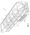
- figure 1 shows a cut-away perspective view of the mobile container according to the invention,
- figure 2 is a perspective side view of the container shown in figure 1, and
- figure 3 shows a perspective cross-section through a variant of the semi-trailer shown in figures 1 and 2.
-
- Figure 1 shows a semi-trailer 1 which comprises a cargo space 2, of which an
end wall 3 and aside wall 4 are shown. A lower part ofside wall 4 consists of asloping partition 5. On the bottom edge this latter adjoins abelt conveyor 6. Cargo space 2 is defined by twoside walls 4, twoend walls 3 andbelt conveyor 6 and is open at the top. Goods for transporting such as potatoes, onions or other tubers, cereals, granules and so on are poured into semi-trailer 1 via the opened top of cargo space 2. - By rotating a return roller 7
belt conveyor 6 is moved and goods can be discharged from cargo space 2. For the purpose of rotation the return roller 7 can be connected to an external drive, but it is also possible to accommodate the drive in return roller 7. Since the static load ofbelt conveyor 6 must remain limited, a protective hood 8 is placed abovebelt conveyor 6 which can take a major part of the weight of goods heaped high in cargo space 2. Connectingpanels 9 are placed in cargo space 2 in order to increase the rigidity of semi-trailer 1. These connectingpanels 9 connect theopposite side walls 4 and simultaneously form the support for protective hood 8. It is also possible to separate this functionality and to fix protective hood 8 in cargo space 2 with separate supports. The upper part of connectingpanels 9 is formed such that a sheet placed over cargo space 2 slopes slightly towardsside walls 4 so that rainwater cannot collect on such a sheet. - By having
side walls 4 form part of a self-supporting construction good use is made of the material which is in any case required at that location. The slopingpartitions 5 must anyway take a strong form in respect of the products falling thereon. The upper part ofside walls 4 must also have a sturdiness such that they can withstand the pressure of the goods situated in cargo space 2. It is possible to make the walls or components thereof even more rigid and if necessary provide them with flanges. Since the bottom edge of eachsloping partition 5 will be heavily loaded becauseconveyor belt 6 is suspended therefrom and also has a bearing function, the edge can be provided with a steel Z- or other profile. Other edges can also be strengthened with steel profiles. - Situated under cargo space 2 is a
construction 11 with which for instance skirts 12, alighting beam 13 and return rollers 7 can be supported.Wheels 24 engage via an axle housing (not shown in this figure) on bothconstruction 11 and cargo space 2. Cargo space 2 is however embodied such that it can also be carried as separate container with a semi-trailer. The separate container can herein be fastened to the semi-trailer with for instance bolts. - Figure 2 shows semi-trailer 1 in side view, wherein is clearly shown that skirts 12 connect onto
side wall 4 such that semi-trailer 1 has a wholly flat side, which gives a very modern appearance. This figure also shows arear end wall 14 in which is arranged anopening 15 which enables discharge of goods by means ofconveyor belt 6. Therear end wall 14 takes a double-walled form so that storage space is created for building in control equipment, whileplatforms 16 are also arranged therein which can be accessed by operative personnel. - Figure 3 shows two
opposite side walls 4 which are mutually connected by means of apull rod 17. Arranged for this purpose onside walls 4 areears 18 which engage onside walls 4 over a greater length. Thepull rod 17 ten connects onto these strengthenedears 18. Also shown clearly in this figure is that the transitions inside walls 4, for instance tosloping partitions 5, are all provided with rounded corners, which enables efficient cleaning of the construction.Belt conveyor 6 is supported by wedge-shaped supportingmembers 19, which are likewise easy to clean. Wedge-shaped supportingmembers 19 connect ontoside walls 4 and prevent large quantities of sand, clay and so on remaining behind after transport of a cargo of for instance potatoes with adhering soil remnants. The significant advantage hereof is that tons of sand, clay and so on will not adhere to the semi-trailer, as is the case in existing potato trailers. This also reduces the transport weight of semi-trailer 1. - Although the invention is elucidated with reference to only a few embodiments, it will be apparent to all that the invention is not limited to the described and shown embodiments. On the contrary, many variations are still possible for the skilled person within the scope of the invention.
Claims (13)
- Mobile container for goods transport by road such as a semi-trailer or trailer, comprising two standing side walls which enclose on a longitudinal side a converging discharge channel, two end walls connected to the side walls, a conveyor connecting onto the discharge channel for discharge of products, a substructure with at least one wheel pair, and coupling means for connecting the mobile container to a tractor vehicle, wherein at least the side walls are manufactured from a plastic and the assembled side walls and end walls form a self-supporting construction.
- Container as claimed in claim 1, wherein the side wails are manufactured from fibre-reinforced plastic.
- Container as claimed in claim 1 or 2, wherein connecting panels engaging over a determined length onto the side walls are placed between the side walls.
- Container as claimed in claim 3, wherein the connecting panels are manufactured from plastic, preferably fibre-reinforced plastic.
- Container as claimed in any of the foregoing claims, wherein the conveyor is an endless belt conveyor.
- Container as claimed in any of the foregoing claims, wherein a protective hood is arranged between the standing side walls at a distance from the discharge channel.
- Container as claimed in claim 6, wherein the protective hood is elongate and the longitudinal sides of the protective hood are located closer to the discharge channel than the part of the protective hood located between the longitudinal sides.
- Container as claimed in claim 7, wherein the protective hood is manufactured from plastic, preferably fibre-reinforced plastic.
- Container as claimed in any of the foregoing claims, wherein at least one of the end sides is provided with an opening at the height of the conveyor for passage of discharged goods.
- Container as claimed in any of the foregoing claims, wherein on of the end sides is provided with recesses for accommodating operating means of the container.
- Container as claimed in any of the foregoing claims, wherein at least one end side is manufactured from plastic, preferably fibre-reinforced plastic.
- Container as claimed in any of the foregoing claims, wherein the side walls, end sides, panels and supports of the protective hood are mutually connected such that they enclose rounded corners.
- Container as claimed in any of the claims 5-12, wherein the belt of the endless belt conveyor is supported by at least one wedge-shaped supporting member.
Applications Claiming Priority (2)
| Application Number | Priority Date | Filing Date | Title |
|---|---|---|---|
| NL1010398A NL1010398C2 (en) | 1998-10-26 | 1998-10-26 | Mobile holder for transporting goods by road. |
| NL1010398 | 1998-10-26 |
Publications (1)
| Publication Number | Publication Date |
|---|---|
| EP0997342A1 true EP0997342A1 (en) | 2000-05-03 |
Family
ID=19768024
Family Applications (1)
| Application Number | Title | Priority Date | Filing Date |
|---|---|---|---|
| EP99203304A Withdrawn EP0997342A1 (en) | 1998-10-26 | 1999-10-08 | Mobile container for goods transport by road |
Country Status (3)
| Country | Link |
|---|---|
| US (1) | US6345949B1 (en) |
| EP (1) | EP0997342A1 (en) |
| NL (1) | NL1010398C2 (en) |
Cited By (2)
| Publication number | Priority date | Publication date | Assignee | Title |
|---|---|---|---|---|
| EP1197386A1 (en) * | 2000-10-14 | 2002-04-17 | Amos Maschinenfabrik und Anlagenbau GmbH | Grape transporting vehicle with combined discharging device |
| EP3231691A1 (en) | 2016-04-12 | 2017-10-18 | Henschel Engineering Automotive SP. z o.o. | Self-supporting vehicle transport trailer |
Families Citing this family (3)
| Publication number | Priority date | Publication date | Assignee | Title |
|---|---|---|---|---|
| US7748099B2 (en) * | 2007-07-19 | 2010-07-06 | Vanguard National Trailer Corp. | Method for creating cargo container with U-shaped panels |
| MX354836B (en) * | 2014-11-05 | 2018-03-21 | Herzog Railroad Services Inc | Material transport and distribution consist with controlled gated hopper cars and conveyor systems. |
| US11833951B1 (en) * | 2021-04-02 | 2023-12-05 | Conveyor Application Systems, LLC | Conveyor system for vehicle |
Citations (6)
| Publication number | Priority date | Publication date | Assignee | Title |
|---|---|---|---|---|
| DE9201633U1 (en) * | 1992-02-10 | 1992-04-16 | Red River ApS, Aalborg | Semi-trailer trailer |
| US5118244A (en) * | 1989-09-22 | 1992-06-02 | Cook Peter P | Truck body structure and driven moving floor for self-unloading |
| FR2705929A1 (en) * | 1993-06-03 | 1994-12-09 | Tech Service Carrosserie In | Vehicle for transporting loose materials |
| US5472290A (en) * | 1993-06-02 | 1995-12-05 | Altamont, Inc. | Joint with tapered edges |
| EP0783991A1 (en) * | 1996-01-15 | 1997-07-16 | Technische Universiteit Delft | Self-supporting refrigerated truck |
| US5690378A (en) * | 1994-01-31 | 1997-11-25 | Romesburg; R. Bruce | Monocoque transport vehicle |
Family Cites Families (12)
| Publication number | Priority date | Publication date | Assignee | Title |
|---|---|---|---|---|
| US1928859A (en) * | 1929-03-13 | 1933-10-03 | Kutscha Alois | Convertible truck body |
| US2791339A (en) * | 1955-07-05 | 1957-05-07 | William H Sprague | Unloading vehicle |
| US3278056A (en) * | 1963-11-12 | 1966-10-11 | Harlan L Beucler | Conveyor truck-trailer |
| US4005790A (en) * | 1969-08-22 | 1977-02-01 | Arkansas Rock And Gravel Co. | Paving material conveyor system |
| US3876089A (en) * | 1973-05-24 | 1975-04-08 | Clegg Jr Giles | Conveyor equipment, especially cargo loading and unloading equipment for a vehicle |
| US4055265A (en) * | 1976-09-10 | 1977-10-25 | Eisenman Leonard J | Bulk bed |
| US4181743A (en) * | 1976-09-15 | 1980-01-01 | Brumlick George C | Food flavorings and methods for producing same |
| US4106643A (en) * | 1977-03-22 | 1978-08-15 | Mcgehee Wendyl B | Fertilizer spreader box |
| US4601629A (en) * | 1984-06-20 | 1986-07-22 | Zimmerman Harold M | Fine and coarse aggregates conveying apparatus |
| US4790715A (en) * | 1985-04-15 | 1988-12-13 | Alexander Richard E | Dump truck accessory |
| US4925356A (en) * | 1985-06-06 | 1990-05-15 | Snead Edwin D | Self-unloading train for bulk commodities |
| US5102285A (en) * | 1988-11-21 | 1992-04-07 | J. D. Enterprises, Inc. | Trailer with continuous conveyer bed |
-
1998
- 1998-10-26 NL NL1010398A patent/NL1010398C2/en not_active IP Right Cessation
-
1999
- 1999-10-08 EP EP99203304A patent/EP0997342A1/en not_active Withdrawn
- 1999-10-22 US US09/425,771 patent/US6345949B1/en not_active Expired - Fee Related
Patent Citations (6)
| Publication number | Priority date | Publication date | Assignee | Title |
|---|---|---|---|---|
| US5118244A (en) * | 1989-09-22 | 1992-06-02 | Cook Peter P | Truck body structure and driven moving floor for self-unloading |
| DE9201633U1 (en) * | 1992-02-10 | 1992-04-16 | Red River ApS, Aalborg | Semi-trailer trailer |
| US5472290A (en) * | 1993-06-02 | 1995-12-05 | Altamont, Inc. | Joint with tapered edges |
| FR2705929A1 (en) * | 1993-06-03 | 1994-12-09 | Tech Service Carrosserie In | Vehicle for transporting loose materials |
| US5690378A (en) * | 1994-01-31 | 1997-11-25 | Romesburg; R. Bruce | Monocoque transport vehicle |
| EP0783991A1 (en) * | 1996-01-15 | 1997-07-16 | Technische Universiteit Delft | Self-supporting refrigerated truck |
Cited By (4)
| Publication number | Priority date | Publication date | Assignee | Title |
|---|---|---|---|---|
| EP1197386A1 (en) * | 2000-10-14 | 2002-04-17 | Amos Maschinenfabrik und Anlagenbau GmbH | Grape transporting vehicle with combined discharging device |
| EP3231691A1 (en) | 2016-04-12 | 2017-10-18 | Henschel Engineering Automotive SP. z o.o. | Self-supporting vehicle transport trailer |
| WO2017178450A1 (en) | 2016-04-12 | 2017-10-19 | Henschel Engineering Automotive Sp. Z O.O. | Self-supporting vehicle transport trailer |
| RU2733010C2 (en) * | 2016-04-12 | 2020-09-28 | Хенсхель Энджиниринг Аутомотив Сп. З О.О. | Self-carrying trailer for vehicle |
Also Published As
| Publication number | Publication date |
|---|---|
| US6345949B1 (en) | 2002-02-12 |
| NL1010398C2 (en) | 2000-04-27 |
Similar Documents
| Publication | Publication Date | Title |
|---|---|---|
| US6076693A (en) | Molded container assembly for transporting bulk materials | |
| US6722839B2 (en) | Refuse collection body | |
| CA2167251A1 (en) | Grain cart equipped with independently driven drag auger | |
| US6539631B1 (en) | Tapered trailer with horizontal seams and support rails | |
| US6626498B1 (en) | Side-discharge tipper vehicle with side wall flexibly connected to the main body | |
| US6092966A (en) | Multi-purpose dump unit for vehicles | |
| US6345949B1 (en) | Mobile container for goods transport by road | |
| US8215029B2 (en) | Drying apparatus and method of using the same | |
| CA1123026A (en) | Tank trailer | |
| US6589002B2 (en) | Material and waste transportation | |
| US3263844A (en) | Vehicle mounted conveyor | |
| US6095743A (en) | Leveling apparatus for loading and leveling flowable metal chip scrap in shipping container | |
| EP0278339A1 (en) | Vehicle with collapsible tanks for transporting liquid loads,and a mobile floor for transporting solid loads as an alternative to liquid loads | |
| EP2397423B1 (en) | Container system for bulk material | |
| US4319863A (en) | Grain trailer and bin | |
| CA1294651C (en) | Convertible container and vehicle | |
| US3000521A (en) | Conveyor unit | |
| US5971494A (en) | Dual use trailer with hopper bottom | |
| US20060156947A1 (en) | Hopper closure assembly with telescoping gate and method of using same | |
| RU2020102C1 (en) | Garden truck-shovel | |
| KR200316118Y1 (en) | Loading Box Structure of Trailer | |
| CN223494377U (en) | AGV is transported to outdoor grain | |
| US20030021664A1 (en) | Material and waste transportation | |
| AU2001100372B4 (en) | Tipper trailer | |
| US20250135982A1 (en) | Self-unloading modular conveyor device for standard trailers, trucks, and similar transport vehicles, a method of converting a standard trailer, truck, or similar transport vehicle into a self-unloading one; and a method of moving and self-unloading loose material using said self-unloading modular conveyor device |
Legal Events
| Date | Code | Title | Description |
|---|---|---|---|
| PUAI | Public reference made under article 153(3) epc to a published international application that has entered the european phase |
Free format text: ORIGINAL CODE: 0009012 |
|
| AK | Designated contracting states |
Kind code of ref document: A1 Designated state(s): AT BE CH CY DE DK ES FI FR GB GR IE IT LI LU MC NL PT SE |
|
| AX | Request for extension of the european patent |
Free format text: AL;LT;LV;MK;RO;SI |
|
| 17P | Request for examination filed |
Effective date: 20001103 |
|
| AKX | Designation fees paid |
Free format text: AT BE CH CY DE DK ES FI FR GB GR IE IT LI LU MC NL PT SE |
|
| GRAP | Despatch of communication of intention to grant a patent |
Free format text: ORIGINAL CODE: EPIDOSNIGR1 |
|
| STAA | Information on the status of an ep patent application or granted ep patent |
Free format text: STATUS: THE APPLICATION IS DEEMED TO BE WITHDRAWN |
|
| 18D | Application deemed to be withdrawn |
Effective date: 20060503 |