EP0996796B1 - A roof assembly and a method for producing such roof assembly - Google Patents
A roof assembly and a method for producing such roof assembly Download PDFInfo
- Publication number
- EP0996796B1 EP0996796B1 EP98933564A EP98933564A EP0996796B1 EP 0996796 B1 EP0996796 B1 EP 0996796B1 EP 98933564 A EP98933564 A EP 98933564A EP 98933564 A EP98933564 A EP 98933564A EP 0996796 B1 EP0996796 B1 EP 0996796B1
- Authority
- EP
- European Patent Office
- Prior art keywords
- layer
- support
- membrane
- overlay
- connection
- Prior art date
- Legal status (The legal status is an assumption and is not a legal conclusion. Google has not performed a legal analysis and makes no representation as to the accuracy of the status listed.)
- Expired - Lifetime
Links
Images


Classifications
-
- E—FIXED CONSTRUCTIONS
- E04—BUILDING
- E04D—ROOF COVERINGS; SKY-LIGHTS; GUTTERS; ROOF-WORKING TOOLS
- E04D5/00—Roof covering by making use of flexible material, e.g. supplied in roll form
- E04D5/14—Fastening means therefor
- E04D5/149—Fastening means therefor fastening by welding
-
- E—FIXED CONSTRUCTIONS
- E04—BUILDING
- E04D—ROOF COVERINGS; SKY-LIGHTS; GUTTERS; ROOF-WORKING TOOLS
- E04D5/00—Roof covering by making use of flexible material, e.g. supplied in roll form
- E04D5/14—Fastening means therefor
- E04D5/141—Fastening means therefor characterised by the location of the fastening means
- E04D5/142—Fastening means therefor characterised by the location of the fastening means along the edge of the flexible material
Definitions
- the invention relates to a roof assembly comprising a structural support, a waterproof membrane comprising sheets of bituminous membrane material arranged on said support with overlay; wherein the lower layer of the overlay is, exclusively in the peripheral portion of the sheet, in permanent connection with the support; and wherein the upper layer of the overlay is in permanent connection with the lower layer of the overlay.
- a structural support which is usually made of a sheet material that can be secured on a rafter construction or the like structural support.
- the support may also be a supporting sheet material and eg an overlaying heat-insulating layer.
- This support serves as support for a bituminous roofing layer which is permanently connected thereto, eg by welding.
- it may be a full-surface connection, as described eg in DK 136 374 and SE 460 982; or eg elongate connecting strips or the like positioned at intervals transversally to a roofing sheet so as to establish a connection to the support.
- the roofing layer can consist of a single- or multi-layered bituminous roofing material and is typically coated on its top surface with crushed slate, but it may also have another surface.
- a need subsequently arises for covering this roofing layer with a waterproof membrane which is usually, like the roofing material proper, made of a bituminous material.
- Such subsequent coverings with a waterproof membrane can be made eg in accordance with the prior art, wherein membrane sheets are mounted with an overlay and secured to the support. In this context it is known to use two different principles for the attachment of the membrane sheets relative to the roof construction, viz a peripheral connection or full-surface welding/strip welding of the membrane sheets.
- peripheral attachment is generally considerably more expediently established than a full-surface/strip welding. Furthermore, compared to the principle of full-surface/strip welding, the principle of peripheral attachment involves the considerable advantage that a subsequent dismounting of the membrane sheets is considerably less difficult. This is significant in connection with the increasing re-use of such membrane material. For the peripheral attachment, the membrane sheets must generally be dimensioned with more strength. The drawback associated with this in the form of an increased material consumption, however, is amply balanced by the advantage of more expedient mounting and the convenient properties in connection with dismounting.
- An example of peripheral attachment is shown in SE 460 982.
- this is accomplished by the permanent connection between the lower membrane layer in the overlay and the lower layer consisting of a permanent, mutual welded or adhesive connection between support and a peripheral area of the lower membrane layer in the overlay.
- Permanent connection between the support and the lower part of the overlay can be established substantially more expediently by an adhesive or welded connection than by permanent connection by means of attachment means.
- a considerable rationalisation of the roof construction is obtained from a manufacturing point of view, and considerably improved strength conditions are also obtained therefor while maintaining the advantageous properties of the peripheral attachment as regards dismounting.
- the attachment means which may be eg metallic, from the remaining material. This entails a considerable rationalisation of the re-use.
- the roofing layer comprises a bituminous top layer coated with crushed slate or other surface coating
- the side of lower portion of the overlay that faces the bituminous top layer preferably comprises a heat-activatable adhesive layer which will, by the welding connection, establish the permanent connection between the lower membrane layer in the overlay and the roofing layer and hence the permanent connection with the remaining support.
- the invention also relates to a method for use in the construction of a roof as described above by connecting a lower layer of a membrane material in an overlay with a lower layer.
- the method is characterised in that the lower layer in the overlay is in the overlay area connected to the support in a heating process; and in a subsequent depression of the membrane layer towards the roofing layer.
- This heating process is conveniently effected by heat being supplied to the underside of an outer periphery of the membrane layer which forms the lower portion of the overlay, following deposition of the membrane portion on the support, and to the top surface of the lower layer while the heat source is moved in the longitudinal direction of the sheet, and in that, successively, in the same direction and at essentially the same velocity, a depression of the membrane layer towards the lower layer is carried out.
- the method can be exercised in that the heat supply can be effected by use of a hot-air generator with a mouthpiece introduced between the membrane layer and the support, said hot air being blown in at a high velocity.
- the support comprises a roofing layer with a bituminous top layer coated with crushed slate or a similar coating material and the side of the lower portion of the top layer that faces towards the bituminous top layer preferably comprises a heat-activatable adhesive layer
- the blowing-in and subsequent depression causes the coating material to be shifted from the central area of the zone of peripheral welding, whereby a substantially improved connection is obtained between the bituminous material in the roofing layer and the heat-activatable adhesive layer than was otherwise known by welding of membrane sheets with a coated surface.
- a hot-air generator preferably an electrical hot-air generator
- an electric hot-air generator also results in a considerable reduction of the risk of fires erupting compared to the use of gas burners.
- Depression of the membrane layer towards the roofing layer is preferably effected by means of a roll which is conveyed either by hand or in a rack that also carries the heat source.
- the pressure force constitutes 0.4-4.0 N/mm, preferably 0.8-3.0 N/mm.
- the rate of advancement for the heat supplier is preferably such that, at the side of the membrane edge, a bead of heat-activatable adhesive substance will emerge, having a magnitude of 2-20 mm.
- the width of the welding area at the edge corresponds approximately to the width of the overlay, ie it is within the range of 5-15 cm.
- FIG 1 illustrates combining of a membrane layer 3 for mounting on an existing roofing 2 ( Figures 2 and 3).
- the membrane layer comprises a reinforcing layer 11 which has been impregnated and coated with a mixture 12 of bitumen, filler and thermoplastic elastomer; and wherein a layer of crushed slate 13 is arranged on top of this.
- a heat-activatable adhesive substance 14 is provided consisting of bitumen, filler and thermoplastic elastomer.
- the membrane layer is provided with a readily meltable plastics film 15.
- FIG. 2 shows an example of prior art wherein an existing roofing layer 2 mounted on a support 1 of sheet material is coated with a membrane 3,4.
- the roofing material 2 is permanently attached to the support 1 by full-surface welding. However, it may be discrete welding areas, such as elongate connecting strips or peripheral attachment.
- the lower layer of the membrane material 3 is connected to the support 1 by means of an attachment means 21.
- the upper layer of the membrane material 4 is subsequently arranged in overlay relative to the lower membrane material layer 3, and is herein welded thereto by peripheral welding 5.
- the head of such attachment means covers a limited area and therefore, with a view to the power influences exerted thereon, the membrane layer 3 must be dimensioned in accordance with the size of the head of the attachment means or the number thereof. Equally obviously, this known method of attachment involves penetration of the existing roofing material 2 which creates access for moisture below the roofing material.
- Figure 3 illustrates an example of the roof construction according to the invention wherein a support 1 has a roofing material 2 mounted thereon by full welding; and wherein the attachment of membrane material 3 relative to the support 1 has been accomplished by peripheral welding relative to the existing roofing material 2, thus producing an indirect connection.
- the superjacent membrane sheet 4 is, like in the prior art, connected by welding to the lower membrane sheet 3 in an overlay.
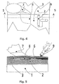
- FIG 4 shows a section of a roof construction while exercising the method for forming the roof construction illustrated in Figure 3.
- the membrane layer 3 has been rolled onto the roofing material 2 and the mouthpiece 8 of a heat supplier 7 has been inserted into the peripheral area below the membrane layer 3 where it is conveyed to the left in Figures 4 and 5 during the welding process.
- a roll 9 is conveyed manually across the welding area and the welding area is compressed.
- Figure 6 illustrates an alternative embodiment of the method according to the invention wherein the subsequent compression of the welding place is effected by means of a more heavy roll 10 mounted on a not shown rack which also carries the hot-air supplier 7. Owing to the mounting on a rack which is advanced to the left in the drawing, there is a need for a heavier roll, since it is not possible to exert a manual pressure on the welding site. The same will appear from Figure 7 which is a sectional view through the construction shown in Figure 6.
- the roofing layer preferably comprises a bituminous top layer coated with crushed slate or the like coated material, and the side of the lower portion of the overlay which faces towards the bituminous top layer preferably comprises a heat-activatable adhesive layer.
- This coated coating presents particularly difficult conditions in a welding connection.
- the blowing-in of hot air and the subsequent depression effects a shifting of the coating material in the welding area, and this enables a tear strength in the connecting area which substantially exceeds the tear strengths otherwise obtainable between roofing and membrane.
Description
Claims (11)
- A roof construction comprising a support (1) and a waterproof membrane (3,4) comprising sheets of bituminous membrane material arranged on the support with overlay, wherein the lower layer (3) of the overlay is exclusively at the outer periphery of said sheet in permanent connection with the support; and wherein the upper layer of the overlay is in permanent connection (5) with the lower layer (3) of the overlay, characterized in that the permanent connection between the lower membrane layer (3) in the overlay and the lower layer (1) consists in a permanent, mutual welded or adhesive connection (6) at the periphery of the lower membrane layer (3).
- A roof construction according to claim 1, characterized in that the structural support (1) is composed of a lower structural part and a heat-insulating upper part.
- A roof construction according to claim 1 or 2, characterized in that the support (1) comprises a bituminous roofing layer (2) arranged on the lower structural portion or on an insulating layer in direct or indirect permanent connection with the structural portion of the support; wherein the permanent peripheral connection between the support and the bituminous membrane is formed between the roofing layer (2) and the membrane layer (3).
- A roof construction according to claim 3, characterized in that the roofing layer (2) comprises a bituminous top layer coated with slate or other surface coating; and in that the side of the lower portion (3) of the overlay that faces towards the support comprises a heat-activatable adhesive layer.
- A roof construction according to any one of claims 1-4, characterized in that transversally to the permanent peripheral connection (6) between support (1) and the lower membrane layer (3) of the overlay is provided with passages so as to establish flow-connection through the peripheral connection (6) for pressure equalisation between the spaces between membrane and support that are covered by the membrane sheets (3,4).
- A method for use in the formation of a roof construction according to claims 1-5, wherein a lower membrane sheet (3) in an overlay is to be connected to a support (1) exclusively at a peripheral area, characterized in that the connection of the lower membrane sheet in the overlay to the support is effected by the lower membrane sheet in a peripheral area being permanently connected to the support by a heating process; and a subsequent depression of the membrane sheet (3).
- A method according to claim 6, characterized in that the membrane sheet (3) of which an outer peripheral area forms the lower part of the overlay is laid onto the support; and in that heat is supplied to the underside of this outer periphery and to the top surface of the support, the heat source being moved in the longitudinal direction of the sheet; and in that, successively and in the same direction and with substantially the same rate, a depression of the membrane sheet (3) is performed.
- A method according to claim 7, characterized in that the heat supply is effected by use of a hot-air generator with a mouthpiece introduced between membrane layer (3) and support (2), wherein the hot air is blown out at a high rate.
- A method according to claim 7, characterized in that the depression is carried out by means of a roll which is conveyed either by hand or in a rack which also carries the heat supplier.
- A method according to claims 6-9, characterized in that the depression is effected by a linear pressure within the range of 0.4-4.0 N/mm, preferably within the range of 0.8-3.0 N/mm.
- A method according to any one of claims 6-10, characterized in that, at discrete locations in the permanent peripheral connection between lower layer (2) and the lower membrane sheet (3), passages are provided over the entire width of the permanent peripheral connection, wherein the passage-forming material is eg a felt material.
Applications Claiming Priority (3)
| Application Number | Priority Date | Filing Date | Title |
|---|---|---|---|
| DK88097A DK173299B1 (en) | 1997-07-18 | 1997-07-18 | Roof structure as well as methods for use in forming such a n |
| DK88097 | 1997-07-18 | ||
| PCT/DK1998/000309 WO1999004114A1 (en) | 1997-07-18 | 1998-07-06 | A roof assembly and a method for producing such roof assembly |
Publications (2)
| Publication Number | Publication Date |
|---|---|
| EP0996796A1 EP0996796A1 (en) | 2000-05-03 |
| EP0996796B1 true EP0996796B1 (en) | 2003-10-01 |
Family
ID=8098573
Family Applications (1)
| Application Number | Title | Priority Date | Filing Date |
|---|---|---|---|
| EP98933564A Expired - Lifetime EP0996796B1 (en) | 1997-07-18 | 1998-07-06 | A roof assembly and a method for producing such roof assembly |
Country Status (5)
| Country | Link |
|---|---|
| EP (1) | EP0996796B1 (en) |
| AU (1) | AU8333498A (en) |
| DK (1) | DK173299B1 (en) |
| NO (1) | NO313760B1 (en) |
| WO (1) | WO1999004114A1 (en) |
Family Cites Families (5)
| Publication number | Priority date | Publication date | Assignee | Title |
|---|---|---|---|---|
| DK136374C (en) * | 1975-05-05 | 1981-08-31 | Villadsens Fab As Jens | PROCEDURE FOR PREPARING A ROOF COVER ON A ROOF SURFACE |
| US4239581A (en) * | 1979-04-23 | 1980-12-16 | Lang John N | Apparatus for sealing lap joints of fusible roofing sheets |
| JPS6059184A (en) * | 1983-09-12 | 1985-04-05 | Tajima Le-Fuingu Kk | Asphalt-based laminated roofing sheet |
| DE8700565U1 (en) * | 1986-12-05 | 1987-04-02 | Roland-Werke Dachbaustoffe U. Bauchemie Algostat Gmbh & Co, 2807 Achim, De | |
| SE460982B (en) * | 1988-01-25 | 1989-12-11 | Vaernamo Isolerduk Ab | Roof lining |
-
1997
- 1997-07-18 DK DK88097A patent/DK173299B1/en not_active IP Right Cessation
-
1998
- 1998-07-06 AU AU83334/98A patent/AU8333498A/en not_active Abandoned
- 1998-07-06 WO PCT/DK1998/000309 patent/WO1999004114A1/en active IP Right Grant
- 1998-07-06 EP EP98933564A patent/EP0996796B1/en not_active Expired - Lifetime
-
2000
- 2000-01-17 NO NO20000214A patent/NO313760B1/en not_active IP Right Cessation
Also Published As
| Publication number | Publication date |
|---|---|
| DK88097A (en) | 1999-01-19 |
| NO20000214D0 (en) | 2000-01-17 |
| DK173299B1 (en) | 2000-06-20 |
| NO20000214L (en) | 2000-03-17 |
| NO313760B1 (en) | 2002-11-25 |
| AU8333498A (en) | 1999-02-10 |
| EP0996796A1 (en) | 2000-05-03 |
| WO1999004114A1 (en) | 1999-01-28 |
Similar Documents
| Publication | Publication Date | Title |
|---|---|---|
| US6187122B1 (en) | Dual-weld roof membrane welding apparatus and method of using same | |
| US20050196253A1 (en) | Plastic/metal composite stress plate and method of using same for securing a thermoplastic roof membrane to roof deck | |
| EP0674739B1 (en) | Method of laying roofing felt and means therefor | |
| CA2478222C (en) | Single ply roofing systems and methods of constructing them | |
| US5884446A (en) | Roof having improved base sheet | |
| US3121649A (en) | Method of installing roof insulation on buildings | |
| US7069698B2 (en) | Method and apparatus for coupling structures to roofing | |
| US6764260B1 (en) | Plastic/metal composite batten bar and method of using same for securing a thermoplastic roof membrane to a roof deck | |
| JPS6364728A (en) | Method of heat-sealing thermoplastic film | |
| US5479753A (en) | Process for sealing a sloped metal roof | |
| JPH0688403A (en) | Roofing roof sheathing | |
| US6537402B2 (en) | Membrane welding apparatus including a visual seam marker | |
| US20050183261A1 (en) | Method of securing a membrane to a deck | |
| US20020074084A1 (en) | Method for attaching thermoplastic strips to thermoplastic roof membranes | |
| US6875162B2 (en) | Stand-up roller apparatus | |
| CN114482418A (en) | Embedded double-curved-surface continuous welding stainless steel metal roof and construction method thereof | |
| EP0996796B1 (en) | A roof assembly and a method for producing such roof assembly | |
| JPH0254053A (en) | Insulating and water-proofing work | |
| JP2000034808A (en) | Heat insulating and waterproof board and heat insulating and waterproof structure of roof using the same | |
| US5543003A (en) | Torch-on roofing degranulator system | |
| WO1993009310A1 (en) | Method of supporting a roof and the like | |
| JP2805135B2 (en) | Metal sheet roofing sheet waterproofing device | |
| AU659162B2 (en) | Insulating roof panel, process and device for the manufacture thereof | |
| US4654109A (en) | Hot trowel device and method | |
| EP0638696A1 (en) | Roofcovering material |
Legal Events
| Date | Code | Title | Description |
|---|---|---|---|
| PUAI | Public reference made under article 153(3) epc to a published international application that has entered the european phase |
Free format text: ORIGINAL CODE: 0009012 |
|
| 17P | Request for examination filed |
Effective date: 20000111 |
|
| AK | Designated contracting states |
Kind code of ref document: A1 Designated state(s): FI GB |
|
| GRAH | Despatch of communication of intention to grant a patent |
Free format text: ORIGINAL CODE: EPIDOS IGRA |
|
| GRAS | Grant fee paid |
Free format text: ORIGINAL CODE: EPIDOSNIGR3 |
|
| GRAA | (expected) grant |
Free format text: ORIGINAL CODE: 0009210 |
|
| AK | Designated contracting states |
Kind code of ref document: B1 Designated state(s): FI GB |
|
| REG | Reference to a national code |
Ref country code: GB Ref legal event code: FG4D |
|
| PLBE | No opposition filed within time limit |
Free format text: ORIGINAL CODE: 0009261 |
|
| STAA | Information on the status of an ep patent application or granted ep patent |
Free format text: STATUS: NO OPPOSITION FILED WITHIN TIME LIMIT |
|
| 26N | No opposition filed |
Effective date: 20040702 |
|
| PGFP | Annual fee paid to national office [announced via postgrant information from national office to epo] |
Ref country code: FI Payment date: 20140710 Year of fee payment: 17 |
|
| PGFP | Annual fee paid to national office [announced via postgrant information from national office to epo] |
Ref country code: GB Payment date: 20140702 Year of fee payment: 17 |
|
| GBPC | Gb: european patent ceased through non-payment of renewal fee |
Effective date: 20150706 |
|
| PG25 | Lapsed in a contracting state [announced via postgrant information from national office to epo] |
Ref country code: GB Free format text: LAPSE BECAUSE OF NON-PAYMENT OF DUE FEES Effective date: 20150706 |
|
| PG25 | Lapsed in a contracting state [announced via postgrant information from national office to epo] |
Ref country code: FI Free format text: LAPSE BECAUSE OF NON-PAYMENT OF DUE FEES Effective date: 20150706 |