EP0996748B1 - Pivoting device with arm and control rod - Google Patents
Pivoting device with arm and control rod Download PDFInfo
- Publication number
- EP0996748B1 EP0996748B1 EP98939597A EP98939597A EP0996748B1 EP 0996748 B1 EP0996748 B1 EP 0996748B1 EP 98939597 A EP98939597 A EP 98939597A EP 98939597 A EP98939597 A EP 98939597A EP 0996748 B1 EP0996748 B1 EP 0996748B1
- Authority
- EP
- European Patent Office
- Prior art keywords
- control rod
- boom
- arm
- cantilever arm
- swivelling device
- Prior art date
- Legal status (The legal status is an assumption and is not a legal conclusion. Google has not performed a legal analysis and makes no representation as to the accuracy of the status listed.)
- Expired - Lifetime
Links
Images


Classifications
-
- C—CHEMISTRY; METALLURGY
- C21—METALLURGY OF IRON
- C21B—MANUFACTURE OF IRON OR STEEL
- C21B7/00—Blast furnaces
- C21B7/12—Opening or sealing the tap holes
Definitions
- the invention relates to a swivel device with boom, for Swiveling a work organ between a first and a second Position, and with a control rod for aligning the work organ in Dependence of the angular position of the boom.
- a swivel device with boom, for Swiveling a work organ between a first and a second Position, and with a control rod for aligning the work organ in Dependence of the angular position of the boom.
- Such a device will for example in a tap hole drilling machine or tap hole tapping machine on Blast furnace used.
- a classic tap hole drilling machine has a support structure in which a Boom with a first end is pivotally mounted about a first axis.
- a swivel drive creates a swiveling movement of the boom around it first axis, for example from a rest position to a first working position in front of a first tap hole, or in a second working position in front of one second tap hole, and each back to the rest position.
- a drill carriage is pivotable about a second axis with the second end of the boom connected.
- a control rod is about a first joint with a fixed point on the support structure and via a second joint with the swivel Drill mount connected so that a pivoting movement of the boom around the first axis, a pivoting movement of the drill carriage around the second axis generated.
- This control rod can consequently be used to align the Determine the drill carriage depending on the angular position of the boom.
- a disadvantage of these swivel devices is that the control rod Boom crosses when swiveling the drill carriage. It follows that this Control rod can be arranged either above or below the boom must, of course, what the space requirement (i.e. the required free height) for Swiveling of the boom increased. This can be especially true Space problems result when a tap hole drilling machine and a Taphole tamping machine arranged on the same side of the tapping trough are, and the boom of the tap hole drilling machine when pivoting the Taphole cannon must go under or over.
- Such a constellation is for example, described in U.S. Patent 4,195,825.
- the present invention has for its object a To create swivel device with boom and control rod, which a less free height needed to pivot the boom.
- a swivel device for carrying a work organ (such as a drill carriage or a cannon), in known Way, a support structure, a boom and a control rod.
- a work organ such as a drill carriage or a cannon
- On first end of the boom is pivotally mounted in the support structure, so that the boom is pivotable about a first axis relative to the support structure.
- the Work organ is pivotally attached to the second end of the boom, so that it is pivotable relative to the boom about a second axis.
- the Control rod is with a first end on the pivotable working member articulated. It is an important feature of the present invention that second end of the control rod is not as usual at a fixed point of the Support structure, but is hinged to a four-link gearbox.
- This four-link transmission includes the support structure as a frame and the boom as driven link.
- a first link is on the support structure hinged, and a second link is hinged to the boom. These two links are hinged together so that the four-link gearbox is closed.
- the control rod is included its second end on the first or second link of the Gearbox articulated.
- FIG. 1 shows a top view of the casting platform 8 of a blast furnace 12, a tap hole drilling machine 10 in the rest position, to the side of one Tapping gutter 13 of the blast furnace 12.
- This tap hole drilling machine 10 consists in essentially from a swivel device 14 according to the invention and a well-known drill carriage 16. The latter is not described further here.
- the pivoting device 14 comprises a support structure 18 for a boom 20.
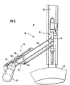
- This support structure can, as shown in Figure 3, for example, under a stage 21, which surrounds the blast furnace 12, be suspended. However, it could also be set up on the casting platform 8.
- One end of the boom 20 is in this Support structure 18 pivotally mounted.
- the location of the Pivot axis of the boom 20 in the support structure 18 through the Reference numeral 22 shown.
- the Drill mount 16 pivotally suspended.
- the location of the pivot axis of the Drill mount 16 in the boom 20 is shown by reference numeral 24.
- As a swivel drive of the boom is preferably a hydraulic motor, such as Example, a double-acting hydraulic cylinder 28 used.
- This Hydraulic cylinder 28 is Piston end is articulated on the boom 20.
- This hydraulic cylinder 28 thus enables Swiveling the boom 20 about its pivot axis 22, between the in the rest position shown in Figure 1, away from the tapping channel 13, and in Figure 2 shown working position, in the axial extension of the tap hole, directly above the launder 13.
- a control rod 30 is connected to the drilling mount 16 via a first swivel joint 32 connected.
- the other end is this control rod articulated to the support structure.
- the Control rod in the well-known tap hole drilling machine the drill carriage Swiveling between the rest position and the working position crosses, or in other words, that the boom pivots the control rod must run over or under.
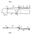
- the gear 34 is described in more detail with reference to FIGS. 4 and 5. It is a four-link transmission, the support structure 18 the Frame and the boom 20 form the driven member of the transmission.
- a first connecting link 36 is connected to the supporting structure via a swivel joint 38 18 connected.
- a second connecting member 40 is connected via a swivel joint 42 connected to the boom 20.
- These two links 36 and 40 are connected to each other via a swivel 40 so that they are the four-part Close transmission 34.
- the second end of the control rod 30 is by means of a Swivel joint 46 with the second connecting member 40 of the transmission 34 connected.
- control rod 30 the boom 20 when pivoting does not cross.
- the precise alignment of the drilling mount 16 in the working position is advantageous fixed by a length adjustment of the control rod 30.
- This The length of the control rod 30 can be adjusted, for example, by means of a and unscrewable threaded rod 48.
- the undercarriage Cantilever 20 When swiveling between its rest and work position, the undercarriage Cantilever 20 recognizes the first connecting link 36. From FIGS. 1 and 2 however, that the area of the boom 20 is that of the first Link 36 must be pivoted through, to a relative short section 50 in the immediate vicinity of the support structure 18 is limited. As can be seen from Figure 3, the connecting member 36 is in this Section 50 in a space between the bottom of the stage 21 and the Top of the boom 20 arranged. Right behind this area 50, the limit of which is indicated in FIG. 3 by the broken line 52, there is no longer any need to be provided above the boom 20. The boom 20 can consequently be graded in height, as shown in FIG. 3 with its front end 54 higher than its rear end 50.
- the Control rod 30 is located laterally in the swivel range of front end 54 (i.e. in a space that, when the boom 20 is pivoted, between Lower edge 56 and upper edge 58 of the front end 54 of the boom 20 lies). Consequently, it does not require any additional effort when pivoting Free space.
- reference numeral 60 shows that below the boom 20 swiveling taphole cannon. It is clearly evident that without one arrangement of the control rod 30 according to the invention, the free height between Platform and casting platform would not be sufficient to the boom 20 with the To pass under taphole cannon 60.
- Links 36 and 40 is just one of many possibilities. So for example, these links 36, 40 could be below the boom 20 may be arranged. It is also conceivable for the boom 20 in the area 50 to be provided with a recess through which the connecting member 36 is carried out. Such a recess is shown schematically in FIG a dashed line 62 is indicated. In these two cases, the Boom 20 of course not to be graded in height.
Abstract
Description
Die Erfindung betrifft eine Schwenkvorrichtung mit Ausleger, zum Verschwenken eines Arbeitsorgans zwischen einer ersten und einer zweiten Stellung, und mit einer Steuerstange zum Ausrichten des Arbeitsorgans in Abhängigkeit der Winkelstellung des Auslegers. Eine solche Vorrichtung wird zum Beispiel in einer Stichlochbohrmaschine oder Stichlochstopfmaschine am Hochofen eingesetzt.The invention relates to a swivel device with boom, for Swiveling a work organ between a first and a second Position, and with a control rod for aligning the work organ in Dependence of the angular position of the boom. Such a device will for example in a tap hole drilling machine or tap hole tapping machine on Blast furnace used.
Eine klassische Stichlochbohrmaschine weist eine Tragstruktur auf, in der ein Ausleger mit einem ersten Ende um eine erste Achse schwenkbar gelagert ist. Ein Schwenkantrieb erzeugt eine Schwenkbewegung des Auslegers um diese erste Achse, zum Beispiel aus einer Ruhestellung in eine erste Arbeitsstellung vor einem ersten Stichloch, bzw. in eine zweite Arbeitsstellung vor einem zweiten Stichloch, und jeweils zurück in die Ruhestellung. Eine Bohrlafette ist um eine zweite Achse schwenkbar mit dem zweiten Ende des Auslegers verbunden. Eine Steuerstange ist über ein erstes Gelenk mit einem Festpunkt an der Tragstruktur und über ein zweites Gelenk mit der schwenkbaren Bohrlafette verbunden, so daß eine Schwenkbewegung des Auslegers um die erste Achse, eine Schwenkbewegung der Bohrlafette um die zweite Achse erzeugt. Durch diese Steuerstange läßt sich folglich die Ausrichtung der Bohrlafette in Abhängigkeit der Winkelstellung des Auslegers festlegen.A classic tap hole drilling machine has a support structure in which a Boom with a first end is pivotally mounted about a first axis. A swivel drive creates a swiveling movement of the boom around it first axis, for example from a rest position to a first working position in front of a first tap hole, or in a second working position in front of one second tap hole, and each back to the rest position. A drill carriage is pivotable about a second axis with the second end of the boom connected. A control rod is about a first joint with a fixed point on the support structure and via a second joint with the swivel Drill mount connected so that a pivoting movement of the boom around the first axis, a pivoting movement of the drill carriage around the second axis generated. This control rod can consequently be used to align the Determine the drill carriage depending on the angular position of the boom.
Nachteilig bei diesen Schwenkvorrichtungen ist, daß die Steuerstange den Ausleger beim Verschwenken der Bohrlafette kreuzt. Hieraus erfolgt, daß diese Steuerstange entweder oberhalb oder unterhalb des Auslegers angeordnet sein muß, was natürlich den Platzbedarf (d.h. die benötigte freie Höhe) zum Verschwenken des Auslegers erhöht. Dies kann insbesondere dann zu Platzproblemen führen, wenn eine Stichlochbohrmaschine und eine Stichlochstopfmaschine auf der gleichen Seite der Abstichrinne angeordnet sind, und der Ausleger der Stichlochbohrmaschine beim Verschwenken die Stichlochstopfkanone unter- bzw. überfahren muß. Eine solche Konstellation ist zum Beispiel in der US Patentschrift 4,195,825 beschrieben. A disadvantage of these swivel devices is that the control rod Boom crosses when swiveling the drill carriage. It follows that this Control rod can be arranged either above or below the boom must, of course, what the space requirement (i.e. the required free height) for Swiveling of the boom increased. This can be especially true Space problems result when a tap hole drilling machine and a Taphole tamping machine arranged on the same side of the tapping trough are, and the boom of the tap hole drilling machine when pivoting the Taphole cannon must go under or over. Such a constellation is for example, described in U.S. Patent 4,195,825.
Der vorliegenden Erfindung liegt die Aufgabe zugrunde, eine Schwenkvorrichtung mit Ausleger und Steuerstange zu schaffen, welche eine geringere freie Höhe zum Verschwenken des Auslegers benötigt.The present invention has for its object a To create swivel device with boom and control rod, which a less free height needed to pivot the boom.
Diese Aufgabe wird erfindungsgemäß durch eine Schwenkvorrichtung nach Anspruch 1 gelöst.This object is achieved by a swivel device Claim 1 solved.
Eine erfindungsgemäße Schwenkvorrichtung zum Tragen eines Arbeitsorgans (wie zum Beispiel eine Bohrlafette oder eine Stopfkanone) umfaßt, in bekannter Art und Weise, eine Tragstruktur, einen Ausleger und eine Steuerstange. Ein erstes Ende des Auslegers ist schwenkbar in der Tragstruktur gelagert, so daß der Ausleger relativ zur Tragstruktur um eine erste Achse schwenkbar ist. Das Arbeitsorgan ist schwenkbar am zweiten Ende des Auslegers befestigt, so daß es relativ zum Ausleger um eine zweite Achse schwenkbar ist. Die Steuerstange ist mit einem ersten Ende an dem schwenkbaren Arbeitsorgan angelenkt. Es ist ein wichtiges Merkmal der vorliegenden Erfindung, daß das zweite Ende der Steuerstange nicht wie üblich an einem Festpunkt der Tragstruktur, sondern an einem viergliedrigen Getriebe angelenkt ist. Dieses viergliedrige Getriebe umfaßt die Tragstruktur als Gestell und den Ausleger als angetriebenes Glied. Ein erstes Verbindungsglied ist an der Tragstruktur angelenkt, und ein zweites Verbindungsglied ist an dem Ausleger angelenkt. Diese beiden Verbindungsglieder sind gelenkig miteinander verbunden, so daß das viergliedrige Getriebe geschlossen ist. Die Steuerstange ist hierbei mit ihrem zweiten Ende an dem ersten oder zweiten Verbindungsglied des Getriebes angelenkt. In dieser erfindungsgemäßen Schwenkvorrichtung liegt, beim Verschwenken des Auslegers, der Anlenkpunkt des zweiten Endes der Steuerstange immer auf der gleichen Seite des Auslegers, so daß die Steuerstange den Ausleger beim Verschwenken nicht kreuzt. Hierdurch wird eine Schwenkvorrichtung geschaffen die - zumindest im Schwenkbereich der Steuerstange - eine geringere freie Höhe zum Verschwenken des Auslegers benötigt.A swivel device according to the invention for carrying a work organ (such as a drill carriage or a cannon), in known Way, a support structure, a boom and a control rod. On first end of the boom is pivotally mounted in the support structure, so that the boom is pivotable about a first axis relative to the support structure. The Work organ is pivotally attached to the second end of the boom, so that it is pivotable relative to the boom about a second axis. The Control rod is with a first end on the pivotable working member articulated. It is an important feature of the present invention that second end of the control rod is not as usual at a fixed point of the Support structure, but is hinged to a four-link gearbox. This four-link transmission includes the support structure as a frame and the boom as driven link. A first link is on the support structure hinged, and a second link is hinged to the boom. These two links are hinged together so that the four-link gearbox is closed. The control rod is included its second end on the first or second link of the Gearbox articulated. In this swivel device according to the invention, when pivoting the boom, the pivot point of the second end of the Control rod always on the same side of the boom so that the Control rod does not cross the boom when swiveling. This will created a swivel device - at least in the swivel range of the Control rod - a lower free height for pivoting the boom needed.
Ein Ausführungsbeispiel der Erfindung wird anhand der beiliegenden Zeichnungen näher beschrieben. Es zeigt:
- Figur 1:
- eine Draufsicht auf eine Stichlochbohrmaschine mit einer erfindungsgemäßen Schwenkvorrichtung, in Ruhestellung vor einem Hochofen;
- Figur 2:
- eine Draufsicht auf die Stichlochbohrmaschine der Figur 1, in Arbeitsstellung vor dem Hochofen;
- Figur 3:
- eine Ansicht des Auslegers einer erfindungsgemäßen Stichlochbohrmaschine, der von einer Stichlochstopfmaschine unterfahren wird (die Bohrlafette und der Ausleger der Stichlochstopfmaschine sind in der Figur nicht gezeigt);
- Figur 4:
- eine Detailansicht eines Getriebes nach Figur 1;
- Figur 5:
- eine Seitenansicht des in Figur 4 gezeigten Getriebes.
- Figure 1:
- a plan view of a tap hole drilling machine with a swivel device according to the invention, in the rest position in front of a blast furnace;
- Figure 2:
- a plan view of the tap hole drilling machine of Figure 1, in the working position in front of the blast furnace;
- Figure 3:
- a view of the boom of a tap hole drilling machine according to the invention, which is driven under by a tap hole tamping machine (the drill carriage and the boom of the tap hole tamping machine are not shown in the figure);
- Figure 4:
- a detailed view of a transmission according to Figure 1;
- Figure 5:
- a side view of the transmission shown in Figure 4.
In Figur 1 sieht man, in einer Draufsicht auf die Gießbühne 8 eines Hochofens
12, eine Stichlochbohrmaschine 10 in Ruhestellung, seitlich von einer
Abstichrinne 13 des Hochofens 12. Diese Stichlochbohrmaschine 10 besteht im
wesentlichen aus einer erfindungsgemäßen Schwenkvorrichtung 14 und einer
an sich bekannten Bohrlafette 16. Letztere wird hier weiter nicht beschrieben.FIG. 1 shows a top view of the
Die Schwenkvorrichtung 14 umfaßt eine Tragstruktur 18 für einen Ausleger 20.
Diese Tragstruktur kann, wie in Figur 3 gezeigt, zum Beispiel unter einer Bühne
21, die den Hochofen 12 umgibt, aufgehängt sein. Sie könnte jedoch ebenfalls
auf der Gießbühne 8 aufgestellt sein. Ein Ende des Auslegers 20 ist in dieser
Tragstruktur 18 schwenkbar gelagert. In Figur 1 wird die Lage der
Schwenkachse des Auslegers 20 in der Tragstruktur 18 durch das
Bezugszeichen 22 gezeigt. An dem freien Ende des Auslegers 20 ist die
Bohrlafette 16 schwenkbar aufgehängt. Die Lage der Schwenkachse der
Bohrlafette 16 in dem Ausleger 20 wird durch das Bezugszeichen 24 gezeigt.
Als Schwenkantrieb des Auslegers wird vorzugsweise ein Hydromotor, wie zum
Beispiel ein doppeltwirkender Hydrozylinder 28, eingesetzt. Ein Ende dieses
Hydrozylinders 28, in der gezeigten Ausführung handelt es sich um das
Kolbenende, ist am Ausleger 20 angelenkt. Das zweite Ende des Hydrozylinder
28, in der gezeigten Ausführung handelt es sich um den Zylinderfuß, ist an der
Tragstruktur 18 angelenkt. Dieser Hydrozylinder 28 ermöglicht somit ein
Verschwenken des Auslegers 20 um seine Schwenkachse 22, zwischen der in
der Figur 1 gezeigten Ruhestellung, abseits der Abstichrinne 13, und der in
Figur 2 gezeigten Arbeitsstellung, in axialer Verlängerung des Stichlochs, direkt
oberhalb der Abstichrinne 13.The
Eine Steuerstange 30 ist über ein erstes Drehgelenk 32 mit der Bohrlafette 16
verbunden. In den bekannten Stichlpchbohrmaschinen ist das andere Ende
dieser Steuerstange an der Tragstruktur angelenkt. Dies bedeutet, daß die
Steuerstange in den bekannten Stichlochbohrmaschinen die Bohrlafette beim
Verschwenken zwischen der Ruhestellung und der Arbeitsstellung kreuzt, oder
in anderen Worten, daß der Ausleger die Steuerstange beim Verschwenken
über- bzw. unterfahren muß. Es ist ein wichtiges Merkmal der vorliegenden
Erfindung, daß das zweite Ende der Steuerstange 30, nicht an der Tragstruktur
18, sondern an einem Getriebe 34 angelenkt ist. Dieses Getriebe gewährleistet,
daß die Steuerstange 30, beim Verschwenken des Auslegers 20, stets auf der
gleichen Seite des Auslegers 20 liegt.A
Das Getriebe 34 wird anhand der Figuren 4 und 5 näher beschrieben. Es
handelt sich um ein viergliedriges Getriebe, wobei die Tragstruktur 18 das
Gestell und der Ausleger 20 das angetriebene Glied des Getriebes ausbilden.
Ein erstes Verbindungsglied 36 ist über ein Drehgelenk 38 mit der Tragstruktur
18 verbunden. Ein zweites Verbindungsglied 40 ist über ein Drehgelenk 42 mit
dem Ausleger 20 verbunden. Diese beiden Verbindungsglieder 36 und 40 sind
über ein Drehgelenk 40 miteinander verbunden, so daß sie das viergliedrige
Getriebe 34 schließen. Das zweite Ende der Steuerstange 30 ist mittels eines
Drehgelenks 46 mit dem zweiten Verbindungsglied 40 des Getriebes 34
verbunden.The
Bei einem Vergleich der Figuren 1 und 2 stellt man fest, daß beim
Verschwenken des Auslegers 20, zwischen seiner Ruhe- und Arbeitsstellung,
der Anlenkpunkt des zweiten Endes der Steuerstange (d.h. das Drehgelenk 46)
immer auf der gleichen Seite des Auslegers 20 wie das Drehgelenk 32 liegt. A comparison of Figures 1 and 2 shows that the
Pivoting the
Hieraus erfolgt, daß die Steuerstange 30 den Ausleger 20 beim Verschwenken
nicht kreuzt.It follows that the
Die genaue Ausrichtung der Bohrlafette 16 in der Arbeitsstellung wird vorteilhaft
durch eine Längenverstellung der Steuerstange 30 festgelegt. Diese
Längenverstellung der Steuerstange 30 kann zum Beispiel mittels einer ein-
und ausschraubbaren Gewindestange 48 erfolgen.The precise alignment of the
Beim Verschwenken zwischen seiner Ruhe- und Arbeitsstellung, unterfährt der
Ausleger 20 das erste Verbindungsglied 36. Aus den Figuren 1 und 2 erkennt
man jedoch, daß der Bereich des Auslegers 20 der unter dem ersten
Verbindungsglied 36 hindurch geschwenkt werden muß, auf einen relativ
kurzen Abschnitt 50 in unmittelbarer Nachbarschaft der Tragstruktur 18
begrenzt ist. Wie aus Figur 3 ersichtlich, ist das Verbindungsglied 36 in diesem
Abschnitt 50 in einem Freiraum zwischen der Unterseite der Bühne 21 und der
Oberseite des Auslegers 20 angeordnet. Direkt hinter diesem Bereich 50,
dessen Grenze in Figur 3 durch die unterbrochene Linie 52 angedeutet ist,
braucht oberhalb des Auslegers 20 kein Freiraum mehr vorgesehen zu sein.
Der Ausleger 20 kann folglich, wie in Figur 3 gezeigt, höhenmäßig abgestuft
sein, wobei sein vorderes Ende 54 höher als sein hinteres Ende 50 liegt. Die
Steuerstange 30 liegt hierbei seitlich im Schwenkbereich des vorderen Ende 54
(d.h. in einem Raum der, beim Verschwenken des Auslegers 20, zwischen
Unterkante 56 und Oberkante 58 des vorderen Endes 54 des Auslegers 20
liegt). Sie beansprucht folglich beim Verschwenken keinen zusätzlichen
Freiraum.When swiveling between its rest and work position, the
In der Figur 3 zeigt das Bezugszeichen 60 die unterhalb des Auslegers 20
verschwenkbare Stichlochstopfkanone. Es ist klar ersichtlich, daß ohne eine
erfindungsgemäße Anordnung der Steuerstange 30, die freie Höhe zwischen
Bühne und Gießbühne nicht ausreichend wäre, um den Ausleger 20 mit der
Stichlochstopfkanone 60 zu unterfahren.In FIG. 3,
Abschließend ist anzumerken, daß die in den Figuren gezeigte Anordnung der
Verbindungsglieder 36 und 40 lediglich eine von vielen Möglichkeiten ist. So
könnten zum Beispiel diese Verbindungsglieder 36, 40 unterhalb des Auslegers
20 angeordnet sein. Es ist ebenfalls vorstellbar den Ausleger 20 im Bereich 50
mit einer Aussparung zu versehen, durch welche das Verbindungsglied 36
durchgeführt wird. In Figur 3 ist eine solche Aussparung schematisch durch
eine gestrichelte Linie 62 angedeutet. In diesen beiden Fällen bräuchte der
Ausleger 20 selbstverständlich nicht höhenmäßig abgestuft zu werden.In conclusion, it should be noted that the arrangement shown in the figures
Links 36 and 40 is just one of many possibilities. So
For example, these
Claims (8)
- Swivelling device for carrying a working implement (16) comprising:characterised bya supporting structure (18);a cantilever arm (20), whose first end is swivellably mounted in the supporting structure (18), so that the cantilever arm (20) can swivel relative to the supporting structure (18) about a first axis (22), wherein the working implement (16) is swivellably connected to the second end of the cantilever arm (20), so that it can swivel relative to the cantilever arm (20) about a second axis (24); anda control rod (30), coupled at a first end to the swivellable working implement (16):a four-link mechanism (34), as a coupling point for the second end of the control rod (30), comprising:a) the supporting structure (18) as a frame,b) the cantilever arm (20) as a driven member,c) a first connecting link (36), coupled at one end to the supporting structure (18), andd) a second connecting link (40), coupled at one end to the cantilever arm (20);wherein the first and second connecting links (36 and 40) are connected to each other in an articulated manner so that the four-link mechanism is completed, and wherein the control rod (30) is connected at its second end to the first or second connecting link (36 or 40) of the linkage (34).
- Swivelling device according to Claim 1, characterised in that the control rod (30) is arranged in the swivelling range of the cantilever arm (20).
- Swivelling device according to Claim 2, characterised in that the first connecting link (36) is arranged above or below the cantilever arm (20).
- Swivelling device according to Claim 2, characterised in that the second connecting link (40) is arranged together with the first connecting link (36) either above or below the cantilever arm (20).
- Swivelling device according to any one of Claims 1 to 4, characterised in that the cantilever arm (20) is graded in height.
- Swivelling device according to any one of Claims 1 to 5, characterised in that the control rod (30) is adjustable in length.
- Swivelling device according to any one of Claims 1 to 6, characterised in that the working implement is a mount of a tap hole drilling machine (16).
- Swivelling device according to any one of Claims 1 to 6, characterised in that the working implement is a tap hole clay gun.
Applications Claiming Priority (3)
| Application Number | Priority Date | Filing Date | Title |
|---|---|---|---|
| LU90089 | 1997-07-09 | ||
| LU90089A LU90089B1 (en) | 1997-07-09 | 1997-07-09 | Swivel device with boom and control rod |
| PCT/EP1998/004064 WO1999002738A1 (en) | 1997-07-09 | 1998-07-01 | Pivoting device with arm and control rod |
Publications (2)
| Publication Number | Publication Date |
|---|---|
| EP0996748A1 EP0996748A1 (en) | 2000-05-03 |
| EP0996748B1 true EP0996748B1 (en) | 2001-12-12 |
Family
ID=19731698
Family Applications (1)
| Application Number | Title | Priority Date | Filing Date |
|---|---|---|---|
| EP98939597A Expired - Lifetime EP0996748B1 (en) | 1997-07-09 | 1998-07-01 | Pivoting device with arm and control rod |
Country Status (8)
| Country | Link |
|---|---|
| US (1) | US6251338B1 (en) |
| EP (1) | EP0996748B1 (en) |
| AT (1) | ATE210737T1 (en) |
| AU (1) | AU8805198A (en) |
| BR (1) | BR9810573A (en) |
| DE (1) | DE59802455D1 (en) |
| LU (1) | LU90089B1 (en) |
| WO (1) | WO1999002738A1 (en) |
Families Citing this family (1)
| Publication number | Priority date | Publication date | Assignee | Title |
|---|---|---|---|---|
| GB2468910B (en) | 2009-03-27 | 2011-05-11 | Siemens Vai Metals Tech Ltd | A taphole drill |
Family Cites Families (10)
| Publication number | Priority date | Publication date | Assignee | Title |
|---|---|---|---|---|
| US1661745A (en) * | 1928-03-06 | brosius | ||
| US1676530A (en) * | 1928-07-10 | Stopper | ||
| US1647052A (en) * | 1927-10-25 | Sotting apparatus | ||
| NL162432C (en) * | 1970-11-27 | 1980-05-16 | Wurth Anciens Ets Paul | DEVICE FOR STOPPING THE BRACKET HOLE OF A SHAFT OVEN. |
| DE2822605A1 (en) * | 1978-05-24 | 1979-11-29 | Dango & Dienenthal Maschbau | SWIVEL DEVICE, ESPECIALLY FOR TAPPING MACHINES |
| US4247088A (en) * | 1978-10-05 | 1981-01-27 | Ishikawajima-Harima Jukogyo Kabushiki Kaisha | Mud gun |
| LU86612A1 (en) * | 1986-09-30 | 1988-04-05 | Wurth Paul Sa | SUSPENSION AND ANCHORING DEVICE FOR A STABILIZED TRAFFIC STAMPING MACHINE ON METALLURGICAL OVENS |
| LU87926A1 (en) * | 1991-04-26 | 1992-11-16 | Wurth Paul Sa | PROCESS FOR SEALING THE CASTING HOLE OF A TANK OVEN AND SEALING MACHINE FOR CARRYING OUT SAID METHOD |
| LU88023A1 (en) * | 1991-10-30 | 1993-05-17 | Arbed | Blow lance |
| DE19630078C2 (en) * | 1996-07-26 | 2003-03-27 | Dango & Dienenthal Maschbau | Lifting device for tap hole drilling machines |
-
1997
- 1997-07-09 LU LU90089A patent/LU90089B1/en active
-
1998
- 1998-07-01 EP EP98939597A patent/EP0996748B1/en not_active Expired - Lifetime
- 1998-07-01 AT AT98939597T patent/ATE210737T1/en active
- 1998-07-01 AU AU88051/98A patent/AU8805198A/en not_active Abandoned
- 1998-07-01 US US09/462,689 patent/US6251338B1/en not_active Expired - Fee Related
- 1998-07-01 DE DE59802455T patent/DE59802455D1/en not_active Expired - Lifetime
- 1998-07-01 BR BR9810573-6A patent/BR9810573A/en active Search and Examination
- 1998-07-01 WO PCT/EP1998/004064 patent/WO1999002738A1/en active IP Right Grant
Also Published As
| Publication number | Publication date |
|---|---|
| DE59802455D1 (en) | 2002-01-24 |
| US6251338B1 (en) | 2001-06-26 |
| AU8805198A (en) | 1999-02-08 |
| ATE210737T1 (en) | 2001-12-15 |
| LU90089B1 (en) | 1999-01-11 |
| BR9810573A (en) | 2000-09-19 |
| WO1999002738A1 (en) | 1999-01-21 |
| EP0996748A1 (en) | 2000-05-03 |
Similar Documents
| Publication | Publication Date | Title |
|---|---|---|
| DE10235191B4 (en) | robot | |
| EP1593294B1 (en) | Mower coupling device | |
| EP1636503B1 (en) | Bearing between components on construction machines | |
| DE2815454A1 (en) | FIXING ARRANGEMENT FOR A COUNTERWEIGHT | |
| DE2602142A1 (en) | PIVOT BOLT FOR EXCAVATOR COMPONENTS AND PROCEDURE FOR THE FITTING THEREOF | |
| DE1658032A1 (en) | Material handling machine | |
| DE2448367A1 (en) | PIT CEILING SUPPORT | |
| DE102005024469A1 (en) | Road construction surface e.g. banquet paver, handling device, has two installation tools connected with each other and arranged at truss, and edge plate connected with one tool by hinge | |
| EP0996748B1 (en) | Pivoting device with arm and control rod | |
| DE1484758A1 (en) | Hydraulic excavators, in particular bulldozers | |
| DE60016356T2 (en) | Multifunction control mechanism and vehicle with a steering mechanism | |
| EP0321902B1 (en) | Tool-connecting device for an excavator | |
| DE3148982A1 (en) | HYDRAULICALLY OPERABLE DEVICE ON GRIPPERS FOR DAMPING VIBRATING MOVEMENTS OF THE GRIPPER ARM FRAME | |
| DE602005001502T2 (en) | earth mover | |
| DE2625680C3 (en) | Mobile hydraulic excavator | |
| DE2928278A1 (en) | Front or rear earthmoving loader - has multiple variously spaced guide rod hinge points for deflecting piece | |
| DE60217565T2 (en) | Tracked vehicle with oscillating caterpillar tracks | |
| EP3756436B1 (en) | Front hydraulic lift and working machine with a front hydraulic lift | |
| AT407422B (en) | CUTTING MACHINE | |
| WO1998032881A1 (en) | Tap hole drill | |
| DE2501177A1 (en) | PROCEDURE FOR MOVING A DRIVER'S CAB OF A CONSTRUCTION MACHINE, AND CONSTRUCTION MACHINE FOR CARRYING OUT THIS PROCEDURE | |
| DE19611582C2 (en) | Mower vehicle with a collection container | |
| DE69914424T2 (en) | front loader boom | |
| DE3233581A1 (en) | Control system for the setting angle of the digging shovel of a backhoe attachment for a hydraulic excavator | |
| DE19713487C1 (en) | Traction relief device for dredger tool |
Legal Events
| Date | Code | Title | Description |
|---|---|---|---|
| PUAI | Public reference made under article 153(3) epc to a published international application that has entered the european phase |
Free format text: ORIGINAL CODE: 0009012 |
|
| 17P | Request for examination filed |
Effective date: 19991122 |
|
| AK | Designated contracting states |
Kind code of ref document: A1 Designated state(s): AT DE GB IT |
|
| GRAG | Despatch of communication of intention to grant |
Free format text: ORIGINAL CODE: EPIDOS AGRA |
|
| 17Q | First examination report despatched |
Effective date: 20010329 |
|
| GRAG | Despatch of communication of intention to grant |
Free format text: ORIGINAL CODE: EPIDOS AGRA |
|
| GRAH | Despatch of communication of intention to grant a patent |
Free format text: ORIGINAL CODE: EPIDOS IGRA |
|
| GRAH | Despatch of communication of intention to grant a patent |
Free format text: ORIGINAL CODE: EPIDOS IGRA |
|
| GRAA | (expected) grant |
Free format text: ORIGINAL CODE: 0009210 |
|
| AK | Designated contracting states |
Kind code of ref document: B1 Designated state(s): AT DE GB IT |
|
| PG25 | Lapsed in a contracting state [announced via postgrant information from national office to epo] |
Ref country code: IT Free format text: LAPSE BECAUSE OF FAILURE TO SUBMIT A TRANSLATION OF THE DESCRIPTION OR TO PAY THE FEE WITHIN THE PRE;WARNING: LAPSES OF ITALIAN PATENTS WITH EFFECTIVE DATE BEFORE 2007 MAY HAVE OCCURRED AT ANY TIME BEFORE 2007. THE CORRECT EFFECTIVE DATE MAY BE DIFFERENT FROM THE ONE RECORDED.SCRIBED TIME-LIMIT Effective date: 20011212 |
|
| REF | Corresponds to: |
Ref document number: 210737 Country of ref document: AT Date of ref document: 20011215 Kind code of ref document: T |
|
| REG | Reference to a national code |
Ref country code: GB Ref legal event code: IF02 |
|
| GBT | Gb: translation of ep patent filed (gb section 77(6)(a)/1977) |
Effective date: 20011212 |
|
| REF | Corresponds to: |
Ref document number: 59802455 Country of ref document: DE Date of ref document: 20020124 |
|
| PLBE | No opposition filed within time limit |
Free format text: ORIGINAL CODE: 0009261 |
|
| STAA | Information on the status of an ep patent application or granted ep patent |
Free format text: STATUS: NO OPPOSITION FILED WITHIN TIME LIMIT |
|
| 26N | No opposition filed | ||
| REG | Reference to a national code |
Ref country code: HK Ref legal event code: WD Ref document number: 1027600 Country of ref document: HK |
|
| PGFP | Annual fee paid to national office [announced via postgrant information from national office to epo] |
Ref country code: GB Payment date: 20140617 Year of fee payment: 17 |
|
| PGFP | Annual fee paid to national office [announced via postgrant information from national office to epo] |
Ref country code: DE Payment date: 20140617 Year of fee payment: 17 |
|
| PGFP | Annual fee paid to national office [announced via postgrant information from national office to epo] |
Ref country code: AT Payment date: 20140618 Year of fee payment: 17 |
|
| REG | Reference to a national code |
Ref country code: DE Ref legal event code: R119 Ref document number: 59802455 Country of ref document: DE |
|
| REG | Reference to a national code |
Ref country code: AT Ref legal event code: MM01 Ref document number: 210737 Country of ref document: AT Kind code of ref document: T Effective date: 20150701 |
|
| GBPC | Gb: european patent ceased through non-payment of renewal fee |
Effective date: 20150701 |
|
| PG25 | Lapsed in a contracting state [announced via postgrant information from national office to epo] |
Ref country code: GB Free format text: LAPSE BECAUSE OF NON-PAYMENT OF DUE FEES Effective date: 20150701 Ref country code: DE Free format text: LAPSE BECAUSE OF NON-PAYMENT OF DUE FEES Effective date: 20160202 |
|
| PG25 | Lapsed in a contracting state [announced via postgrant information from national office to epo] |
Ref country code: AT Free format text: LAPSE BECAUSE OF NON-PAYMENT OF DUE FEES Effective date: 20150701 |