EP0996281A2 - Farbbildverarbeitungsverfahren und -system - Google Patents
Farbbildverarbeitungsverfahren und -system Download PDFInfo
- Publication number
- EP0996281A2 EP0996281A2 EP99308187A EP99308187A EP0996281A2 EP 0996281 A2 EP0996281 A2 EP 0996281A2 EP 99308187 A EP99308187 A EP 99308187A EP 99308187 A EP99308187 A EP 99308187A EP 0996281 A2 EP0996281 A2 EP 0996281A2
- Authority
- EP
- European Patent Office
- Prior art keywords
- color
- colors
- trapping
- visibility
- misregistration
- Prior art date
- Legal status (The legal status is an assumption and is not a legal conclusion. Google has not performed a legal analysis and makes no representation as to the accuracy of the status listed.)
- Withdrawn
Links
Images


Classifications
-
- H—ELECTRICITY
- H04—ELECTRIC COMMUNICATION TECHNIQUE
- H04N—PICTORIAL COMMUNICATION, e.g. TELEVISION
- H04N1/00—Scanning, transmission or reproduction of documents or the like, e.g. facsimile transmission; Details thereof
- H04N1/46—Colour picture communication systems
- H04N1/56—Processing of colour picture signals
- H04N1/58—Edge or detail enhancement; Noise or error suppression, e.g. colour misregistration correction
Definitions
- This invention relates to electronic processing of graphic images to produce multi-color prints using multiple separations. Typically, four process color inks, cyan, magenta, yellow and black are used, to print multiple separations, which tend to have minor misregistration problems. Trapping is a process for adjusting images to correct for misregistration. The present invention is directed to a process for controlling trapping, based on the appearance of any misregistration artifacts against the remainder of the image.
- the layout of a page or graphic image depends upon combining "structured graphics" according to a pre-established graphic design.
- the structured graphics are contiguous regions of color, usually represented in a plurality of separation images, in turn representing a succession of graphic objects imaged on the printing medium (e.g. the "paper").
- the objects so imaged are shapes which can be isolated from each other, can abut one another at one or more points, can partially overlap one another, or can completely overlap one another.
- the resulting printed page or graphic image is therefore made up of a patchwork of shapes representing the graphic objects, some of which are "clipped" (or hidden) by objects imaged later in the succession.
- the result of abutting or overlapping shapes is a boundary between adjacent regions of color which, under ideal printing conditions should have zero width. That is, the one color should stop exactly where the other begins, with no new colors introduced along the boundary by the printing process itself.
- the "colors" which fill the shapes can be solid colors, tints, degrades, contone images, or "no fill” (i.e., the paper with no ink applied).
- the "colors" represented in these adjacent regions are printed using more than one colorant. In practice therefore, the realization of a zero width boundary between regions of different color is impossible as a result of small but visible misregistration problems from one printed separation to another. The error is manifested as a "light leak" or as a visible boundary region of an undesired color.
- Figure 1A shows an ideal boundary between a red region on the right and a cyan region on the left
- Figure 1B shows a non-ideal boundary, resulting from a slight misregistration of the magenta separation to the left on the page.
- a blue line Between the red and cyan regions is formed a blue line, from the unintended combination of cyan and magenta.
- On the right-hand side of the red region will be formed a yellow line, again resulting from a slight misregistration of the magenta separation to the left on the page.
- Offset printing tends to have uniform misregistration in all directions.
- xerographic printing tends to have more misregistration in a single direction.
- Vector-based methods rely on images that have been converted from a page-description language form, describing objects as characters, polygonal shapes, etc. into an internal data structure containing not only object information, but also a list of all the edges between regions of different color.
- Raster-based methods rely on images that have been first scanned or converted from page-description based form and are stored internally as a sequence of (high resolution) scan lines each containing individual scan elements or pixels. These methods process each raster line in sequence and compare one or more adjacent pixels to determine color boundaries. After some initial processing to find edges, both vector-based and raster-based methods apply rules for determining whether or not to create a trap at such boundaries, and finally apply a second set of rules to determine the nature of the trap if one is to be created.
- the present invention focuses on several elements of step B. Edge detection and image manipulation to perform trapping may be done in any of several standard processes.
- Yosefi uses a set of automated rules as the basis for deciding, for each pair of abutting or overlapping shapes, whether or not to create a trap (an overlap region referred to as a "frame"), and, if so, the nature of the trap to create.
- the embodiment described by Yosefi makes use of scanned data, and processes each line of pixels in order, comparing for each pixel three pixels from the previous scan line and two pixels from the same line to determine if a color change has occurred.
- the decisions regarding whether or not to create a trap, and the nature of such a trap if created are imbedded within the processing sequence, making use of criteria established prior to the onset of processing.
- Yosefi describes rules to follow after finding an edge and knowing the two colors. There are 24 rules based on whether the colors are tints, special colors (like gold leaf), black, yellow, "window” (meaning scanned image) and various combinations.
- a commercially available product "TrapWise”, from Aldus Corporation, Seattle, WA., also makes use of a raster approach to trapping.
- the processing time is proportional to the number of resolution elements, thereby increasing quadratically with resolution, and leading to greater computation times for high device resolution, e.g., 3600 dots per inch (d.p.i.).
- traps are created with this package using preset rules, and are not editable by a user without the requirement for repeating the computation.
- US-A 5,313,570 to Dermer, et al. takes either raster or PDL input, and creates an intermediate, vector-based form.
- the manipulations themselves are based on a plane sweep algorithm generating a display list and then from that display list generating a new representation called a scan beam table.
- the active edge table has a polygon stack for each edge. From these representations, a boundary map is generated.
- US-A 5,668,931 to Dermer describes trapping rules.
- the overall concept is to have a set of evaluation methods, and for each candidate trap, let each of the evaluation methods decide whether it is an optimum trap.
- Each method ranks all of the candidate traps, and then the traps are scored, using the weighted sum of the rankings. In this way some evaluation methods are more influential than others.
- Candidate traps appear to consist of the typical spreads and chokes, although the disclosure suggests that reduced amounts are also possible.
- the evaluation methods are as follows: 1) For each possible misregistration, determine the minimum distance in CIELUV from the two bounding colors, and then use the maximum of those minima as a score; 2) Determine the CIELUV distance from the trap color to the color into which it is spread; 3) For each misregistration, determine the difference in L* values from each of the bounding colors, with the score set as the maximum value of the set - i.e., favoring relatively darker misregistration colors; 4) For each misregistration color, determining the absolute difference in L* value from each bounding color, so that the score is based only on lightness differences; 5) Determine the L* value of each misregistration color, with the score indicating dark misregistration colors; 6) Determine the L* of the bounding colors and assign a score equal to the absolute difference in L* when a dark color is spread into a light, or zero when a light color is spread into a dark, penalizing the former; 7) Use the highest percentage of yellow in a misregistration color.
- US-A 5,613,046 to Dermer describes a user interface allowing the display of an image, and selection of any color, pair, object, edge or color and modification of the trapping behavior in terms of inward/outward, or what color, how automatic or manual to be, etc. It also allows display of the effect of any of the 16 possible misregistrations on the selected color pair, object, edge or color, with or without the current trapping applied, and to iterate through the possible modifications, applying several possible traps to see which is best.
- the second common feature of prior art methods is the necessity to make and apply trapping decisions within the processing based upon pre-established criteria.
- the potential number of pixel-to-pixel color transitions is large due to repetition of transitions corresponding to a single color region border shared by many scan lines.
- Prior trapping methods describe using either luminance, which is a somewhat poorly defined term, or a different and more precise parameter called lightness in determining whether to trap.
- the methods described use luminance or lightness values directly by assessing the difference in luminance (in some cases) or lightness (in other cases) across an edge in order to decide whether to generate a trapping zone. Generally, these values are not used in more precise measures of human perception, however. As a result, the use of luminance or lightness contrast across an edge does not always provide an adequate indicator of whether a gap created by misregistration will be visible at the edge.
- L* is a correlate of lightness, while the other two coordinates give a way of specifying a color independent of its lightness.
- larger values of a* indicate colors with more red in them while larger values of b* indicate colors with more yellow in them.
- Smaller values of a* indicate less red, or more green, while smaller values of b* indicate more blue (less yellow).
- CIELAB color space or CIELAB color space is based directly on CIE XYZ (1931) and represents an attempt to linearize the perceptibility of unit vector color differences. It is non-linear, and the conversions are reversible. Coloring information is relative to the color of the white point of the system, (X n , Y n , Z n ). The nonlinear relationships for L* a* and b* are intended to mimic the logarithmic response of the eye.
- L* 116((Y/Y n ) ⁇ (1/3)) - 16 for Y/Y n >0.008856
- a* 500 (f(X/X n )-f (Y/Y n ))
- b* 200(f(Y/Y n )-f(Z/Z n ))
- f(t) t ⁇ (1/3) for t>0.008856
- L* scales from 0 to 100.
- Zhang and Wandell A spatial extension of CIELab for digital color image reproduction
- SID 96 describes a method of finding the visual difference between two images by first converting the images into an opponent color space, and then filtering the lightness channel, the red-green channel, and the blue-yellow channel each by different filters. The lightness is blurred least, and the blue-yellow channel the most, by these filters.
- the resulting images are converted to CIEL*a*b* after blurring, and then the image difference is an image consisting of, at each pixel, ⁇ E ab *, taken between corresponding pixels of the (filtered) two original images.
- Zhang and Wandell name this metric S-CIELab.
- An improvement over S-CIELab is to use the CIE94 color difference metric in the place of ⁇ E ab *, otherwise leaving S-CIELab unchanged.
- a method of generating a misregistration visibility metric and using the misregistration visibility metric to decide whether to trap, what trap color to use, and where to place the trap From this metric, a trapping solution can be generated that will be least visible either when there is a gap filled in, or when there is no gap, and hence an overlap created by the trap.
- a method of processing a color image for printing where the color image is formed with overlapped combinations of separately deposited separation colors, each separation color corresponding to a colorant, and there is provided a digital image processor to vary the image to correct misregistration between colors due to imperfect placement of said separation colors, said method including the generation of a trapping table for use by said digital image processor including: selecting a set of colors in a selected color space; for each color in said set of colors, comparing each color with every other color in said set to determine visibility of a potential misregistration therebetween; for each color pair in said set of colors, storing a visibility acceptance criteria for use as a first set of information by said digital image process in a trapping process.
- the method described above may utilize a second set of information, including visibility acceptance criteria for color pairs that have been commonly used, recently used, or user selected.
- the described invention provides an efficiently calculated, table based trapping method, which may be easily altered based on device or user experience.
- the method allows ready alteration of the trapping process due to new material or process parameters.
- Prior trapping methods describe using either luminance, which is a somewhat poorly defined term, or a different and more precise parameter called lightness in determining whether to trap.
- the methods described use luminance or lightness values directly by assessing the difference in luminance (in some cases) or lightness (in other cases) across an edge in order to decide whether to generate a trapping zone. Generally, these values are not used in more precise measures of human perception, however. As a result, the use of luminance or lightness contrast across an edge does not always provide an adequate indicator of whether a gap created by misregistration will be visible at the edge.
- the method uses the visibility of various potential misregistrations and various potential trap colors if used, whether or not misregistration should occur.
- Prior methods of trapping emphasize rules and heuristics to determine the need for trapping, trapping colors, and placement.
- a key element of the present invention is using estimated visibility as a criteria for making the above mentioned three determinations.
- gray image data may be characterized as image signals, each pixel of which is defined at a single level or optical density in a set of 'c' optical density levels.
- a "pixel” refers to an image signal associated with a particular position in an image, having a density between a minimum and a maximum. Accordingly, intensity and position define pixels.
- color documents are represented by multiple sets of image signals, each set (or separation) represented by an independent channel, which is usually processed independently.
- a "color image” as used herein is therefore a document including at least two separations, or sometimes more than 4 separations (sometimes referred to as "hifi color”. Each separation provides a set of image signals or separation pixels, which will drive a printer to produce one color separation of the image. In the case of multicolor printers, the separations, superposed together, form the color image.
- pixels are discrete image signals, which represent optical density of the document image in a given small area thereof.
- separation pixel will be used to refer to such an image signal in each separation, as distinguished from “color pixel”, which is the sum of the color densities of corresponding pixels in each separation.
- Gram does not refer to a color unless specifically identified as such. Rather, the term refers to image signals, which vary between maximum and minimum, irrespective of the color of the separation in which the signals are used.
- Documents may include plural "objects". An object is a discrete image element, which may be processed distinctly from the remainder of the document. Objects commonly fall into types, including, for example, photographs, graphics, text, halftones, etc. High quality systems process objects of different types distinctly, for optimum rendition of each type.
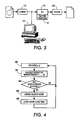
- FIG. 3 shows a general system requirement representing the goal of the invention.
- An electronic representation of a document (hereinafter, an image) from image input terminal such as scanner 10 is derived in a format related to the physical characteristics of the device, and commonly with pixels defined at m bits per pixel. Common color scanners have a pixel depth of 8 bits/separation pixel, at resolutions acceptable for many purposes.
- the image could be generated with appropriate image generation software at a computer or workstation 121. Since this is a color document, the image is defined with two or more separation bitmaps, usually with identical resolution and pixel depth.
- the electronic image signals are directed through an image processing unit (IPU) 16 to be processed so that an image suitable for reproduction on image output terminal or printer 20 is obtained.
- the IPU 16 could represent a software program in a general purpose digital computer.
- image processing unit 16 commonly includes a trapping processor 18 which corrects for traps formed at color edges.
- Figures 1A and 1B illustrate the problem of trapping.
- changes in colors occur exactly at a preplanned location, as shown in Figure 1A.
- misregistration common in real world devices using plural separations independently printed, often results in a visible image artifact or defect, as shown in Figure 1B. Such defects can be compensated with trapping.
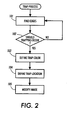
- Trapping usually takes place in accordance with the showing of Figure 2, in which, a) for any pair of colors (which may or may not correspond to an edge), a decision must be made b1) whether to trap; if so, b2) which color to use for the "trap color", (the color to interpose between the colors of the pair) and b3) where to place the chosen trap color.
- the decision to trap is based on the visibility of the worst artifact that could happen.
- the decision to trap is based on the visibility of the worst of all possible misregistration errors between the input colors.
- trap colors are chosen based on the visibility of the added trap color against each of the original colors, and based on the visibility of misregistration-induced colors against each of the original colors.
- trapping is a phenomenon of non-ideal printing devices. Trapping characteristics vary from printing technology to printing technology. In accordance with another aspect of the invention, information about the printing technology, or even regarding a particular printer, may be used to optimize the trapping process to be described.
- the trapping process takes the following form:
- a list (Misregister ( a,b )) is produced of all the unique colors that would appear between colors a and b , if a and b are misregistered in all possible ways.
- the assumption is that the worst case is that one or more of the separations is moved all the way from its nominal location to the edge of a specification, determined empirically by the printing process (See, Figures 1A and 1B).
- An alternative assumption would allow some separations to move only part way, thereby inducing more colors along the edge. We consider the case of one color along the edge.
- a function Misregister( a,b ) runs through all possible substitutions of a separation in a with a separation in b . There are, at most, 14 such substitutions. (Each of four separations is either substituted or not - but two cases, "all” or "none” substituted, do not require processing).
- Table 1 shows the colors that could appear on the left of an edge between the CMYK color (1,1,1,1) on the right with (0,0,0,0) on its left. Two of those colors are the original colors, leaving 14 possible new colors.
- LABvector is a signal or set of signals representing the possible misregistration colors in LAB space.
- LABvector is constructed from CMYKvector using device dependent color conversion, a process which entails a prior generation of samples of CMYKcolors, organized into a table, and mapped to LAB space, either directly or through an intermediate space. Before the first LABcolor is constructed, the necessary lookup tables are initialized as appropriate to the particular printer for which the colors are being converted.
- any color calibration system begins by measuring the LAB colors generated when a variety of CMYK colors are printed. These colors are interpolated to get the L AB color for the given CMYK color. Because the conversion is specific to the printer or type of printer, the visibility computed depends on the printer as well, as it should, since a particular amount of (C,M,Y,K) printed on one printer will not necessarily produce the same visual impression as the same amounts of colorants printed on a different printer.
- CIELAB space or a similar space CIELUV
- these spaces have a strong connection to visually perceptible color differences, which allow them to be used to determine, irrespective of the misregistration color, whether that color is likely to be visually perceptible.
- misregistered separations can result in color differences from the desired image, with the differences not plainly visible. Changes should only be made where the color differences due to misregistration are visible. Differences observed in CIELAB or CIELUV have a relationship to visibility in human color perception. This visibility is usable as a metric for how apparent a trap or trap modification can be.
- a visibilityvector (a,b) is constructed (step 258), and tested to see whether the max value of the vector is greater than a threshold- (step 260).
- the color difference formula is designed to give a value 1 at the limit of visibility, hence one good value of the threshold is 1.
- each of the input colors a and b is converted to an L*a*b* equivalent.
- a visibilityvector Given a CMYK color, we need to employ tetrahedral interpolation, or some other commonly known method of converting from device coordinates to device dependent color space. The process then loops through each of the elements (the possible misregistrations) of the LABvector, and computes the difference from a and from b for that element. It stores the minimum of these two differences. The minimum is the right one to store, because if c (the misregistration induced color) is less visible against a than against b, and c is between a and b, we might see c as part of a.
- a Visibilityvector is constructed from two colors (a, b) and the list of misregistration colors, and a list of values is built which correspond to the visibilities of all the misregistration colors. If the maximum entry in the Visibilityvector is less than a threshold value t ( Figure 4 and 5, step 204), the misregistration will not be visible. No action is taken at these two colors, and the next set of two colors is reviewed. However, if the maximum is greater than a threshold value t, the process continues to select a color for the trap (step 206). If the value of t is increased, fewer color pairs will be selected for trapping, and the process of checking for misregistration will proceed faster. However, image quality will be reduced. On the other hand, decreasing the value of t will result in more color pairs selected for trapping, and the process of checking will proceed slower. Generally image quality will be enhanced.
- the trapping color is selected or determined.
- a predetermined set of trapping colors is maintained as a palette, with selection throughout the gamut of a device (see “select a set of trapping colors CMYK(t)", step 300).
- User preferences can be used to generate the palette.
- every color T in the palette is compared to colors CMYK(a, b) (step 302) to see if T is between a, b (Step 304).
- Color T is not "between” if any of the values of C, M and Y for T are not between those for a and b (K may be ignored). Such colors not between a,b are discarded.
- a Trap_Visibilityvector AT is generated for a and T
- a Trap_Visibilityvector BT is generated for b and T. (Step 306).
- maximum visibility t m in AT and BT are determined (step 308). This gives the visibility of T against a or b, assuming the worst misregistration happens for one or the other of a and b. Of all the candidate colors T tried in the above loop, the one with the lowest maximum visibility T m is selected as representing the best trapping color candidate (Step 310).
- step 312 a check is performed to determine if the visibility of the candidate color is worse than the initial misregistration visibility found in step 258 of Figure 5 (step 312). If it is, no trapping is applied. Otherwise, however, the process proceeds to step 208, using the candidate color T whose worst visibility is the best of all the candidate colors tried. It has also been found that a good alternative to using the color with the least worst visibility, is taking the sum of the squares of the visibilities over all misregistrations and choosing the candidate with the smallest sum. In either case, the different visibilities might be weighted, given a priori knowledge of which misregistrations are more likely to occur.
- Trap_Visibilityvector is a class that behaves much like Visibilityvector. From two colors and a vector of misregistration colors a vector is built which correspond to the visibilities of all the misregistration colors. In the case of Trap_Visibilityvector the first color is the original color and the second color is the candidate trap color. The vector of misregistration doubles is one longer than the vector of misregistration colors. The visibilities are measured only between the original color and the misregistration colors, and between the original color and the candidate trap color, not between the candidate trap color and the misregistration colors. The use of this value is analogous to Visibilityvector, except that the second color is not compared against the misregistration colors, and the second color is compared against the first color
- the color of the trap has been selected, a decision must be made as to where to put it (step 208, Figure 4).
- trapping we interpose a new color between two colors that might misregister, thereby reducing or eliminating the visibility of any misregistration that should occur.
- This aspect of the invention relates to the location of the interposed color (trap). Specifically, the new color is put on one side of the original edge when the trap color is not very visible against the color on that side of the edge, and on the other side when it is not very visible against the color on the other side. When it is equally visible, the trap color is centered.
- the edge position By making the edge position a function of the difference between the two visibilities, we make the position smoothly vary from one side to the other when gradient fills abut. If the one color is in text, the position is not varied smoothly, but rather moved all the way over to one side or the other (whichever is less visible), to maintain the edge location of the text. Given the above, and with reference to Figure 7 and 8, the optimum place to put the trap color is on which ever side makes it less visible. Specifically, if trapping between color A and color B with trap color T, compute visibility by determining the Visibilityvector AT of T against A, and Visibilityvector BT of T against B (step 402). The vectors are initially converted to scalar values by taking a vector norm to drive bt and at.
- trap width w For trap width w, if A is to the left, move the center of the trap region to the left by (BT-AT)* k*w, for some value of k that depends on the particular model of visibility being used, subject to not moving it more than ⁇ w/2 (Step 402).
- Other functions relating the relative visibility of T against colors A, B may be used.
- Half-bitting allows the trap zone to move in increments of 1/2 of a pixel, so for a trap width of 2 pixels, this allows 5 positions. Thus, a smoothly varying trap position can be obtained.
- the visibility can be computed using S-CIELab-94, a spatially extended color difference metric, extended to use CIE94 color differencing, or from any other model of visibility that applies to thin lines against large background constant background regions.
- Vis ( A, T ) (( ⁇ L/S L ) 2 +( ⁇ C/S C ) 2 +( ⁇ H/S H )2 ) 1/2 where
- the added trap color will be placed side by side with the misregistration-caused colors.
- misregistration-induced colors there is little concern with the visibility of misregistration-induced colors against the trap color because this will be two very thin lines against each other, and it will be harder to see than one of the lines against a solid, which we assume the pair color to be.
- the required trapping is anamorphic (that is, its behavior in one dimension is different from that in another) in nature.
- a trap region required is twice as large in one direction, as in the other, because of the printing process direction.
- the trapping positional values can be scaled independently in each direction.
- all of the coordinates in the geometric description would be scaled by a factor (e.g. 2) in one dimension before trapping regions are calculated, and then all coordinates (including those of trapping regions) would be scaled down by the same factor, restoring the original geometry, but making trap regions that are thicker in one dimension than the other.
- an edge following process may be used with raster input, in which an edge following function is used.
- the standard practice is that the offset edge is displaced a constant distance along the vector normal (perpendicular) to the edge being followed.
- a coordinate transformation can be applied to the offset edge (in the example of trapping twice as wide in x, scale the normal by 2 in x). This will cause the offset edge to be displaced further from vertical edges than from horizontal edges, with a smooth variation in between.
- a windowing process might be used, or a morphological operator, with a window and its associated filters of morphological operator being appropriately scaled.
- FIG. 8 illustrates a system similar to the one shown in Figure 3, but better illustrating the possibility that IPU relies on a LUT storing trapping parameters.
- the goal with this method is to construct a table which, given colors A and B in CMYK space will produce a Boolean flag, and if the flag is true, a new color to be drawn between A and B. The flag will be false if the colors, when misregistered, will produce no visible artifact, e.g. (0,0,0,0) against anything; or there is no way of reducing the visibility of the artifact by interposing a third color.
- step 202 the visibility of potential misregistrations is checked.
- step 206 Choosing the color to insert between a and b, as in Figure 4, step 206:
- the first set of steps must be done for every pair of colors in color space.
- Half the color pairs are the mirror image of the other half, so it really only needs to be done for half of color space. If color space is quantized into n points, this is
- this table can be built off-line. In a table-based approach all that is done at run time is indexing the table. Table indexing is performed as follows:
- MAXINDEX is one less than a power of two, and the colors are supplied as tuples of integers, this can be optimized using shifts and masks.
- class VisibilityVector is a relatively complex process as described. It needs to convert its two given colors to a useful color space such as CIELAB, and also all the misregistered colors. It must also find the C* and H* coordinates for every color it converts.
- a secondary table may be easily formed, using data from the primary table, storing frequently or recently used color pair trapping information. Smaller tables are faster to check than the larger tables. A table would also provide an excellent location for storing user specified values for selected trapping situations. The position of the trap color between 2 colors can be put into the table as well.
- FIG 9 is a simplified illustration of the results of trapping.
- the trap zone between the cyan and red areas of the image, is characterized by having the trap color, selected to be between cyan and red.
- the trap color pixels on one side or the other of the ideal edge, in accordance with the process of Figure 7.
Applications Claiming Priority (2)
| Application Number | Priority Date | Filing Date | Title |
|---|---|---|---|
| US17727698A | 1998-10-22 | 1998-10-22 | |
| US177276 | 1998-10-22 |
Publications (2)
| Publication Number | Publication Date |
|---|---|
| EP0996281A2 true EP0996281A2 (de) | 2000-04-26 |
| EP0996281A3 EP0996281A3 (de) | 2001-03-21 |
Family
ID=22647951
Family Applications (1)
| Application Number | Title | Priority Date | Filing Date |
|---|---|---|---|
| EP99308187A Withdrawn EP0996281A3 (de) | 1998-10-22 | 1999-10-18 | Farbbildverarbeitungsverfahren und -system |
Country Status (2)
| Country | Link |
|---|---|
| EP (1) | EP0996281A3 (de) |
| JP (1) | JP2000165694A (de) |
Cited By (6)
| Publication number | Priority date | Publication date | Assignee | Title |
|---|---|---|---|---|
| US8164798B2 (en) | 2006-12-27 | 2012-04-24 | Dainippon Screen Mfg Co., Ltd. | Image processing apparatus and method for printing and plate making, and recording medium having image processing program recorded therein for printing and plate making |
| US8189242B2 (en) | 2005-09-01 | 2012-05-29 | Canon Kabushiki Kaisha | Apparatus and method for generating image data for forming a visible image |
| US8379266B2 (en) | 2008-09-30 | 2013-02-19 | Konica Minolta Laboratory U.S.A., Inc. | Systems and methods for generating luminance look-up table based on color component values |
| US8537425B2 (en) | 2008-09-30 | 2013-09-17 | Konica Minolta Laboratory U.S.A., Inc. | Method for optimizing the search for trapping regions |
| CN103575673A (zh) * | 2013-09-24 | 2014-02-12 | 岑夏凤 | 可测量色彩情感的分光光度计 |
| US9384427B2 (en) | 2008-12-16 | 2016-07-05 | Konica Minolta Laboratory U.S.A., Inc. | Systems and methods for optimizing pixel based raster trapping |
Families Citing this family (1)
| Publication number | Priority date | Publication date | Assignee | Title |
|---|---|---|---|---|
| US8199359B2 (en) * | 2006-04-28 | 2012-06-12 | Kyocera Mita Corporation | System and method for reducing visibility of registration errors in an image to be printed using a digital color printer by convolution with a laplacian kernel |
Citations (2)
| Publication number | Priority date | Publication date | Assignee | Title |
|---|---|---|---|---|
| EP0445066A2 (de) * | 1990-03-02 | 1991-09-04 | Scitex Corporation Ltd. | Verfahren zur Vorbereitung von polychromatischen Druckplatten |
| WO1995020796A1 (en) * | 1994-01-26 | 1995-08-03 | Adobe Systems Incorporated | Applying traps to a printed page specified in a page description language format |
-
1999
- 1999-10-15 JP JP11293124A patent/JP2000165694A/ja not_active Withdrawn
- 1999-10-18 EP EP99308187A patent/EP0996281A3/de not_active Withdrawn
Patent Citations (2)
| Publication number | Priority date | Publication date | Assignee | Title |
|---|---|---|---|---|
| EP0445066A2 (de) * | 1990-03-02 | 1991-09-04 | Scitex Corporation Ltd. | Verfahren zur Vorbereitung von polychromatischen Druckplatten |
| WO1995020796A1 (en) * | 1994-01-26 | 1995-08-03 | Adobe Systems Incorporated | Applying traps to a printed page specified in a page description language format |
Cited By (6)
| Publication number | Priority date | Publication date | Assignee | Title |
|---|---|---|---|---|
| US8189242B2 (en) | 2005-09-01 | 2012-05-29 | Canon Kabushiki Kaisha | Apparatus and method for generating image data for forming a visible image |
| US8164798B2 (en) | 2006-12-27 | 2012-04-24 | Dainippon Screen Mfg Co., Ltd. | Image processing apparatus and method for printing and plate making, and recording medium having image processing program recorded therein for printing and plate making |
| US8379266B2 (en) | 2008-09-30 | 2013-02-19 | Konica Minolta Laboratory U.S.A., Inc. | Systems and methods for generating luminance look-up table based on color component values |
| US8537425B2 (en) | 2008-09-30 | 2013-09-17 | Konica Minolta Laboratory U.S.A., Inc. | Method for optimizing the search for trapping regions |
| US9384427B2 (en) | 2008-12-16 | 2016-07-05 | Konica Minolta Laboratory U.S.A., Inc. | Systems and methods for optimizing pixel based raster trapping |
| CN103575673A (zh) * | 2013-09-24 | 2014-02-12 | 岑夏凤 | 可测量色彩情感的分光光度计 |
Also Published As
| Publication number | Publication date |
|---|---|
| EP0996281A3 (de) | 2001-03-21 |
| JP2000165694A (ja) | 2000-06-16 |
Similar Documents
| Publication | Publication Date | Title |
|---|---|---|
| EP0996282B1 (de) | Drucksystem und -verfahren | |
| EP0998131A2 (de) | Farbdrucksystem und -verfahren | |
| US6781720B1 (en) | Gradient-based trapping using patterned trap zones | |
| EP0550243B1 (de) | Farbbildverarbeitung | |
| US6441923B1 (en) | Dynamic creation of color test patterns based on variable print settings for improved color calibration | |
| EP1014694B1 (de) | Automatische Verbesserung der Druckqualität basiert auf Grösse, Form, Orientierung und Farbe von Strukturen | |
| EP0720351B1 (de) | Verfahren zur Erzeugung von Farbprobeabzügen | |
| US6381037B1 (en) | Dynamic creation of color test patterns for improved color calibration | |
| EP0772347B1 (de) | Farbdrucker mit Zittermuster | |
| US5740076A (en) | System for describing a color gamut in a graphical data processing system | |
| US6657746B1 (en) | Look-up table constructing method and color conversion apparatus | |
| US5463471A (en) | Method and system of color halftone reproduction | |
| EP1814309A1 (de) | Bildverarbeitungsgerät und Bildverarbeitungsverfahren | |
| US20110317222A1 (en) | Methods and apparatus for dynamically soft proofing halftone images | |
| US7576893B2 (en) | Correlated secondary TRC calibration method | |
| JP4044667B2 (ja) | クロミナンス変調による擬似輪郭の削減方法及びシステム | |
| EP0996281A2 (de) | Farbbildverarbeitungsverfahren und -system | |
| EP1202559B1 (de) | Farbe zu Schwarzweiss Konverter | |
| US6771390B1 (en) | Method for modifying the size of line elements | |
| US6891641B1 (en) | Method and apparatus for converting number of colors and processing image data | |
| KR100731582B1 (ko) | 6색 프린터 시스템 및 그 6색 분리 방법 | |
| KR100284685B1 (ko) | 균등 색공간에서 프린터 모델을 위한 칼라 하프톤닝방법 및 회로 | |
| US8462389B2 (en) | Halftone-independent scanner profiling |
Legal Events
| Date | Code | Title | Description |
|---|---|---|---|
| PUAI | Public reference made under article 153(3) epc to a published international application that has entered the european phase |
Free format text: ORIGINAL CODE: 0009012 |
|
| AK | Designated contracting states |
Kind code of ref document: A2 Designated state(s): AT BE CH CY DE DK ES FI FR GB GR IE IT LI LU MC NL PT SE |
|
| AX | Request for extension of the european patent |
Free format text: AL;LT;LV;MK;RO;SI |
|
| PUAL | Search report despatched |
Free format text: ORIGINAL CODE: 0009013 |
|
| AK | Designated contracting states |
Kind code of ref document: A3 Designated state(s): AT BE CH CY DE DK ES FI FR GB GR IE IT LI LU MC NL PT SE |
|
| AX | Request for extension of the european patent |
Free format text: AL;LT;LV;MK;RO;SI |
|
| STAA | Information on the status of an ep patent application or granted ep patent |
Free format text: STATUS: THE APPLICATION HAS BEEN WITHDRAWN |
|
| 18W | Application withdrawn |
Withdrawal date: 20010914 |