EP0996099A2 - Electroluminescent semiconductor for testing luminescent security features - Google Patents
Electroluminescent semiconductor for testing luminescent security features Download PDFInfo
- Publication number
- EP0996099A2 EP0996099A2 EP99120299A EP99120299A EP0996099A2 EP 0996099 A2 EP0996099 A2 EP 0996099A2 EP 99120299 A EP99120299 A EP 99120299A EP 99120299 A EP99120299 A EP 99120299A EP 0996099 A2 EP0996099 A2 EP 0996099A2
- Authority
- EP
- European Patent Office
- Prior art keywords
- radiation
- solid
- electroluminescent
- security features
- wavelength range
- Prior art date
- Legal status (The legal status is an assumption and is not a legal conclusion. Google has not performed a legal analysis and makes no representation as to the accuracy of the status listed.)
- Granted
Links
- 239000004065 semiconductor Substances 0.000 title claims description 18
- 238000012360 testing method Methods 0.000 title description 17
- 230000005855 radiation Effects 0.000 claims abstract description 41
- 238000000034 method Methods 0.000 claims abstract description 20
- 239000007787 solid Substances 0.000 claims abstract 10
- 230000003287 optical effect Effects 0.000 claims description 7
- 239000002131 composite material Substances 0.000 claims description 2
- 238000001514 detection method Methods 0.000 claims description 2
- 238000005265 energy consumption Methods 0.000 claims description 2
- 230000005284 excitation Effects 0.000 claims description 2
- 210000001525 retina Anatomy 0.000 claims description 2
- 238000012544 monitoring process Methods 0.000 abstract 1
- 239000003086 colorant Substances 0.000 description 11
- 230000008901 benefit Effects 0.000 description 8
- 239000000463 material Substances 0.000 description 7
- 230000008859 change Effects 0.000 description 5
- 238000013461 design Methods 0.000 description 5
- 230000000694 effects Effects 0.000 description 5
- 238000012795 verification Methods 0.000 description 5
- 238000006243 chemical reaction Methods 0.000 description 4
- 230000001419 dependent effect Effects 0.000 description 3
- 238000005516 engineering process Methods 0.000 description 3
- 238000004020 luminiscence type Methods 0.000 description 3
- 230000003595 spectral effect Effects 0.000 description 3
- PPBRXRYQALVLMV-UHFFFAOYSA-N Styrene Chemical compound C=CC1=CC=CC=C1 PPBRXRYQALVLMV-UHFFFAOYSA-N 0.000 description 2
- 230000004888 barrier function Effects 0.000 description 2
- 238000011161 development Methods 0.000 description 2
- 238000004519 manufacturing process Methods 0.000 description 2
- 239000000203 mixture Substances 0.000 description 2
- 230000008569 process Effects 0.000 description 2
- 230000011514 reflex Effects 0.000 description 2
- 238000001228 spectrum Methods 0.000 description 2
- 238000012546 transfer Methods 0.000 description 2
- NLHHRLWOUZZQLW-UHFFFAOYSA-N Acrylonitrile Chemical compound C=CC#N NLHHRLWOUZZQLW-UHFFFAOYSA-N 0.000 description 1
- 240000001913 Atriplex hortensis Species 0.000 description 1
- 208000020564 Eye injury Diseases 0.000 description 1
- 239000004904 UV filter Substances 0.000 description 1
- 230000006378 damage Effects 0.000 description 1
- 230000003247 decreasing effect Effects 0.000 description 1
- 230000003203 everyday effect Effects 0.000 description 1
- 230000036541 health Effects 0.000 description 1
- 238000005286 illumination Methods 0.000 description 1
- 238000001746 injection moulding Methods 0.000 description 1
- 238000009434 installation Methods 0.000 description 1
- 210000003205 muscle Anatomy 0.000 description 1
- 210000001328 optic nerve Anatomy 0.000 description 1
- 238000003825 pressing Methods 0.000 description 1
- 230000000717 retained effect Effects 0.000 description 1
- 239000000243 solution Substances 0.000 description 1
- 239000004575 stone Substances 0.000 description 1
- 238000003860 storage Methods 0.000 description 1
- 238000010998 test method Methods 0.000 description 1
- 229920001169 thermoplastic Polymers 0.000 description 1
- 239000004416 thermosoftening plastic Substances 0.000 description 1
- 230000001960 triggered effect Effects 0.000 description 1
- 238000012800 visualization Methods 0.000 description 1
- XLYOFNOQVPJJNP-UHFFFAOYSA-N water Substances O XLYOFNOQVPJJNP-UHFFFAOYSA-N 0.000 description 1
Images


Classifications
-
- G—PHYSICS
- G07—CHECKING-DEVICES
- G07D—HANDLING OF COINS OR VALUABLE PAPERS, e.g. TESTING, SORTING BY DENOMINATIONS, COUNTING, DISPENSING, CHANGING OR DEPOSITING
- G07D7/00—Testing specially adapted to determine the identity or genuineness of valuable papers or for segregating those which are unacceptable, e.g. banknotes that are alien to a currency
- G07D7/06—Testing specially adapted to determine the identity or genuineness of valuable papers or for segregating those which are unacceptable, e.g. banknotes that are alien to a currency using wave or particle radiation
- G07D7/12—Visible light, infrared or ultraviolet radiation
- G07D7/1205—Testing spectral properties
Definitions
- the present invention relates to a method and an apparatus for Verification of luminescent security features using UV and Luminescent diodes (LEDs) emitting infrared light.
- LEDs UV and Luminescent diodes
- Luminescent security features for the value and security area have been used for a long time. To the security features on the affected security and valuables are attached with Reliable efforts to make acceptable efforts visible have already been varied Efforts have been made to implement appropriate procedures and devices to develop.
- luminescent security features are not yet visible matured to the extent that it is easy and uncomplicated to use enable reliable detection of the security features.
- the present invention is therefore based on the object of a method and a device for the verification of luminescent Security features, which in and / orr on value and Security documents and objects are arranged, the Application of the device and control of the concerned Security features simple, uncomplicated, repeatable at any time, without health damage to the user and those in the immediate Surrounding people is feasible, and the control procedure with the control device without line-dependent energy and Information transfer should be executable.
- luminescent material with imperceptible afterglow which is called fluorescent
- the second type of luminescent material, which has the effect of a Afterglow is called phosphorizing.
- the energy supply for the operation of the LEDs used can due to the low power consumption compared to the tubes, definitely via batteries, so-called button cells. Through this Power supply, it is guaranteed that the test equipment for Verification of luminescent security elements regardless of location can be done. Another advantage is that the test facility can be transported easily and based on the small dimensions and associated light weight available to everyone at all times can stand by this testing facility, like other everyday utensils Is always at hand.
- diodes in one Composite are arranged so that they form a bundle which roughly approximately the same beam direction its at least partially outside the radiate visible radiation in the visible wavelength range.
- an essential safety feature of the present Invention is at least one among this bundle of light emitting diodes Light-emitting diode arranged, which emits light in the visible range, whereby a first security feature, namely an optical operating display, Is used.
- a first security feature namely an optical operating display
- Another additional safety device from The present invention is that optionally an additional acoustic operating display of those working in the invisible spectral range LEDs indicate.
- Another advantage of the present invention over those previously Fluorescent lamps used is that the life of the LEDs are a multiple of the life of fluorescent lamps. Especially when the fluorescent lamps are switched on and off frequently Lifespan of this is significantly reduced, creating an average Lifespan of approximately 1000 operating hours for the fluorescent lamps is far below. The lifespan of the LEDs, however, is one Multiples of 1000 operating hours.
- UV-LED's UV light-emitting diodes
- the UV LEDs are in their design and in their electrical characteristics comparable to conventional light emitting diodes. LEDs for the visible wavelength range (wavelength 400 nanometers to 700 nanometers) and for the near infrared range (IR; wavelength 700 Nanometers to 1000 nanometers) have been in use for a long time. You will be in the technology above all as display elements (blue, green, yellow and red LEDs) or used in remote controls, light barriers (IR LEDs). The Desire for ever shorter wavy LEDs is justified by the fact that the optical storage density of data, for example on CD or DVD decreasing wavelength is getting bigger.
- LEDs work in a wavelength range of 370 nanometers and thus have a wavelength similar to that of commercially available UV lamps (Wavelength 375 nanometers).
- Another advantage of the light emitting diodes over the fluorescent tubes is in that the light emitting diodes immediately provide their full optical power as soon as they are energized.
- the fluorescent tube however, it takes a certain amount of time to ignite the gas and thus to achieve their luminosity and operational readiness.
- In order to the disadvantage of the waiting time between are automatically connected Switch-on time and the first operational state of the fluorescent tube as well as the disadvantage of the significantly higher power consumption.
- a power supply is required for the correct operation of these LEDs between 3.5 volts and 4.5 volts necessary.
- This power supply can using appropriately sized batteries for a satisfactorily long time Service life can be achieved.
- a consistently intense luminosity can be achieved by using a Constant current source for the supply of the UV LEDs can be achieved. Care the transistors used to ensure that the UV LEDs are always the same Voltage drops, which results in constant luminosity when in use. By using such a constant current source, it is also possible Use battery voltages above 4.5 volts, which are caused by the electronics the correspondingly required values are limited. With the previously specified Data thus generates a power consumption of approximately 10 milliamperes. Under These operating conditions have a lifespan of approximately 2000 Operating hours according to the manufacturer's specification. When using conventional alkaline batteries of the type LR44 (1.5 volts) result in a Operating time of approximately 12 hours. Set one for reviewing one Security and value document for a period of 10 seconds a number of test operations, which is 4320 operations.
- the present invention provides that the suggestion for delivery luminescent radiation caused by the infrared or ultraviolet Radiation, by pulse method for the operating voltage supplied used LED's is influenced so that different colors the correspondingly excited luminescence security features on the value and Sign off security documents and objects. Background this changing color spectrum of the luminescent features emitted radiation is the superposition of emitted luminescent Radiation from different frequency ranges due to use of different colors, the individual decay constants of different Order of magnitude. It is advantageous to use luminescent colors which have significantly different decay constants.
- the ultraviolet or infrared radiation which is released from the semiconductor solid-state elements, is therefore directly from dependent on the voltage, since this immediately gives its full radiation power when applied of a corresponding voltage and this until the switch-off time maintained.
- the luminescent security features in the Form of the supplied operating voltage from the infrared and ultraviolet Radiation irradiated. Due to the intermittent and / or modulated form of this Power supply are now the retroreflective characteristics of the for Security features used luminescent colors depending on their Decay constants recorded by the eye.
- the color A is green and the color B is blue pulsed power supply the reflection of the security elements the Color blue / green.
- the voltage supply will change over time in the cycle the color A - i.e. green - always between the voltage switched on and off weaker and the color blue would remain constant. This modulation can go so far be driven until the reflection of the color green has completely subsided is. In this case the color would now be blue, based on its large size Decay constant, still emit visible radiation.
- the present invention now provides that the modulation method for Operating voltage of the LED's are optional when checking the value and Security documents and objects vary. This allows the whole Frequency spectrum of the applied security features can be checked. This is shown by a change in the retroreflective colors, which change results from the sum of the retroreflective frequencies.
- Another alternative power supply results from the use of a DC / DC inverter.
- This IC is able to measure the voltage of a battery multiply. In this way it is possible to add electronics for the UV LEDs develop that only needs one or two LR44 batteries.
- This embodiment is an alternative to the embodiment with the Constant current source.
- the core housing is made of acrylonitrile butodiene styrene copylymere (ABS) in the thermoplastic injection molding process.
- ABS acrylonitrile butodiene styrene copylymere
- elastomeric elements are used so that the function of the test facility through Floor traps from hip or shoulder height, even on hard floors, such as Stone floors or the like, is not affected.
- the high breaking strength of the test facility achieved in this way is another Security feature of the present invention.
- Another feature of Safe operation of the test equipment lies in the fact that the housing design is designed such that it is closed to protect against splashing water.
- the UV LEDs are arranged in the housing in such a way that they are scratched by protruding elements is avoided and so the opening angle of approximately 10 ° of the emitting UV and / or IR light is retained at all times.
- This stationary UV LED lamp comes with several LEDs are equipped to provide a uniform, intensive illumination guarantee.
- This verifier can optionally be equipped with a UV filter his. This filter can remove the annoying, visible, blue light components of the UV LEDs reduce and thus an improved visibility of the luminescence enable. In addition, the color fastness of the luminescence compared to that restored with UV lamp.
- a proximity sensor In order to enable a corresponding value and security product or object to be recognized when it is brought into the control position, it is provided to install a proximity sensor.
- This proximity sensor switches on the power supply for the LEDs when a value and security product or object is detected. This enables the control process described above to be triggered.
- the UV-LED verifier is therefore equipped with a sensor that detects whether a security document to be checked is under the device.
- the UV LEDs are only switched on in this case.
- Such a sensor could be implemented using a simple light barrier.
- the advantage of this solution is that the UV LEDs are only switched on when they are needed.
- the service life is significantly increased in this operation and exceeds that of a stationary UV lamp, with which such operation is not possible, many times over.
- UV LEDs In addition to those under UV light luminescent Security features are also increasingly used feature materials that under irradiation with infrared light in the visible lighting area (down-conversion or anti-stocks) converge. A combination of UV and IR LEDs is therefore sensible, since it checks both security features in this way can be.
- FIG. 1 shows a UV-IR-LED pointer, which has 5 UV-LEDs in a housing 2, IR LEDs 3, LEDs in the visible wave range 4, and batteries 6 includes.
- the button 9 On the electronics 6 energy on the LEDs 2,3,4 voltage in the intended operating voltage level delivered and this stimulated to glow.
- the acoustic display 12 for emitting a signal by actuating with the appropriate spring force provided button 9 causes. Through this acoustic signal, as well the LED in the visible wave range ensures that none invisible radiation can escape from the LED's without warning signals be delivered in both optical and acoustic form.
- the levy The optical signal is used to trigger the closing reflex of the eye muscles.
- the emission of the ultraviolet or infrared radiation from the UV / IR LEDs serves to stimulate the luminescent security features of the checking value and security documents and objects. Due to the Excitation by ultraviolet or infrared light is given to the Security features a down-conversion energy transfer takes place which the safety features for radiation in the visible wavelength range stimulates.
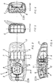
- Figure 2 shows a plan view of the embodiment of Figure 1, the Top view is from the direction in which the emitted radiation from the LED's is directed. With this arrangement, several LEDs can be seen, which in one bundled state on the front side of the housing 5 of the UV-IR LED pointer are arranged.
- FIG. 3 shows a sectional view of a further embodiment of the Present invention, the LED combination UV-LED 2, IR-LED 3 and LEDs in the visible wave range 4 are shown as a single unit. Furthermore, the electronics 8 are the buttons 9 and the batteries 6 with the contacts 7 recognizable in the housing 5. The operation of this embodiment corresponds in principle the mode of operation of the previously described embodiment.
- FIG. 4 shows a vertical sectional view according to FIG. 3.
- the ergonomic design of the handy UV / IR LED pointer is clear in form recognizable.
- At the bottom of the case is an ergonomic one Grip recess 10 recognizable.
- FIG. 5 shows a sectional view through section A-A of FIG. 3.
- the arrangement of four batteries 6 in the housing 5 shown. These batteries are used to supply power to the UV LEDs IR-LED's, as well as the LED in the visible wave range and the acoustic Operating display 12.
- Figure 6 shows a sectional view according to section B-B of Figure 3.
- Housing 5 on the left side of the recessed grip 10 can be seen, which also in the Figure 4 is shown in the lower left area.
- Button 9 and the LED unit 2,3,4 shown for the LEDs.
- the electronics 8 are still parts of the electronics 8 recognizable
- FIG. 9 shows a front view of this inner part of this embodiment of the present invention.
- the button 9 is located behind it and an electronic component 8.
- the contacts 7 recognizable with their connections to the board.
Abstract
Description
Die vorliegende Erfindung betrifft ein Verfahren und eine Vorrichtung zur Verifikation von lumineszierenden Sicherheitsmerkmalen anhand UV- und Infrarot-Licht abstrahlenden Lumineszenzdioden (LED's).The present invention relates to a method and an apparatus for Verification of luminescent security features using UV and Luminescent diodes (LEDs) emitting infrared light.
Lumineszierende Sicherheitsmerkmale für den Wert- und Sicherheitsbereich werden bereits seit längerer Zeit eingesetzt. Um die Sicherheitsmerkmale, die auf den betroffenen Sicherheits- und Wertgegenständen angebracht sind, mit akzeptablem Aufwand zuverlässig sichtbar zu machen, wurden bereits vielfältige Anstrengungen unternommen, um entsprechende Verfahren und Vorrichtungen zu entwickeln.Luminescent security features for the value and security area have been used for a long time. To the security features on the affected security and valuables are attached with Reliable efforts to make acceptable efforts visible have already been varied Efforts have been made to implement appropriate procedures and devices to develop.
Als Zielsetzung wurde in den meisten Fällen die Überprüfung von Banknoten, Kredit- bzw. Scheckkarten an Verkaufsstellen für die Entwicklung entsprechender Verfahren und Vorrichtungen vorgegeben. Als Verkaufsräume oder Verkaufsstellen werden dabei alle erdenklichen Orte angesehen, an denen Wert- oder Sicherheitsdokumente, wie z.B. Geldscheine, Kredit- und Scheckkarten sowie Ausweispapiere und dergleichen vertrieben, gehandelt, gewechselt und kontrolliert werden. Um einen zuverlässigen Nachweis der Echtheit der betroffenen Wert- und Sicherheitsdokumente dem betreffenden Personenkreis zur Verfügung zu stellen, wurden besagte Anstrengungen unternommen, um Verfahren und Vorrichtungen zur Sichtbarmachung dieser lumineszierenden Sicherheitselemente zu erzielen.In most cases, the objective was to check banknotes, Credit or check cards at sales outlets for the development of corresponding ones Methods and devices specified. As salesrooms or Sales outlets are looked at all conceivable places where value or Security documents, such as Banknotes, credit and bank cards as well as identity papers and the like sold, traded, changed and to be controlled. To provide reliable evidence of the authenticity of the affected value and security documents to the relevant group of people Efforts have been made to provide Methods and devices for making these luminescent visible To achieve security elements.
Die bisher bekannten und vorliegenden Verfahren und Vorrichtungen zur Sichtbarmachung lumineszierender Sicherheitsmerkmale sind jedoch noch nicht so weit ausgereift, daß sie eine einfache und unkomplizierte Handhabung mit zuverlässiger Erkennung der Sicherheitsmerkmale ermöglichen.The previously known and available methods and devices for However, luminescent security features are not yet visible matured to the extent that it is easy and uncomplicated to use enable reliable detection of the security features.
Der vorliegenden Erfindung liegt deshalb die Aufgabe zugrunde, ein Verfahren und eine Vorrichtung zur Verfikikation von lumineszierenden Sicherheitsmerkmalen, welche in und/oderr auf Wert- und Sicherheitsdokumenten- und Gegenständen angeordnet sind, wobei die Anwendung der Vorrichtung und die Kontrolle der betreffenden Sicherheitsmerkmale einfach, unkompliziert, jederzeit wiederholbar, ohne gesundheitliche Schädigung für den Anwender und die in der unmittelbaren Umgebung befindlichen Personen durchführbar ist, und das Kontrollverfahren mit der Kontrolleinrichtung ohne leitungsabhängige Energie- und Informationsübermittlung ausführbar sein soll.The present invention is therefore based on the object of a method and a device for the verification of luminescent Security features, which in and / orr on value and Security documents and objects are arranged, the Application of the device and control of the concerned Security features simple, uncomplicated, repeatable at any time, without health damage to the user and those in the immediate Surrounding people is feasible, and the control procedure with the control device without line-dependent energy and Information transfer should be executable.
Zur Lösung der gestellten Aufgabe dienen die kennzeichnenden Merkmale der
unabhängigen Ansprüche 1 und 8.The characteristic features of
Wichtig für die vorliegende Erfindung ist, daß für die Verifikation der betreffenden Sicherheitsmerkmale, welche in und/oder auf Wert- und Sicherheitsdokumenten und -Gegenständen angeordnet sind, um deren Echtheit bei Prüfung mittels eines geeigneten Prüfungsverfahrens mit einer entsprechenden Prüfvorrichtung nachzuweisen, das Verfahren einfach handhabbar ist, wobei zur Sichtbarmachung der Sicherheitsmerkmale sowohl Strahlung im ultravioletten Wellenlängenbereich als auch im infraroten Wellenlängenbereich unter Ausnutzung des Down-Conversion-Effektes eingesetzt wird. Unter Down-Conversion wird folgender Effekt verstanden, daß speziell dotiertes, lumineszierendes Material durch Strahlung, welche im nicht-sichtbaren Bereich erfolgt, angeregt wird, und entsprechend der Dotierung des lumineszierenden Materials einen Sprung auf dem Energieband erfährt, und im sichtbaren Spektralbereich nach der Konvergierung des Energiezustandes Strahlung aussendet. Diese Strahlung kann durch das menschliche Auge erfasst werden, wodurch sich der Nachweis des Vorhandenseins von Sicherheitsmerkmalen auf zu prüfenden Sicherheits- und Wertdokumenten und -Gegenständen erbringen lässt.It is important for the present invention that for the verification of the concerned Security features that are in and / or on value and security documents and objects are arranged to ensure their authenticity when checked by means of a suitable test procedure with a corresponding test device to demonstrate that the process is easy to use, with the Visualization of security features both radiation in the ultraviolet Wavelength range as well as in the infrared wavelength range Exploitation of the down conversion effect is used. Under down conversion the following effect is understood that specially doped, luminescent material by radiation, which is in the non-visible area takes place, is excited, and according to the doping of the luminescent Materials experiences a jump on the energy band, and in the visible Spectral range after the convergence of the energy state radiation sends out. This radiation can be detected by the human eye whereby the evidence of the presence of security features is based on provide security and value documents and objects to be checked leaves.
Bei der Erzeugung eines lumineszierenden Effektes finden zwei unterschiedliche Materialien Anwendung. Zum einen handelt es sich um lumineszierendes Material mit nicht-wahrnehmbaren Nachleuchten, welches als fluoreszierend bezeichnet wird, und die zweite Art von lumineszierendem Material, welche den Effekt eines Nachleuchtens bewirkt, wird als phosphorisierend bezeichnet.There are two different ways to create a luminescent effect Materials application. First, it is luminescent material with imperceptible afterglow, which is called fluorescent and the second type of luminescent material, which has the effect of a Afterglow is called phosphorizing.
Für die Verwendung von Sicherheitsmerkmalen in Sicherheits- und Wertdokumenten und -Gegenständen spielt es jedoch keine Rolle, welches der beiden lumineszierenden Materialien verwendet wird. Entscheidend ist nur der Nachweis des Vorhandenseins von Sicherheitsmerkmalen.For the use of security features in security and However, value documents and objects do not matter which of the two luminescent materials is used. Only that is decisive Evidence of the presence of security features.
Zur Anregung der lumineszierenden Sicherheitsmerkmale ist es notwendig, UV-Licht auf die lumineszierenden Sicherheitsmerkmale zu richten, was bisher durch den Einsatz von unhandlichen Leuchtstoffröhren erfolgte. Diese Leuchtstoffröhren waren aufgrund der hohen Leistung leitungsgebunden und wiesen ebenfalls unhandliche Abmasse auf, welche einen einfachen und handlichen Einsatz nicht zuliessen. Wichtig bei der vorliegenden Erfindung ist nun, daß durch den Einsatz im UV-Bereich arbeitenden Lumineszenz-Dioden die Möglichkeit besteht, eine Prüfeinrichtung zu bauen, welche in einer sehr handlichen Ausführung mit kleinen Abmassen, z.B. in der Form eines Schlüsselanhängers, gefertigt werden können. Daraus ergibt sich erstmals die Möglichkeit, eine Prüfeinrichtung leitungsungebunden und leicht transportierbar und einsetzbar zu fertigen.To stimulate the luminescent security features, it is necessary to use UV light to focus on the luminescent security features, what so far bulky fluorescent tubes were used. These fluorescent tubes were wired due to the high performance and also showed unwieldy dimensions, which are not easy and handy to use allow. It is important in the present invention that through the use Luminescent diodes working in the UV range have the possibility of a To build test facility, which in a very handy design with small Dimensions, e.g. in the form of a keychain. This gives the first time the possibility of a test facility cable-free and easy to transport and use.
Die Energieversorgung für den Betrieb der eingesetzten Leuchtdioden kann aufgrund des geringen Stromverbrauchs, verglichen mit den Röhren, durchaus über Batterien, sogenannte Knopfzellen, erfolgen. Durch diese Spannungsversorgung ist es gewährleistet, daß die Prüfeinrichtung zur Verifizierung von lumineszierenden Sicherheitselementen ortsunabhängig erfolgen kann. Als weiterer Vorteil ist hervorzuheben, daß die Prüfeinrichtung problemlos transportiert werden kann und anhand der geringen Abmasse und des damit verbundenen geringen Gewichts für jedermann jederzeit zur Verfügung stehen kann, indem diese Prüfeinrichtung, wie andere Utensilien des täglichen Bedarfs, ständig griffbereit ist.The energy supply for the operation of the LEDs used can due to the low power consumption compared to the tubes, definitely via batteries, so-called button cells. Through this Power supply, it is guaranteed that the test equipment for Verification of luminescent security elements regardless of location can be done. Another advantage is that the test facility can be transported easily and based on the small dimensions and associated light weight available to everyone at all times can stand by this testing facility, like other everyday utensils Is always at hand.
Wichtig bei der vorliegenden Erfindung ist, daß mehrere Dioden in einem Verbund so angeordnet sind, daß sie ein Bündel bilden welches in eine etwa annähernd gleiche Strahlrichtung ihre wenigstens zum Teil außerhalb des sichtbaren Wellenlängenbereichs liegende Strahlung abstrahlen. Der Einsatz mehrerer Leuchtdioden zum Zwecke der Aussendung von Strahlung, welche wenigstens zum Teil, außerhalb des sichtbaren Spektralbereichs liegen, liegt darin, daß durch die Bündelung der Aussendung von Strahlen eine höhere Leuchtdichte erreicht wird, welche eine intensivere Sichtbarmachung der lumineszierenden Sicherheitsmerkmale ermöglicht. It is important in the present invention that several diodes in one Composite are arranged so that they form a bundle which roughly approximately the same beam direction its at least partially outside the radiate visible radiation in the visible wavelength range. The stake several light emitting diodes for the purpose of emitting radiation, which are at least partially outside the visible spectral range in that by bundling the emission of rays a higher one Luminance is achieved, which makes the allows luminescent security features.
Als weiteres wesentliches sicherheittechnisches Merkmal der vorliegenden Erfindung ist unter diesem Bündel von Leuchtdioden wenigstens eine Leuchtdiode angeordnet, welche Licht im sichtbaren Bereich ausstrahlt, wodurch ein erstes Sicherheitsmerkmal, nämlich eine optische Betriebsanzeige, Verwendung findet. Eine weitere, zusätzliche Sicherheitseinrichtung der vorliegenden Erfindung besteht darin, daß wahlweise auch zusätzlich eine akustische Betriebsanzeige der, im nicht-sichtbaren Spektralbereich arbeitenden, Leuchtdioden anzeigt. Durch die Einbringung dieser sicherheitstechnischen Merkmale wird vermieden, daß beabsichtigt oder auch unbeabsichtigt, Augenverletzungen durch Verbrennen der Sehnerven auf der Netzhaut, hervorgerufen durch nicht wahrgenommene Strahlung und dadurch das Nichtauslösen des Fließreflexes des Auges, vermieden wird.As another essential safety feature of the present Invention is at least one among this bundle of light emitting diodes Light-emitting diode arranged, which emits light in the visible range, whereby a first security feature, namely an optical operating display, Is used. Another additional safety device from The present invention is that optionally an additional acoustic operating display of those working in the invisible spectral range LEDs indicate. By introducing these safety-related Features is avoided that intentional or unintentional Eye injuries from burning the optic nerves on the retina, caused by unperceived radiation and thereby the Not triggering the flow reflex of the eye, is avoided.
Ein weiterer Vorteil der vorliegenden Erfindung gegenüber den bisher eingesetzten Leuchtstofflampen liegt darin, daß die Lebensdauer der Leuchtdioden ein Vielfaches der Lebensdauer der Leuchtstofflampen beträgt. Speziell bei häufigem Ein- und Ausschalten der Leuchtstofflampen wird die Lebensdauer dieser deutlich herabgesetzt, wodurch eine durchschnittliche Lebensdauer von ungefähr 1000 Betriebsstunden für die Leuchtstofflampen bei weitem unterschritten wird. Die Lebensdauer der LED's liegt dagegen bei einem Vielfachen von 1000 Betriebsstunden.Another advantage of the present invention over those previously Fluorescent lamps used is that the life of the LEDs are a multiple of the life of fluorescent lamps. Especially when the fluorescent lamps are switched on and off frequently Lifespan of this is significantly reduced, creating an average Lifespan of approximately 1000 operating hours for the fluorescent lamps is far below. The lifespan of the LEDs, however, is one Multiples of 1000 operating hours.
Daraus ergeben sich die Vorteile, daß bei der vorliegenden Erfindung eine leitungsunabhängige, jederzeit und überall einsetzbare, mit hoher Lebensdauer ausgestattete, Prüfeinrichtung gefertigt werden kann.This results in the advantages that in the present invention Cable-independent, can be used anytime and anywhere, with a long service life equipped, test facility can be manufactured.
So wird durch die Realisierung dieses völlig neuartigen Konzeptes, welches den Einsatz der UV-Leuchtdioden (UV-LED's) vorsieht, diese hohe Flexibilität für den Anwendungsfall erreicht. Dabei sind die UV-Leuchtdioden in ihrer Bauform und in ihren elektrischen Charakteristikas mit herkömmlichen Leuchtdioden vergleichbar. Leuchtdioden für den sichtbaren Wellenbereich (Wellenlänge 400 Nanometer bis 700 Nanometer) und für den nahen Infrarotbereich (IR; Wellenlänge 700 Nanometer bis 1000 Nanometer) sind schon lange gebräuchlich. Sie werden in der Technik vor allen Dingen als Anzeige-Elemente (blaue, grüne, gelbe und rote LED's) oder in Fernbedienungen, Lichtschranken (IR-LED's) eingesetzt. Der Wunsch nach immer kürzer welligen Leuchtdioden wird dadurch begründet, daß die optische Speicherdichte von Daten, auf beispielsweise CD oder DVD, mit abnehmender Wellenlänge immer größer wird.The realization of this completely new concept, which Use of UV light-emitting diodes (UV-LED's) provides this high flexibility for the Use case reached. The UV LEDs are in their design and in their electrical characteristics comparable to conventional light emitting diodes. LEDs for the visible wavelength range (wavelength 400 nanometers to 700 nanometers) and for the near infrared range (IR; wavelength 700 Nanometers to 1000 nanometers) have been in use for a long time. You will be in the technology above all as display elements (blue, green, yellow and red LEDs) or used in remote controls, light barriers (IR LEDs). The Desire for ever shorter wavy LEDs is justified by the fact that the optical storage density of data, for example on CD or DVD decreasing wavelength is getting bigger.
Lange Zeit war es nicht möglich, kurzwellige, blaue Leuchtdioden herzustellen, da keine geeignete Technologie für die Serienproduktion zur Verfügung stand. Erst seit ungefähr 5 Jahren gibt es von der Firma Nichia entsprechende Leuchtdioden, die diese technologische Lücke mit der Fertigung von Serienprodukten zur Erzeugung von blauen Leucht- bzw. Laserdioden schließt. Durch eine Weiterentwicklung dieser Technologie ist es nun gelungen, erste Muster von Leuchtdioden von noch kürzerer Wellenlänge herzustellen.For a long time it was not possible to produce short-wave, blue light-emitting diodes because no suitable technology was available for series production. First The Nichia company has been providing corresponding light-emitting diodes for about 5 years, that this technological gap with the production of series products Generation of blue light or laser diodes closes. By a Further development of this technology has now succeeded in first samples of To produce LEDs of even shorter wavelengths.
Diese LED's arbeiten in einem Wellenlängenbereich von 370 Nanometer und haben somit eine ähnliche Wellenlänge, wie handelsübliche UV-Lampen (Wellenlänge 375 Nanometer).These LEDs work in a wavelength range of 370 nanometers and thus have a wavelength similar to that of commercially available UV lamps (Wavelength 375 nanometers).
Die Vorteile solcher UV-LED's gegenüber einer UV-Leuchtstofflampe sind:
Ein weiterer Vorteil der Leuchtdioden gegenüber den Leuchtstoffröhren besteht darin, daß die Leuchtdioden sofort ihre volle optische Leistung zur Verfügung stellen, sobald diese unter Spannung gesetzt werden. Die Leuchtstoffröhre benötigt dagegen jeweils eine bestimmte Zeit, um das vorhandene Gas zu zünden und damit ihre Leuchtfähigkeit und Betriebsbereitschaft zu erreichen. Damit verbunden sind automatisch der Nachteil der Wartezeit zwischen Einschaltzeitpunkt und erstem betriebsbereiten Zustand der Leuchtstoffröhre sowie der Nachteil des deutlich höheren Stromverbrauchs.Another advantage of the light emitting diodes over the fluorescent tubes is in that the light emitting diodes immediately provide their full optical power as soon as they are energized. The fluorescent tube however, it takes a certain amount of time to ignite the gas and thus to achieve their luminosity and operational readiness. In order to the disadvantage of the waiting time between are automatically connected Switch-on time and the first operational state of the fluorescent tube as well as the disadvantage of the significantly higher power consumption.
Für den einwandfreien Betrieb dieser LED's ist eine Spannungsversorgung zwischen 3,5 Volt und 4,5 Volt notwendig. Diese Spannungsversorgung kann anhand entsprechen dimensionierter Batterien für eine zufriedenstellend lange Gebrauchsdauer erreicht werden.A power supply is required for the correct operation of these LEDs between 3.5 volts and 4.5 volts necessary. This power supply can using appropriately sized batteries for a satisfactorily long time Service life can be achieved.
Eine gleichbleibend intensive Leuchtstärke kann durch den Einsatz einer Konstantstromquelle für die Speisung der UV-LED's erzielt werden. Dabei sorgen die verwendeten Transistoren dafür, daß an den UV-LED's immer die gleiche Spannung abfällt, wodurch sich die konstante Leuchtstärke im Einsatzfall ergibt. Durch ein Einsatz einer solchen Konstantstromquelle ist es auch möglich, Batterienspannungen über 4,5 Volt einzusetzen, welche durch die Elektronik auf die entsprechend benötigten Werte begrenzt wird. Bei den zuvor angegebenen Daten entsteht somit ein Stromverbrauch von ungefähr 10 Milliamper. Unter diesen Betriebsbedingungen ist eine Lebensdauer von ungefähr 2000 Betriebsstunden laut Spezifikation des Herstellers erreichbar. Beim Einsatz herkömmlicher Alkalibatterien vom Typ LR44 (1,5 Volt) ergibt sich damit eine Betriebsdauer von ungefähr 12 Stunden. Setzt man für die Überprüfung eines Sicherheits- und Wertdokumentes einen Zeitraum von 10 Sekunden an, so ergibt sich eine Anzahl von Prüfvorgängen, die bei 4320 Vorgängen liegt.A consistently intense luminosity can be achieved by using a Constant current source for the supply of the UV LEDs can be achieved. Care the transistors used to ensure that the UV LEDs are always the same Voltage drops, which results in constant luminosity when in use. By using such a constant current source, it is also possible Use battery voltages above 4.5 volts, which are caused by the electronics the correspondingly required values are limited. With the previously specified Data thus generates a power consumption of approximately 10 milliamperes. Under These operating conditions have a lifespan of approximately 2000 Operating hours according to the manufacturer's specification. When using conventional alkaline batteries of the type LR44 (1.5 volts) result in a Operating time of approximately 12 hours. Set one for reviewing one Security and value document for a period of 10 seconds a number of test operations, which is 4320 operations.
Um das unterschiedliche rasche Abklingverhalten der einzelnen lumineszierenden Farben, welche als Sicherheitsmerkmale eingesetzt werden, vorteilhaft nutzen zu können, sieht die vorliegende Erfindung vor, daß die Anregung zur Abgabe lumineszierender Strahlung, hervorgerufen durch die infrarote bzw. ultraviolette Strahlung, durch Pulsverfahren für die zugeführte Betriebsspannung der eingesetzten LED's so beeinflusst wird, daß sich unterschiedliche Farben durch die entsprechend angeregten Lumineszenz-Sicherheitsmerkmale auf den Wert- und Sicherheitsdokumenten und -Gegenständen abzeichnen. Hintergrund dieses sich verändernden Farbspektrums der von den lumineszierenden Merkmalen abgegebenen Strahlung ist die Überlagerung abgegebener lumineszierender Strahlung aus unterschiedlichen Frequenzbereichen, bedingt durch den Einsatz verschiedener Farben, deren einzelne Abklingkonstanten von unterschiedlicher Größenordnung sind. Dabei ist es vorteilhaft, Lumineszenzfarben zu verwenden, welche deutlich unterschiedliche Abklingkonstanten aufweisen. Dadurch ergibt sich der Vorteil, daß bei gepulster oder intermittierender und/oder modulierter Form der Spannungsversorgung für die betreffenden LED's unterschiedliche Abstrahl-Charakteristikas der Sicherheitsmerkmale erzeugt werden. Diese Charakteristikas äussern sich darin, daß beispielsweise bei ungepulster oder unmodulierter Form der Spannungsversorgung beide der wenigstens zwei verschiedenen eingesetzten lumineszierenden Farben ihre maximale Rückstrahlung aufweisen. Dadurch ergibt sich ein Farbgemisch, welches im Verhältnis der aufgebrachten Menge der Sicherheitsmerkmale und deren Rückstrahlstärke in Abhängigkeit ihrer Rückstrahlkraft und deren Abklingkonstanten auftritt. Bei nun einsetzendem Pulsverfahren oder intermittierender und/oder modulierender Änderung der Spannungsversorgung der LED's erfolgt ebenfalls direkt abhängig von dieser Spannungsform der Versorgungsspannung die Abstrahlung der infraroten und ultravioletten Strahlung auf die Sicherheitsmerkmale. Die ultraviolette bzw. infrarote Strahlung, welche aus den Halbleiter-Festkörperelementen abgegeben wird, ist deshalb direkt von der Spannung abhängig, da diese sofort ihre volle Strahlungsleistung bei Anlegen einer entsprechenden Spannung erreichen und diese bis zum Abschaltzeitpunkt beibehalten. Somit werden die lumineszierenden Sicherheitsmerkmale in der Form der zugeführten Betriebsspannung von der infraroten und ultravioletten Strahlung bestrahlt. Durch die intermittierende und/oder modulierte Form dieser Spannungsversorgung werden nun die Rückstrahl-Charakteristikas der für die Sicherheitsmerkmale verwendeten Lumineszenzfarben in Abhängigkeit ihrer Abklingkonstanten vom Auge erfasst. Wenn beispielsweise die Farbe A lediglich 1/10 der Abklingkonstante der Farbe B aufweist, so ist bei entsprechend intermittierender und/oder modulierter Form der Versorgungsspannung für die LED's es möglich, die Abstrahl-Charakteristika der Farbe A so zu beeinflussen, daß sie - verglichen mit der Abstrahlstärke der Farbe B - gegen Null geht. Dadurch ergibt sich ein Rückstrahleffekt, welcher lediglich die Farbe B erkennen lässt. Ändert sich nun das Pulsverhältnis der Betriebsspannung dahingehend, daß das Pulsverhältnis deutlich längere Einschalt- als Ausschaltperioden aufweist, so sendet auch wieder die Farbe A, die eben eine deutlich geringere Abstrahlkonstante aufweist als die Farbe B, wieder für das Auge wahrnehmbar Strahlung ab. Dadurch ergibt sich ein Frequenzgemisch der Rückstrahlung entsprechend der Verhältnisse zwischen den Farben A und B, wodurch sich eine Farbänderung der abgestrahlten Lumineszenzfarben für das Auge wahrnehmen lässt.The different rapid decay behavior of the individual luminescent Use colors that are used as security features to advantage can, the present invention provides that the suggestion for delivery luminescent radiation caused by the infrared or ultraviolet Radiation, by pulse method for the operating voltage supplied used LED's is influenced so that different colors the correspondingly excited luminescence security features on the value and Sign off security documents and objects. Background this changing color spectrum of the luminescent features emitted radiation is the superposition of emitted luminescent Radiation from different frequency ranges due to use of different colors, the individual decay constants of different Order of magnitude. It is advantageous to use luminescent colors which have significantly different decay constants. This gives the advantage is that with pulsed or intermittent and / or modulated Form of power supply for the relevant LED's different Emission characteristics of the security features are generated. This Characteristics are expressed in the fact that, for example, in the case of unpulsed or unmodulated form of voltage supply both of the at least two different luminescent colors used their maximum Have reflection. This results in a mixture of colors, which in Ratio of the amount of security features applied and their Retroreflectivity depending on its retroreflective power and its Decay constant occurs. With the pulse method now starting or intermittent and / or modulating change in the voltage supply the LEDs are also directly dependent on this type of voltage Supply voltage the radiation of infrared and ultraviolet radiation on the security features. The ultraviolet or infrared radiation, which is released from the semiconductor solid-state elements, is therefore directly from dependent on the voltage, since this immediately gives its full radiation power when applied of a corresponding voltage and this until the switch-off time maintained. Thus, the luminescent security features in the Form of the supplied operating voltage from the infrared and ultraviolet Radiation irradiated. Due to the intermittent and / or modulated form of this Power supply are now the retroreflective characteristics of the for Security features used luminescent colors depending on their Decay constants recorded by the eye. For example, if the color A only Has 1/10 of the decay constant of color B, so is corresponding intermittent and / or modulated form of the supply voltage for the LEDs make it possible to influence the radiation characteristics of color A that - compared to the radiation intensity of color B - it goes to zero. This results in a retroreflective effect which only recognizes the color B. leaves. If the pulse ratio of the operating voltage changes so that that the pulse ratio significantly longer switch-on than switch-off periods color A sends again, which is a much lower one Radiation constant shows as the color B, again perceptible to the eye Radiation. This results in a frequency mix of the retroreflection according to the relationships between the colors A and B, which results in a Perceive color change of the emitted luminescent colors for the eye leaves.
Als Beispiel sei die Farbe A grün und die Farbe B blau, so wäre bei einer nicht gepulsten Spannungsversorgung die Rückstrahlung der Sicherheitselemente die Farbe blau/grün. Bei nun einsetzender pulsierender und/oder modulierender Form der Spannungsversorgung wird im Laufe der Veränderung des Taktverhältnisses zwischen ein- und ausgeschalteter Spannung die Farbe A - also grün - immer schwächer und die Farbe blau bliebe konstant. Diese Modulation kann so weit getrieben werden, bis die Rückstrahlung der Farbe grün vollkommen abgeklungen ist. In diesem Falle würde nunmehr die Farbe blau, anhand ihrer großen Abklingkonstante, immer noch sichtbare Strahlung abgeben.As an example, the color A is green and the color B is blue pulsed power supply the reflection of the security elements the Color blue / green. With a pulsating and / or modulating form The voltage supply will change over time in the cycle the color A - i.e. green - always between the voltage switched on and off weaker and the color blue would remain constant. This modulation can go so far be driven until the reflection of the color green has completely subsided is. In this case the color would now be blue, based on its large size Decay constant, still emit visible radiation.
Die vorliegende Erfindung sieht nun vor, daß das Modulationsverfahren für die Betriebsspannung der LED's sich wahlweise bei der Kontrolle der Wert- und Sicherheitsdokumente und -Gegenstände variiert. Dadurch kann das gesamte Frequenz-Spektrum der aufgebrachten Sicherheitsmerkmale überprüft werden. Diese zeigt sich durch eine Veränderung der rückstrahlenden Farben, welche sich aus der Summe der rückstrahlenden Frequenzen ergibt.The present invention now provides that the modulation method for Operating voltage of the LED's are optional when checking the value and Security documents and objects vary. This allows the whole Frequency spectrum of the applied security features can be checked. This is shown by a change in the retroreflective colors, which change results from the sum of the retroreflective frequencies.
Eine weitere alternative Spannungsversorgung ergibt sich durch den Einsatz eines DC/DC-Inverters. Dieser IC ist in der Lage, die Spannung einer Batterie zu vervielfachen. Auf diese Weise ist es möglich, eine Elektronik für die UV-LED's zu entwickeln, die mit nur einer oder zwei Batterien vom Typ LR44 auskommt. Diese Ausführungsform steht alternativ zur Ausführungsform mit der Konstantstromquelle.Another alternative power supply results from the use of a DC / DC inverter. This IC is able to measure the voltage of a battery multiply. In this way it is possible to add electronics for the UV LEDs develop that only needs one or two LR44 batteries. This embodiment is an alternative to the embodiment with the Constant current source.
Bezüglich des Gehäuse-Design's für den Einbau der UV-LED's und der entsprechenden Energieversorgung wurden mehrere Ausführungsformen entwickelt. Eine Ausführungsform dieses Gehäuses ist so gestaltet, daß es bedingt durch seine geringen Abmasse am Schlüsselbund in der Hosentasche getragen werden kann, ohne daß es den Besitzer behindert. Die Ergonomie der UV-LED's verhindert, daß das unbeabsichtigte Betätigen beim Tragen in Taschen verhindert wird. Außerdem wurde dabei darauf geachtet, daß die Taste für die Bedienung der Kontrolleinrichtung sowohl für Rechts- als auch für Linkshänder gleichermassen bequem zu bedienen ist. Ein deutlicher hör- und spürbarer Schalt-Klick stellt zudem sicher, daß der Anwender keine unbeabsichtigte Inbetriebnahme der Kontrolleinrichtung vollführt.Regarding the housing design for the installation of the UV LEDs and the corresponding embodiments, several embodiments were developed. An embodiment of this housing is designed so that it due to its small dimensions on the keychain in your pocket can be worn without hindering the owner. The ergonomics of the UV LEDs prevent accidental actuation when carried in bags is prevented. Care was also taken to ensure that the button for the Operation of the control device for both right and left-handers is equally convenient to use. A clearly audible and palpable Switch-click also ensures that the user does not accidentally Commissioning of the control device completed.
Das Kern-Gehäuse ist dabei aus Acrylnitrylbutodien-Styrol-Copylymere (ABS) im thermoplastischen Spritzgußverfahren hergestellt. Bevorzugt werden dabei elastomere Elemente eingesetzt, damit die Funktion der Prüfeinrichtung durch Zubodenfallen aus Hüft- oder Schulterhöhe auch auf harten Böden, wie z.B. Steinböden oder ähnliches, nicht beeinträchtigt wird.The core housing is made of acrylonitrile butodiene styrene copylymere (ABS) in the thermoplastic injection molding process. Are preferred elastomeric elements are used so that the function of the test facility through Floor traps from hip or shoulder height, even on hard floors, such as Stone floors or the like, is not affected.
Die so erreichte hohe Bruchfestigkeit der Prüfeinrichtung ist ein weiteres Sicherheitsmerkmal der vorliegenden Erfindung. Ein weiteres Merkmal zum sicheren Betrieb der Prüfeinrichtung liegt darin, daß die Gehäusegestaltung derart ausgeführt ist, daß sie spritzwassergeschützt verschlossen ist. Im weiteren sind die UV-LED's derart im Gehäuse angeordnet, daß ein Zerkratzen durch vorstehende Elemente vermieden wird und so der Öffnungswinkel von ungefähr 10° des abstrahlenden UV- und /oder IR-Lichtes jederzeit erhalten bleibt.The high breaking strength of the test facility achieved in this way is another Security feature of the present invention. Another feature of Safe operation of the test equipment lies in the fact that the housing design is designed such that it is closed to protect against splashing water. In the further the UV LEDs are arranged in the housing in such a way that they are scratched by protruding elements is avoided and so the opening angle of approximately 10 ° of the emitting UV and / or IR light is retained at all times.
Eine weitere Ausführungsform der vorliegenden Erfindung sieht vor, daß diese als stationäres Gerät aufgebaut ist. Diese stationäre UV-LED-Lampe ist mit mehreren LED's ausgerüstet, um eine gleichmässige, intensive Ausleuchtung zu gewährleisten. Optional kann dieser Verifikator mit einem UV-Filter ausgerüstet sein. Dieses Filter kann die störenden, sichtbaren, blauen Lichtanteile der UV-Leuchtdioden reduzieren und so eine verbesserte Sichtbarkeit der Lumineszenz ermöglichen. Darüber hinaus wird auch die Farbechtheit der Lumineszenz gegenüber der mit UV-Lampe wieder hergestellt.Another embodiment of the present invention provides that this as stationary device is built. This stationary UV LED lamp comes with several LEDs are equipped to provide a uniform, intensive illumination guarantee. This verifier can optionally be equipped with a UV filter his. This filter can remove the annoying, visible, blue light components of the UV LEDs reduce and thus an improved visibility of the luminescence enable. In addition, the color fastness of the luminescence compared to that restored with UV lamp.
Um eine Erkennung eines entsprechenden Wert- und Sicherheitserzeugnisses
bzw. -Gegenstandes beim Einbringen in die Kontrollposition zu ermöglichen, ist
es vorgesehen, einen Näherungssensor einzubauen. Dieser Näherungssensor
schaltet bei Erkennung eines Wert- und Sicherheitserzeugnisses bzw. -
Gegenstandes die Spannungsversorgung für die LED's ein. Damit kann der
bereits zuvor beschriebene Kontrollprozess ausgelöst werden.
Der UV-LED-Verifikator ist somit mit einem Sensor ausgerüstet, der erkennt, ob
ein zu prüfendes Sicherheitsdokument unter dem Gerät liegt. Nur in diesem Fall
werden die UV-Leuchtdioden eingeschaltet. Ein solcher Sensor könnte durch eine
einfache Lichtschranke realisiert werden. Der Vorteil dieser Lösung ist, daß die
UV-LED's nur dann zugeschaltet sind, wenn sie benötigt werden. Die
Lebensdauer ist in diesem Betrieb deutlich erhöht und übersteigt die einer
stationären UV-Lampe, mit der ein solcher Betrieb nicht möglich ist, um ein
Vielfaches. Darüber hinaus erhält man einen verringerten Energieverbrauch und
weniger UV-Strahlen als beim Dauerbetrieb, wie es für die UV-Lampen üblich ist. In order to enable a corresponding value and security product or object to be recognized when it is brought into the control position, it is provided to install a proximity sensor. This proximity sensor switches on the power supply for the LEDs when a value and security product or object is detected. This enables the control process described above to be triggered.
The UV-LED verifier is therefore equipped with a sensor that detects whether a security document to be checked is under the device. The UV LEDs are only switched on in this case. Such a sensor could be implemented using a simple light barrier. The advantage of this solution is that the UV LEDs are only switched on when they are needed. The service life is significantly increased in this operation and exceeds that of a stationary UV lamp, with which such operation is not possible, many times over. In addition, you get a reduced energy consumption and less UV rays than with continuous operation, as is usual for the UV lamps.
Eine weitere interessante Möglichkeit ergibt sich aus der Kombination von UV-LED's und Infrarot-LED's. Neben den unter UV-lichtlumineszierenden Sicherheitsmerkmalen werden zunehmend auch Merkmalstoffe eingesetzt, die unter Bestrahlung mit infrarotem Licht in den sichtbaren Leuchtbereich (Ab-Conversion oder Anti-Stocks) konvergieren. Eine Kombination von UV- und IR-LED's ist somit sinnvoll, da auf diese Weise beide Sicherheitsmerkmale überprüft werden können.Another interesting possibility arises from the combination of UV LEDs and infrared LEDs. In addition to those under UV light luminescent Security features are also increasingly used feature materials that under irradiation with infrared light in the visible lighting area (down-conversion or anti-stocks) converge. A combination of UV and IR LEDs is therefore sensible, since it checks both security features in this way can be.
Durch die Entwicklung dieses stationären Geräts sind sowohl stationäre als auch tragbare Prüfeinrichtungen realisierbar.By developing this stationary device, both stationary and portable test equipment possible.
Sind UV- und IR-lumineszierende Sicherheitsmerkmale in einem graphischen Element integriert, so sind durch den Einsatz beider Wellenlängenbereiche beide Sicherheitsmerkmale nachweisbar. Dabei unterscheiden sich die beiden unterschiedlichen Sicherheitsmerkmale durch verschiedene Farben. Somit ergibt sich eine einfache und auffällige Verifikation der vorhandenen Sicherheitsmerkmale.Are UV and IR luminescent security features in one graphic Element integrated, so are both by using both wavelength ranges Security features verifiable. The two differ different security features through different colors. Thus it results a simple and eye-catching verification of the existing Security features.
Anhand der folgenden Figurenbeschreibung wird die vorliegende Erfindung, basierend auf mehreren Ausführungsformen der vorliegenden Erfindung, beschrieben.Based on the following description of the figures, the present invention, based on several embodiments of the present invention, described.
Es zeigen:
- Figur 1:
- eine Schnittdarstellung einer Ausführungsform der IR- und UV-LED-Prüfeinrichtung,
- Figur 2:
- eine
Draufsicht nach Figur 1, - Figur 3:
- eine Schnittdarstellung einer weiteren Ausführungsform nach Figur 1,
- Figur 4:
- eine senkrechte Schnittdarstellung nach Figur 4,
- Figur 5:
- eine Schnittdarstellung im Schnitt
A-A nach Figur 3, - Figur 6:
- eine Schnittdarstellung im Schnitt
B-B nach Figur 3, - Figur 7:
- den inneren Aufbau der Prüfeinrichtung nach Figur 3,
- Figur 8:
- den inneren Aufbau der Prüfeinrichtung nach Figur 4, und
- Figur 9:
- den inneren Aufbau der Prüfeinrichtung nach Figur 6.
- Figure 1:
- 2 shows a sectional illustration of an embodiment of the IR and UV LED test device,
- Figure 2:
- 2 shows a top view according to FIG. 1,
- Figure 3:
- 2 shows a sectional illustration of a further embodiment according to FIG. 1,
- Figure 4:
- 3 shows a vertical sectional view according to FIG. 4,
- Figure 5:
- 3 shows a sectional illustration in section AA according to FIG. 3,
- Figure 6:
- 4 shows a sectional illustration in section BB according to FIG. 3,
- Figure 7:
- the internal structure of the test device according to Figure 3,
- Figure 8:
- the internal structure of the test device according to Figure 4, and
- Figure 9:
- the internal structure of the test device according to Figure 6.
In Figur 1 ist ein UV-IR-LED-Pointer dargestellt, der in einem Gehäuse 5 UV-LED's
2, IR-LED's 3, LED's im sichtbaren Wellenbereich 4, und Batterien 6
beinhaltet. Weiters sind eine akustische Anzeige 12 und ein Taster 9 in dieser
Darstellung dieser Ausführung der vorliegenden Erfindung erkennbar. Bei
Betätigen des Tasters 9 wird über die Elektronik Energie auf den Batterien 6 an
die Leuchtdioden 2,3,4 Spannung in der vorgesehenen Betriebsspannungshöhe
geliefert und diese zum Leuchten angeregt. Weiters wird die akustische Anzeige
12 zur Abgabe eines Signals durch Betätigen des mit entsprechender Federkraft
versehenen Tasters 9 veranlasst. Durch dieses akustische Signal, sowie auch
durch die LED im sichtbaren Wellenbereich wird gewährleistet, daß keine
unsichtbare Strahlung aus den LED's austreten kann, ohne daß Warnsignale
sowohl in optischer als auch in akustischer Form abgegeben werden. Die Abgabe
des optischen Signals dient zur Auslösung des Schließreflexes der Augenmuskel.
Die Abgabe der ultravioletten bzw. infraroten Strahlung aus den UV/IR-LED's
dient zur Anregung der lumineszierenden Sicherheitsmerkmale der zu
überprüfenden Wert- und Sicherheitsdokumente und -Gegenstände. Aufgrund der
Anregung durch ultraviolettes bzw. auch infrarotes Licht findet an den
Sicherheitsmerkmalen eine Down-Conversion-Energie-Übertragung statt, welche
die Sicherheitsmerkmale zur Strahlung im sichtbaren Wellenlängenbereich
anregt.FIG. 1 shows a UV-IR-LED pointer, which has 5 UV-LEDs in a
Figur 2 zeigt eine Draufsicht auf die Ausführungsform nach Figur 1, wobei die
Draufsicht aus der Richtung erfolgt, in die die abgegebene Strahlung der LED's
gerichtet ist. Bei dieser Anordnung sind mehrere LED's erkennbar, die in einem
gebündelten Zustand stirnseitig am Gehäuse 5 des UV-IR-LED-Pointers
angeordnet sind. Figure 2 shows a plan view of the embodiment of Figure 1, the
Top view is from the direction in which the emitted radiation from the LED's
is directed. With this arrangement, several LEDs can be seen, which in one
bundled state on the front side of the
Figur 3 zeigt eine Schnittdarstellung einer weiteren Ausführungsform der
vorliegenden Erfindung, wobei die LED-Kombination UV-LED 2, IR-LED 3 und
LED im sichtbaren Wellenbereich 4 als eine einzige Einheit dargestellt sind.
Weiters ist die Elektronik 8 der Taster 9 sowie die Batterien 6 mit den Kontakten 7
im Gehäuse 5 erkennbar. Die Funktionsweise dieser Ausführungsform entspricht
prinzipiell der Funktionsweise der zuvor beschriebenen Ausführungsform.Figure 3 shows a sectional view of a further embodiment of the
Present invention, the LED combination UV-
In Figur 4 ist eine senkrechte Schnittdarstellung nach Figur 3 gezeigt. In dieser
Form ist das ergonomische Design des handlichen UV/IR-LED-Pointers deutlich
erkennbar. Die Anordnung der Komponenten Gehäuse 5, Batterie 6 mit Kontakt 7
sowie Taster 9 mit Abdeckung 11 und dem Herzstück, den LED's 2,3,4,
übersichtlich dargestellt. An der Unterseite des Gehäuses ist eine ergonomische
Griffmulde 10 erkennbar. Weiters ist eine Öffnung 13 für die Aufnahme eines
Ringes oder einer ähnlichen Befestigung im Gehäuse 5 erkennbar. Der Taster 9,
der innerhalb des Gehäuses angeordnet ist, wird mit der Abdeckung 11, die
spritzwassergedichtet ausgeführt ist, betätigt. In dieser Darstellung ist auch gut
erkennbar, daß eine Betätigung des Tasters nur dann erfolgen kann, wenn
bewusst auf die gegenüber dem restlichen Gehäuse tiefer liegende Abdeckung 11
des Tasters 9 Druck ausgeübt wird. Dieser Druck bedarf einer bestimmten
Kraftaufwendung, welche sicherstellt, daß eine unbeabsichtigte Betätigung des
UV/IR-LED-Pointers vermieden wird.FIG. 4 shows a vertical sectional view according to FIG. 3. In this
The ergonomic design of the handy UV / IR LED pointer is clear in form
recognizable. The arrangement of the
In Figur 5 ist eine Schnittdarstellung durch den Schnitt A-A der Figur 3 dargestellt.
In dieser Darstellung ist die Anordnung von vier Batterien 6 in dem Gehäuse 5
dargestellt. Diese Batterien dienen zur Spannungsversorgung der UV-LED's, der
IR-LED's, sowie der LED im sichtbaren Wellenbereich und der akustischen
Betriebsanzeige 12.FIG. 5 shows a sectional view through section A-A of FIG. 3.
In this illustration, the arrangement of four
Figur 6 zeigt eine Schnittdarstellung nach dem Schnitt B-B der Figur 3. Hier ist im
Gehäuse 5 auf der linken Seite die Griffmulde 10 erkennbar, welche auch in der
Figur 4 im linken, unteren Bereich dargestellt ist. Weiters ist in der Mitte der
Taster 9 sowie die LED-Einheit 2,3,4 für die LED's dargestellt. Zusätzlich sind
noch Teile der Elektronik 8 erkennbarFigure 6 shows a sectional view according to section B-B of Figure 3. Here is in
In Figur 7 ist der innere Aufbau dieser Ausführungsform der vorliegenden
Erfindung erkennbar. Ähnlich wie bei Figur 3 ist an der linken Seite die
Sammeldarstellung für die LED's 2,3,4 mit deren Anschlüssen gezeigt. Weiters ist
zentral in der Mitte der Taster 9 mit den in rundum umgebenden elektronischen
Bauelementen 8 erkennbar. Im rechten Teil dieser Darstellung sind vier Batterien
6 in der Form von Knopfzellen dargestellt, welche durch Kontakte 7 mit der
Elektronik 8 verbunden sind.In Figure 7, the internal structure of this embodiment is the present
Invention recognizable. Similar to Figure 3 is on the left side
Group representation for the
In Figur 8 ist diese Darstellung um 90° gedreht, wodurch an der linken Seite die
gemeinsam dargestellte Einheit für die LED's 2,3,4 mit ihren Anschlüssen zur
Verbindung mit der notwendigen Elektronik gezeigt ist. In der Mitte ist ein
elektronisches Bauelement 8 erkennbar, hinter dem der durch einen höheren
Aufbau erkennbare Taster 9 positioniert ist. Rechts davon sind die Kontakte 7 und
die Batterien 6 dargestellt.In Figure 8, this representation is rotated by 90 °, which on the left side
Commonly shown unit for the
Die Figur 9 zeigt eine Frontansicht dieses Innenteils dieser Ausführungsform der
vorliegenden Erfindung. Zentral in der Mitte ist wiederum die als einzelne Einheit
dargestellte Kombination der LED's 2,3,4 erkennbar. Dahinter liegt der Taster 9
und ein Elektronik-Bauteil 8. Im oberen und unteren Bereich sind die Kontakte 7
mit ihren Anschlüssen an die Platine erkennbar.FIG. 9 shows a front view of this inner part of this embodiment of the
present invention. In the center in the middle is the single unit
combination of
Die so beschriebenen Ausführungsformen der vorliegenden Erfindung sind keinesfalls beschränkend zu verstehen, sondern sie sind im Gegenteil nur ein Teil der vielfältig möglichen Ausführungsformen der vorliegenden Erfindung. The embodiments of the present invention thus described are not to be understood as restrictive, on the contrary, they are only a part the various possible embodiments of the present invention.
- 11
- UV/IR-LED PointerUV / IR LED pointer
- 22nd
- UV-LEDUV LED
- 33rd
- IR-LEDIR LED
- 44th
- LED sichtbarer WellenbereichLED visible wave range
- 55
- Gehäusecasing
- 66
- Batteriebattery
- 77
- Kontaktecontacts
- 88th
- Elektronikelectronics
- 99
- TasterButton
- 1010th
- GriffmuldeRecessed grip
- 1111
- Abdeckungcover
- 1212th
- akustische Anzeigeacoustic display
Claims (12)
Priority Applications (1)
| Application Number | Priority Date | Filing Date | Title |
|---|---|---|---|
| EP02025709A EP1291828A3 (en) | 1998-10-23 | 1999-10-12 | Electroluminescent semiconductor for testing luminescent security features mounted in a housing |
Applications Claiming Priority (2)
| Application Number | Priority Date | Filing Date | Title |
|---|---|---|---|
| DE19848858A DE19848858B4 (en) | 1998-10-23 | 1998-10-23 | Electroluminescent semiconductor solid element in a device as a test device for luminescent security features and method for its use |
| DE19848858 | 1998-10-23 |
Related Child Applications (1)
| Application Number | Title | Priority Date | Filing Date |
|---|---|---|---|
| EP02025709A Division EP1291828A3 (en) | 1998-10-23 | 1999-10-12 | Electroluminescent semiconductor for testing luminescent security features mounted in a housing |
Publications (3)
| Publication Number | Publication Date |
|---|---|
| EP0996099A2 true EP0996099A2 (en) | 2000-04-26 |
| EP0996099A3 EP0996099A3 (en) | 2002-03-06 |
| EP0996099B1 EP0996099B1 (en) | 2006-07-12 |
Family
ID=7885372
Family Applications (1)
| Application Number | Title | Priority Date | Filing Date |
|---|---|---|---|
| EP99120299A Expired - Lifetime EP0996099B1 (en) | 1998-10-23 | 1999-10-12 | Electroluminescent semiconductor for testing luminescent security features |
Country Status (5)
| Country | Link |
|---|---|
| EP (1) | EP0996099B1 (en) |
| JP (1) | JP2000322621A (en) |
| AT (1) | ATE333130T1 (en) |
| DE (1) | DE59913658D1 (en) |
| ES (1) | ES2268822T3 (en) |
Cited By (4)
| Publication number | Priority date | Publication date | Assignee | Title |
|---|---|---|---|---|
| JP2002071568A (en) * | 2000-08-31 | 2002-03-08 | Japan Cash Machine Co Ltd | Discrimination apparatus for paper sheets |
| WO2001028006A3 (en) * | 1999-10-12 | 2002-05-02 | Angstrom Technologies Inc | Black light sources and methods for excitation of fluorescence |
| EP1220165A3 (en) * | 2000-12-26 | 2004-03-10 | Glory Ltd. | Uv/fluorescence detecting apparatus and sensing method thereof |
| US9021953B2 (en) | 2002-12-04 | 2015-05-05 | De La Rue International Limited | Security device and its production method |
Families Citing this family (2)
| Publication number | Priority date | Publication date | Assignee | Title |
|---|---|---|---|---|
| KR100497143B1 (en) * | 2002-10-11 | 2005-06-28 | 서울반도체 주식회사 | Light Emitting Diode Device for Night Shot |
| US10180248B2 (en) | 2015-09-02 | 2019-01-15 | ProPhotonix Limited | LED lamp with sensing capabilities |
Citations (6)
| Publication number | Priority date | Publication date | Assignee | Title |
|---|---|---|---|---|
| US4567370A (en) * | 1984-02-21 | 1986-01-28 | Baird Corporation | Authentication device |
| WO1993007590A1 (en) * | 1991-10-01 | 1993-04-15 | Innovative Technology Limited | Banknote validator |
| EP0537513A1 (en) * | 1991-10-15 | 1993-04-21 | URMET S.p.A. Costruzioni Elettro-Telefoniche | Device for validating banknotes |
| DE9403794U1 (en) * | 1994-03-07 | 1994-05-19 | Czewo Plast Kunststofftech | Securities tester |
| DE29607075U1 (en) * | 1996-04-18 | 1996-07-04 | Sick Optik Elektronik Erwin | Luminescence switch |
| DE19701513A1 (en) * | 1997-01-17 | 1998-07-23 | Hkr Sensorsysteme Gmbh | Test system for identifying security markings |
-
1999
- 1999-10-12 ES ES99120299T patent/ES2268822T3/en not_active Expired - Lifetime
- 1999-10-12 AT AT99120299T patent/ATE333130T1/en not_active IP Right Cessation
- 1999-10-12 DE DE59913658T patent/DE59913658D1/en not_active Expired - Lifetime
- 1999-10-12 EP EP99120299A patent/EP0996099B1/en not_active Expired - Lifetime
- 1999-10-19 JP JP29740599A patent/JP2000322621A/en active Pending
Patent Citations (6)
| Publication number | Priority date | Publication date | Assignee | Title |
|---|---|---|---|---|
| US4567370A (en) * | 1984-02-21 | 1986-01-28 | Baird Corporation | Authentication device |
| WO1993007590A1 (en) * | 1991-10-01 | 1993-04-15 | Innovative Technology Limited | Banknote validator |
| EP0537513A1 (en) * | 1991-10-15 | 1993-04-21 | URMET S.p.A. Costruzioni Elettro-Telefoniche | Device for validating banknotes |
| DE9403794U1 (en) * | 1994-03-07 | 1994-05-19 | Czewo Plast Kunststofftech | Securities tester |
| DE29607075U1 (en) * | 1996-04-18 | 1996-07-04 | Sick Optik Elektronik Erwin | Luminescence switch |
| DE19701513A1 (en) * | 1997-01-17 | 1998-07-23 | Hkr Sensorsysteme Gmbh | Test system for identifying security markings |
Cited By (4)
| Publication number | Priority date | Publication date | Assignee | Title |
|---|---|---|---|---|
| WO2001028006A3 (en) * | 1999-10-12 | 2002-05-02 | Angstrom Technologies Inc | Black light sources and methods for excitation of fluorescence |
| JP2002071568A (en) * | 2000-08-31 | 2002-03-08 | Japan Cash Machine Co Ltd | Discrimination apparatus for paper sheets |
| EP1220165A3 (en) * | 2000-12-26 | 2004-03-10 | Glory Ltd. | Uv/fluorescence detecting apparatus and sensing method thereof |
| US9021953B2 (en) | 2002-12-04 | 2015-05-05 | De La Rue International Limited | Security device and its production method |
Also Published As
| Publication number | Publication date |
|---|---|
| EP0996099B1 (en) | 2006-07-12 |
| ATE333130T1 (en) | 2006-08-15 |
| DE59913658D1 (en) | 2006-08-24 |
| ES2268822T3 (en) | 2007-03-16 |
| EP0996099A3 (en) | 2002-03-06 |
| JP2000322621A (en) | 2000-11-24 |
Similar Documents
| Publication | Publication Date | Title |
|---|---|---|
| EP1300053B1 (en) | Led light source | |
| DE602005005095T2 (en) | Method and device for condition monitoring of LEDs | |
| DE102015117559A1 (en) | PHOTOLUMINESCENT DISINFECTION AND LOADING BOX | |
| DE102009060607B4 (en) | Escape sign luminaire with increased light output | |
| EP0996099A2 (en) | Electroluminescent semiconductor for testing luminescent security features | |
| EP1389709A1 (en) | Rod-like lamp | |
| EP1291828A2 (en) | Electroluminescent semiconductor for testing luminescent security features mounted in a housing | |
| DE19848858B4 (en) | Electroluminescent semiconductor solid element in a device as a test device for luminescent security features and method for its use | |
| CH680321A5 (en) | ||
| EP4182847A1 (en) | Lamination element with illuminated security feature, and method for verifying same | |
| EP2168406A1 (en) | Pocket tool with a light pointer | |
| EP1490840B1 (en) | Device for checking security elements | |
| DE19701513C3 (en) | Test method and test facility for authenticity control of authenticity marks | |
| DE10317467A1 (en) | postcard | |
| DE1900691A1 (en) | Electroluminescent lighting fixture | |
| EP0840560B1 (en) | Illuminated purse | |
| DE20303835U1 (en) | Miniature magnetic therapy unit combines light stimulation circuit | |
| WO2022013418A1 (en) | Lamination body comprising an activatable actuator, and method for verifying the lamination body | |
| DE10232532B4 (en) | Wallet and lighting device for a wallet | |
| DE19934255B4 (en) | Electric fence device protected by electronic theft protection | |
| WO1994028519A1 (en) | Bank note checking device | |
| AT11272U1 (en) | ELECTRIC TEAL LIGHT WITH COLOR IDENTIFICATION | |
| EP3613601A1 (en) | Device and method for emulating an optical emitter | |
| DE102009061739B3 (en) | Escape sign luminaire with increased light output | |
| DE102008057511A1 (en) | Signaling device with an acoustic source and an optical source |
Legal Events
| Date | Code | Title | Description |
|---|---|---|---|
| PUAI | Public reference made under article 153(3) epc to a published international application that has entered the european phase |
Free format text: ORIGINAL CODE: 0009012 |
|
| AK | Designated contracting states |
Kind code of ref document: A2 Designated state(s): AT BE CH CY DE DK ES FI FR GB GR IE IT LI LU MC NL PT SE |
|
| AX | Request for extension of the european patent |
Free format text: AL;LT;LV;MK;RO;SI |
|
| PUAL | Search report despatched |
Free format text: ORIGINAL CODE: 0009013 |
|
| AK | Designated contracting states |
Kind code of ref document: A3 Designated state(s): AT BE CH CY DE DK ES FI FR GB GR IE IT LI LU MC NL PT SE |
|
| AX | Request for extension of the european patent |
Free format text: AL;LT;LV;MK;RO;SI |
|
| 17P | Request for examination filed |
Effective date: 20020823 |
|
| AKX | Designation fees paid |
Free format text: AT BE CH CY DE DK ES FI FR GB GR IE IT LI LU MC NL PT SE |
|
| RAP1 | Party data changed (applicant data changed or rights of an application transferred) |
Owner name: BUNDESDRUCKEREI GMBH |
|
| 17Q | First examination report despatched |
Effective date: 20050407 |
|
| GRAP | Despatch of communication of intention to grant a patent |
Free format text: ORIGINAL CODE: EPIDOSNIGR1 |
|
| GRAS | Grant fee paid |
Free format text: ORIGINAL CODE: EPIDOSNIGR3 |
|
| GRAA | (expected) grant |
Free format text: ORIGINAL CODE: 0009210 |
|
| RIN1 | Information on inventor provided before grant (corrected) |
Inventor name: FRANZ-BURGHOLZ, ARNIM Inventor name: GUTMANN, ROLAND DR. Inventor name: AHLERS, BENEDIKT DR. Inventor name: KAPPE, FRANK |
|
| AK | Designated contracting states |
Kind code of ref document: B1 Designated state(s): AT BE CH CY DE DK ES FI FR GB GR IE IT LI LU MC NL PT SE |
|
| PG25 | Lapsed in a contracting state [announced via postgrant information from national office to epo] |
Ref country code: NL Free format text: LAPSE BECAUSE OF FAILURE TO SUBMIT A TRANSLATION OF THE DESCRIPTION OR TO PAY THE FEE WITHIN THE PRESCRIBED TIME-LIMIT Effective date: 20060712 Ref country code: IT Free format text: LAPSE BECAUSE OF FAILURE TO SUBMIT A TRANSLATION OF THE DESCRIPTION OR TO PAY THE FEE WITHIN THE PRESCRIBED TIME-LIMIT;WARNING: LAPSES OF ITALIAN PATENTS WITH EFFECTIVE DATE BEFORE 2007 MAY HAVE OCCURRED AT ANY TIME BEFORE 2007. THE CORRECT EFFECTIVE DATE MAY BE DIFFERENT FROM THE ONE RECORDED. Effective date: 20060712 Ref country code: IE Free format text: LAPSE BECAUSE OF FAILURE TO SUBMIT A TRANSLATION OF THE DESCRIPTION OR TO PAY THE FEE WITHIN THE PRESCRIBED TIME-LIMIT Effective date: 20060712 |
|
| REG | Reference to a national code |
Ref country code: GB Ref legal event code: FG4D Free format text: NOT ENGLISH |
|
| REG | Reference to a national code |
Ref country code: CH Ref legal event code: EP |
|
| REG | Reference to a national code |
Ref country code: IE Ref legal event code: FG4D Free format text: LANGUAGE OF EP DOCUMENT: GERMAN |
|
| REF | Corresponds to: |
Ref document number: 59913658 Country of ref document: DE Date of ref document: 20060824 Kind code of ref document: P |
|
| PG25 | Lapsed in a contracting state [announced via postgrant information from national office to epo] |
Ref country code: DK Free format text: LAPSE BECAUSE OF FAILURE TO SUBMIT A TRANSLATION OF THE DESCRIPTION OR TO PAY THE FEE WITHIN THE PRESCRIBED TIME-LIMIT Effective date: 20061012 |
|
| PG25 | Lapsed in a contracting state [announced via postgrant information from national office to epo] |
Ref country code: MC Free format text: LAPSE BECAUSE OF NON-PAYMENT OF DUE FEES Effective date: 20061031 Ref country code: LI Free format text: LAPSE BECAUSE OF NON-PAYMENT OF DUE FEES Effective date: 20061031 Ref country code: CH Free format text: LAPSE BECAUSE OF NON-PAYMENT OF DUE FEES Effective date: 20061031 |
|
| REG | Reference to a national code |
Ref country code: SE Ref legal event code: TRGR |
|
| GBT | Gb: translation of ep patent filed (gb section 77(6)(a)/1977) |
Effective date: 20061110 |
|
| PG25 | Lapsed in a contracting state [announced via postgrant information from national office to epo] |
Ref country code: PT Free format text: LAPSE BECAUSE OF FAILURE TO SUBMIT A TRANSLATION OF THE DESCRIPTION OR TO PAY THE FEE WITHIN THE PRESCRIBED TIME-LIMIT Effective date: 20061212 |
|
| NLV1 | Nl: lapsed or annulled due to failure to fulfill the requirements of art. 29p and 29m of the patents act | ||
| ET | Fr: translation filed | ||
| REG | Reference to a national code |
Ref country code: ES Ref legal event code: FG2A Ref document number: 2268822 Country of ref document: ES Kind code of ref document: T3 |
|
| PLBE | No opposition filed within time limit |
Free format text: ORIGINAL CODE: 0009261 |
|
| REG | Reference to a national code |
Ref country code: HK Ref legal event code: WD Ref document number: 1029003 Country of ref document: HK |
|
| STAA | Information on the status of an ep patent application or granted ep patent |
Free format text: STATUS: NO OPPOSITION FILED WITHIN TIME LIMIT |
|
| REG | Reference to a national code |
Ref country code: CH Ref legal event code: PL |
|
| 26N | No opposition filed |
Effective date: 20070413 |
|
| BERE | Be: lapsed |
Owner name: BUNDESDRUCKEREI G.M.B.H. Effective date: 20061031 |
|
| PG25 | Lapsed in a contracting state [announced via postgrant information from national office to epo] |
Ref country code: AT Free format text: LAPSE BECAUSE OF NON-PAYMENT OF DUE FEES Effective date: 20061012 |
|
| PG25 | Lapsed in a contracting state [announced via postgrant information from national office to epo] |
Ref country code: GR Free format text: LAPSE BECAUSE OF FAILURE TO SUBMIT A TRANSLATION OF THE DESCRIPTION OR TO PAY THE FEE WITHIN THE PRESCRIBED TIME-LIMIT Effective date: 20061013 |
|
| PG25 | Lapsed in a contracting state [announced via postgrant information from national office to epo] |
Ref country code: LU Free format text: LAPSE BECAUSE OF NON-PAYMENT OF DUE FEES Effective date: 20061012 |
|
| PG25 | Lapsed in a contracting state [announced via postgrant information from national office to epo] |
Ref country code: CY Free format text: LAPSE BECAUSE OF FAILURE TO SUBMIT A TRANSLATION OF THE DESCRIPTION OR TO PAY THE FEE WITHIN THE PRESCRIBED TIME-LIMIT Effective date: 20060712 |
|
| PG25 | Lapsed in a contracting state [announced via postgrant information from national office to epo] |
Ref country code: BE Free format text: LAPSE BECAUSE OF FAILURE TO SUBMIT A TRANSLATION OF THE DESCRIPTION OR TO PAY THE FEE WITHIN THE PRESCRIBED TIME-LIMIT Effective date: 20061031 |
|
| REG | Reference to a national code |
Ref country code: FR Ref legal event code: PLFP Year of fee payment: 17 |
|
| REG | Reference to a national code |
Ref country code: FR Ref legal event code: PLFP Year of fee payment: 18 |
|
| REG | Reference to a national code |
Ref country code: FR Ref legal event code: PLFP Year of fee payment: 19 |
|
| REG | Reference to a national code |
Ref country code: FR Ref legal event code: PLFP Year of fee payment: 20 |
|
| PGFP | Annual fee paid to national office [announced via postgrant information from national office to epo] |
Ref country code: SE Payment date: 20181025 Year of fee payment: 20 Ref country code: FI Payment date: 20181019 Year of fee payment: 20 Ref country code: DE Payment date: 20181024 Year of fee payment: 20 |
|
| PGFP | Annual fee paid to national office [announced via postgrant information from national office to epo] |
Ref country code: FR Payment date: 20181023 Year of fee payment: 20 Ref country code: ES Payment date: 20181122 Year of fee payment: 20 Ref country code: GB Payment date: 20181025 Year of fee payment: 20 |
|
| REG | Reference to a national code |
Ref country code: DE Ref legal event code: R071 Ref document number: 59913658 Country of ref document: DE |
|
| REG | Reference to a national code |
Ref country code: GB Ref legal event code: PE20 Expiry date: 20191011 |
|
| REG | Reference to a national code |
Ref country code: SE Ref legal event code: EUG |
|
| PG25 | Lapsed in a contracting state [announced via postgrant information from national office to epo] |
Ref country code: GB Free format text: LAPSE BECAUSE OF EXPIRATION OF PROTECTION Effective date: 20191011 |
|
| REG | Reference to a national code |
Ref country code: ES Ref legal event code: FD2A Effective date: 20200721 |
|
| PG25 | Lapsed in a contracting state [announced via postgrant information from national office to epo] |
Ref country code: ES Free format text: LAPSE BECAUSE OF EXPIRATION OF PROTECTION Effective date: 20191013 |