EP0995902B1 - Design method of a fuel supply system for relieving fuel pressure pulsations - Google Patents
Design method of a fuel supply system for relieving fuel pressure pulsations Download PDFInfo
- Publication number
- EP0995902B1 EP0995902B1 EP99121047A EP99121047A EP0995902B1 EP 0995902 B1 EP0995902 B1 EP 0995902B1 EP 99121047 A EP99121047 A EP 99121047A EP 99121047 A EP99121047 A EP 99121047A EP 0995902 B1 EP0995902 B1 EP 0995902B1
- Authority
- EP
- European Patent Office
- Prior art keywords
- fuel
- pressure
- pipe
- supply system
- pulsation
- Prior art date
- Legal status (The legal status is an assumption and is not a legal conclusion. Google has not performed a legal analysis and makes no representation as to the accuracy of the status listed.)
- Expired - Lifetime
Links
- 239000000446 fuel Substances 0.000 title claims description 268
- 230000010349 pulsation Effects 0.000 title claims description 94
- 238000013461 design Methods 0.000 title claims description 24
- 238000000034 method Methods 0.000 title claims description 23
- 238000004458 analytical method Methods 0.000 claims description 4
- 238000002485 combustion reaction Methods 0.000 claims description 2
- 238000002347 injection Methods 0.000 description 31
- 239000007924 injection Substances 0.000 description 31
- 238000013016 damping Methods 0.000 description 24
- 238000005192 partition Methods 0.000 description 15
- 229920001971 elastomer Polymers 0.000 description 7
- 239000007789 gas Substances 0.000 description 7
- 239000005060 rubber Substances 0.000 description 7
- IJGRMHOSHXDMSA-UHFFFAOYSA-N Atomic nitrogen Chemical compound N#N IJGRMHOSHXDMSA-UHFFFAOYSA-N 0.000 description 6
- 230000003247 decreasing effect Effects 0.000 description 5
- 230000008569 process Effects 0.000 description 5
- 238000011144 upstream manufacturing Methods 0.000 description 5
- 235000014676 Phragmites communis Nutrition 0.000 description 4
- 230000008859 change Effects 0.000 description 4
- 238000004891 communication Methods 0.000 description 4
- 238000004519 manufacturing process Methods 0.000 description 4
- 239000000463 material Substances 0.000 description 4
- 230000008901 benefit Effects 0.000 description 3
- 238000004364 calculation method Methods 0.000 description 3
- 230000000694 effects Effects 0.000 description 3
- 239000000835 fiber Substances 0.000 description 3
- 230000007246 mechanism Effects 0.000 description 3
- 229910052757 nitrogen Inorganic materials 0.000 description 3
- 229920003051 synthetic elastomer Polymers 0.000 description 3
- 239000005061 synthetic rubber Substances 0.000 description 3
- 230000005540 biological transmission Effects 0.000 description 2
- 230000007423 decrease Effects 0.000 description 2
- 238000012854 evaluation process Methods 0.000 description 2
- 239000011261 inert gas Substances 0.000 description 2
- 125000006850 spacer group Chemical group 0.000 description 2
- 229910000639 Spring steel Inorganic materials 0.000 description 1
- 238000013459 approach Methods 0.000 description 1
- 239000011248 coating agent Substances 0.000 description 1
- 238000000576 coating method Methods 0.000 description 1
- 230000006835 compression Effects 0.000 description 1
- 238000007906 compression Methods 0.000 description 1
- 238000011161 development Methods 0.000 description 1
- 239000013013 elastic material Substances 0.000 description 1
- 238000011156 evaluation Methods 0.000 description 1
- 238000002474 experimental method Methods 0.000 description 1
- 238000010438 heat treatment Methods 0.000 description 1
- 230000006872 improvement Effects 0.000 description 1
- 239000007788 liquid Substances 0.000 description 1
- 238000012986 modification Methods 0.000 description 1
- 230000004048 modification Effects 0.000 description 1
- 230000010355 oscillation Effects 0.000 description 1
- 230000002250 progressing effect Effects 0.000 description 1
- 230000002040 relaxant effect Effects 0.000 description 1
- 230000004044 response Effects 0.000 description 1
- 238000007789 sealing Methods 0.000 description 1
- 239000007921 spray Substances 0.000 description 1
- 239000000126 substance Substances 0.000 description 1
- 238000004381 surface treatment Methods 0.000 description 1
- 230000001360 synchronised effect Effects 0.000 description 1
- 238000012546 transfer Methods 0.000 description 1
- 238000003466 welding Methods 0.000 description 1
Images






Classifications
-
- F—MECHANICAL ENGINEERING; LIGHTING; HEATING; WEAPONS; BLASTING
- F02—COMBUSTION ENGINES; HOT-GAS OR COMBUSTION-PRODUCT ENGINE PLANTS
- F02M—SUPPLYING COMBUSTION ENGINES IN GENERAL WITH COMBUSTIBLE MIXTURES OR CONSTITUENTS THEREOF
- F02M63/00—Other fuel-injection apparatus having pertinent characteristics not provided for in groups F02M39/00 - F02M57/00 or F02M67/00; Details, component parts, or accessories of fuel-injection apparatus, not provided for in, or of interest apart from, the apparatus of groups F02M39/00 - F02M61/00 or F02M67/00; Combination of fuel pump with other devices, e.g. lubricating oil pump
- F02M63/02—Fuel-injection apparatus having several injectors fed by a common pumping element, or having several pumping elements feeding a common injector; Fuel-injection apparatus having provisions for cutting-out pumps, pumping elements, or injectors; Fuel-injection apparatus having provisions for variably interconnecting pumping elements and injectors alternatively
- F02M63/0225—Fuel-injection apparatus having a common rail feeding several injectors ; Means for varying pressure in common rails; Pumps feeding common rails
- F02M63/0275—Arrangement of common rails
- F02M63/0285—Arrangement of common rails having more than one common rail
- F02M63/0295—Arrangement of common rails having more than one common rail for V- or star- or boxer-engines
-
- F—MECHANICAL ENGINEERING; LIGHTING; HEATING; WEAPONS; BLASTING
- F02—COMBUSTION ENGINES; HOT-GAS OR COMBUSTION-PRODUCT ENGINE PLANTS
- F02M—SUPPLYING COMBUSTION ENGINES IN GENERAL WITH COMBUSTIBLE MIXTURES OR CONSTITUENTS THEREOF
- F02M55/00—Fuel-injection apparatus characterised by their fuel conduits or their venting means; Arrangements of conduits between fuel tank and pump F02M37/00
- F02M55/02—Conduits between injection pumps and injectors, e.g. conduits between pump and common-rail or conduits between common-rail and injectors
- F02M55/025—Common rails
-
- F—MECHANICAL ENGINEERING; LIGHTING; HEATING; WEAPONS; BLASTING
- F02—COMBUSTION ENGINES; HOT-GAS OR COMBUSTION-PRODUCT ENGINE PLANTS
- F02M—SUPPLYING COMBUSTION ENGINES IN GENERAL WITH COMBUSTIBLE MIXTURES OR CONSTITUENTS THEREOF
- F02M55/00—Fuel-injection apparatus characterised by their fuel conduits or their venting means; Arrangements of conduits between fuel tank and pump F02M37/00
- F02M55/04—Means for damping vibrations or pressure fluctuations in injection pump inlets or outlets
-
- F—MECHANICAL ENGINEERING; LIGHTING; HEATING; WEAPONS; BLASTING
- F02—COMBUSTION ENGINES; HOT-GAS OR COMBUSTION-PRODUCT ENGINE PLANTS
- F02M—SUPPLYING COMBUSTION ENGINES IN GENERAL WITH COMBUSTIBLE MIXTURES OR CONSTITUENTS THEREOF
- F02M2200/00—Details of fuel-injection apparatus, not otherwise provided for
- F02M2200/31—Fuel-injection apparatus having hydraulic pressure fluctuations damping elements
- F02M2200/315—Fuel-injection apparatus having hydraulic pressure fluctuations damping elements for damping fuel pressure fluctuations
Definitions
- the present invention relates to a method of designing a fuel supply system which relieves fuel pressure pulsations in a fuel line of an internal combustion engine such as a direct injection engine which directly injects fuel into a cylinder.
- a direct injection engine it may inject fuel into a highly pressurized cylinder at a compression stroke. Therefore, pressure of fuel supplied to an injector is set higher than that of a conventional engine which injects fuel into an intake port having a low pressure.
- the fuel is intermittently discharged to a common high pressure fuel pipe at a fuel discharge pump, such as a fuel injection pump, by a plunger which is driven by a cam to reciprocate. Accordingly, high pressure pulsation is generated in fuel in the high pressure fuel pipe according to the shape of the cam.
- the pressure in the high pressure fuel pipe is temporarily reduced because each one of a plurality of injectors connected to the common high pressure fuel pipe intermittently opens its valve respectively to inject fuel.
- pressure pulsations having high pressure and low pressure are generated in fuel flowing in the high pressure fuel pipe, and proceed in the high pressure fuel pipe as pressure waves.
- JP-U-57-100,693 discloses a pressure relaxation device, that is a pressure damper.
- an injection pressure of the injector and a fuel pressure in the fuel line for the direct injection engine are higher than those for the conventional engine. Therefore, such injection quantity fluctuation for each one of the injectors for the direct injection engine may be greater.
- a conventional pressure damper comprising a soft damping member, such as a diaphragm or a bellows
- the damping member may be easily broken because the fuel pressure in the high pressure fuel pipe of the direct injection engine is high. In that case, sufficient durability and reliability can not be obtained.
- a full accumulator is employed in order to relieve the pressure in the high pressure fuel pipe of the direct injection engine, the whole apparatus is increased in size and cost because the accumulator itself is large and expensive.
- single fuel line is separated into two pipes toward two banks and joined together at their ends to form a loop.
- crests or troughs of the pressure waves progressing in the respective separated fuel pipes may meet at the joint of the pipes.
- the pressure pulsation is magnified by summating respective crests or respective troughs, and a big pressure wave progresses in the fuel line in a reversed direction.
- pressure pulsation is magnified by resonance when a pressure pulsation frequency approaches a natural frequency of the fuel line.
- Such magnified pressure pulsations may cause further fluctuation of the injection quantity.
- JP-A-10-73,062 discloses an apparatus which absorbs the vibration by a resonator.
- the resonator makes the structure complicated and expensive.
- the pressure pulsation in a wide range of the frequency can not be prevented by absorbing pressure pulsation in a certain range of the frequency because the engine rotation speed always varies and the generated pressure pulsation and frequency also vary.
- JP-A-9-170514 discloses an accumulator injection apparatus for a diesel engine having a common-rail for cylinders at a part of a fuel passage connecting a high pressure supply pump and fuel injection valves for respective cylinders, and having an orifice at an inlet or outlet of the common-rail to prevent the fuel pressure pulsation.
- a direct injection engine using gasoline vapors are prone to remain in the fuel because the diameter of the orifice is very small.
- the small diameter of the orifice may be clogged by a foreign object.
- the present invention is made in light of the foregoing problem, and it is an object of the present invention to provide a method which reduces pressure pulsation in a high pressure fuel pipe and which has high durability and reliability.
- discharge pulsation is not substantially included in pressurized fuel discharged from the common discharge chamber.
- a fuel injection quantity fluctuation of the injectors for respective cylinders and a vibration occurrence are prevented.
- FIG. 1 A total structure of a fuel supply system 1 as a first unclaimed example of the present invention is shown in FIG. 1 .
- the fuel supply system 1 is applicable to a six cylinder V-type engine, and includes a pressure feed type fuel pump 2 for pressurizing fuel for injection, a high pressure fuel pipe 3 and six injectors 4a to 4f for injecting fuel to respective six cylinders not shown.
- the high pressure fuel pipe 3 includes a base 3a for connecting the fuel pump 2, branch portions 3b and 3c which diverge to a left bank and a right bank of the V-type engine respectively, and a joint portion 3d for connecting the branch portions 3b and 3c at their ends.
- the branch portions 3b and 3c and the joint portion 3d form a loop.
- the left branch 3b has three injectors 4a to 4c for three cylinders which belong to the left bank.
- the right branch 3c has three injectors 4d to 4f for three cylinders which belong to the right bank.
- a pressure relaxation device 5 shown in FIG. 2 is provided at the joint portion 3d to absorb the pressure pulsation, and thereby reducing the fluctuation of the injection quantity at the injectors 4a to 4f.
- the end portions of the left branch 3b and the right branch 3c respectively correspond to a left pipe 6 and a right pipe 7 which form the joint portion 3d.
- the left and right pipes 6 and 7 may be a pipe connected to the end portions of the left branch 3b and the right branch 3c instead.
- the left pipe 6 and the right pipe 7 are connected each other by a screwed portion 8. Partitions 9 and 10 are formed in the left pipe 6 and the right pipe 7 respectively to form a damping chamber 11.
- the partitions 9 and 10 have openings 9a and 10a respectively.
- Disk valves 12 and 13 for closing and opening respective openings 9a and 10a are always biased toward the partitions 9 and 10 respectively by a spring 14 located between the disk valves 12 and 13. Accordingly, inner surfaces of the partitions 9 and 10 become valve seats for the disk valves 12 and 13 respectively.
- Orifices 12a and 13a significantly smaller than the openings 9a and 10a are formed in the disk valves 12 and 13 respectively. Accordingly, inner space 6a of the left pipe 6 and inner space 7a of the right pipe 7 are always communicated with the damping chamber 11 via the orifices 12a and 13a even if the disk valves 12 and 13 are closed.
- the disk valves 12 and 13 have respective protrusions to ensure the engagement between both ends of the spring 14 and the disk valves 12 and 13.
- High pressurized fuel pressurized by the fuel pump 2 is separated to the left branch 3b and the right branch 3c from the base 3a, and is injected directly to the cylinders as a fuel spray when the respective injectors 4a to 4f for the left and right banks of the six cylinder V-type engine open their valves.
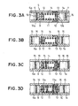
- the valves 12 and 13 usually close the openings of the partitions 9 and 10 respectively. Only when the high pressure portions 15 reaches the inner space 6a or 7a in front of the valve 12 or 13, for example, the valve 12 opens against the spring force of the spring 14 as shown in FIG. 3B . Accordingly, the high pressure portion 15 of the fuel enters the damping chamber 11.
- the trapped high pressure portion 15 in the damping chamber 11 is gradually released to the inner space 6a or 7a via the orifice 12a or 13a as shown in FIG. 3D when a low pressure portion of the pressure wave reaches the inner space 6a or 7a, that is when the fuel pressure in the inner space 6a or 7a is decreased. Accordingly, the fuel pressure of the low pressure portion in the inner space 6a and 7a increases, and the fuel pressure of the high pressure portion in the damping chamber 11 gradually decreases.
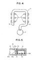
- FIG. 4 A total structure of a fuel supply system 17 as a second unclaimed example of the present invention is shown in FIG. 4 .
- the fuel supply system 17 is applied to a six cylinder V-type engine having six injectors 4 on a single high pressure fuel pipe 19 as shown in FIG. 4 .
- Pressure feed type fuel pump 2 is attached to one end of the high pressure fuel pipe 19, and a pressure relaxation device 18 is attached to the other end of the high pressure fuel pipe 19. If the high pressure fuel pipe 19 is modified to a straight line, the present invention is also applicable to a six cylinder in-line engine.
- Pipe portion 20 of the pressure relaxation device 18 is connected to a tip of the high pressure fuel pipe 19, but it may be a part of the tip of the high pressure fuel pipe 19 instead.
- Inner space 20a of the pipe portion 20 is separated from a damping chamber 22 by a partition 21.
- An opening 21a is formed in the partition 21, and a valve body 23 is provided for closing and opening the opening 21a.
- a small orifice 23a if formed in the valve body 23.
- the valve body 23 is always biased toward the partition 21 by a spring 24.
- One end of the spring 24 is supported by a bottom surface 22a of the damping chamber 22.
- pressurized fuel pressurized by the fuel pump 2 has the pressure pulsation since it has been discharged, and the pressure pulsation is further increased by opening valves of the injectors 4. Since the pressure wave is transmitted in the high pressure fuel pipe 19 from the end to the tip, high pressure portion and low pressure portion reach the inner space 20a in turn.
- the pressure relaxation device 18 is not provided at the tip of the high pressure fuel pipe 19, the pressure wave is reflected at the tip of the high pressure fuel pipe 19 and is transmitted in a reversed direction. Accordingly, the pressure pulsation is increased when the phase of the pressure wave transmitted in one direction and the phase of the pressure wave transmitted in the opposite direction are synchronized, and the injection quantities of the respective injectors 4 fluctuate significantly.
- the pressure relaxation device 18 is provided at the tip of the high pressure fuel pipe 19.
- the valve 23 opens its valve to trap the high pressure portion in the damping chamber 22.
- the high pressure portion (highly pressurized fuel) gradually flows out from the damping chamber 22 via the orifice 23a of the valve body 23. Accordingly, pressure of the low pressure portion is increased, and the pressure pulsation is reduced. Thus, the fluctuation of the injection quantity of the injectors 4 is reduced.
- FIG. 6 shows a pressure relaxation device 25 as a main part in a third unclaimed example of the present invention. Differences between the pressure relaxation device 5 in the first example shown in FIG. 2 and the pressure relaxation device 25 in the third embodiment are that valve bodies 26 and 27 of the pressure relaxation device 25 do not have an orifice and that protrusions 26a and 27a are provided such that a small gap 28 is maintained even if the valve bodies 26 and 27 seat on the partitions 9 and 10.
- the gap 28 functions as the orifices 12a and 13a in the first embodiment.
- the pressure relaxation device 25 operates in substantially the same way as the pressure relaxation device 5 in the first example. By releasing the high pressure portion of the fuel trapped in the damping chamber 11 gradually, the same effect as the first example is obtained.
- the protrusions 26a and 27a may be spacers which allow the fuel to pass through. Such spacers may be provided in the inner space 6a and 7a instead.
- FIG. 7 shows a pressure relaxation device 29 as a main part in a fourth unclaimed example of the present invention.
- Differences between the pressure relaxation device 5 in the first example shown in FIG. 2 and the pressure relaxation device 29 in the fourth example are that valve bodies 30 and 31 of the pressure relaxation device 29 do not have an orifice and that small orifices 9b and 10b are formed in the partitions 9 and 10 such that the damping chamber 11 and the inner space 6a or 7a are communicated each other even if the openings 9a and 10a are closed by the valve bodies 30 and 31.
- FIG. 8 shows a pressure relaxation device 32 as a main part in a fifth unclaimed example of the present invention.
- a difference between the pressure relaxation device 5 in the first example shown in FIG. 2 and the pressure relaxation device 32 in the fifth example is that a valve body 34 does not have an orifice while a valve body 33 has an orifice 33a.
- the high pressure fuel pipe 3 has a loop shape. Therefore, the orifice to relieve the high pressure portion of the fuel trapped in the damping chamber 11 gradually is not necessarily provided at both partitions 9 and 10. Therefore, substantially the same result is obtained by providing the single orifice 33a comparing with providing two orifices.
- FIGS. 9A to 9C show a structure and an operation of the pressure relaxation device 35 as a main part of a sixth unclaimed example of the present invention.
- the pressure relaxation device 35 is also applied to a loop-shaped fuel supply system 1 shown in FIG. 1 , and is provided at the joint portion 3d.
- a characteristic of the sixth example is to insert a bag 36 made of a tough material which is a little flexible but is little extendable into the damping chamber 11 between the partitions 9 and 10 without providing the valve bodies and springs shown in the previous embodiments.
- the bag 36 is made by coating a rubber layer having a certain thickness on a bag made of woven material, such as Kevler fiber.
- the rubber is a synthetic rubber which is hard to be deteriorated by the fuel.
- High pressure inert gas such as gaseous nitrogen which does not deteriorate the rubber and Kevler fiber, fills the bag 36.
- a part of the bag 36 is deformed by the high pressure portion as shown in FIG. 9A .
- the volume of the bag 36 is slightly decreased to absorb the high pressure portion of the pressure wave. Then, when a low pressure portion reaches the inner space 6a or 7a, the bag 36 returns to the initial shape to increase the pressure of the low pressure portion.
- FIG. 9B shows a state of the bag 36 when the high pressure portion of the pressure wave reaches the inner space 6a.
- FIG. 9C shows a state of the bag 36 when the low pressure portion of the pressure wave reaches the inner space 7a.
- FIG. 10 shows a part of manufacturing processes of the bag 36 used for the pressure relaxation device 35. in the sixth example.
- the bag 36 having a hole 36a is obtained by a prior process to unify the rubber with the fiber bag. After setting the bag 36 into a high pressure container 37, high pressure gaseous nitrogen or the like is supplied through an inlet 37a of the container.
- the high pressure gas enters not only the outside of the bag 36 but also the inside of the bag 36 via the hole 36a. After waiting shortly until the inner pressure and the outer pressure are balanced, the hole 36a is filled with raw rubber or the like, and seal it by heating. Accordingly, the bag 36 filled with high pressure gas is obtained.
- liquefied inert gas such as liquid nitrogen
- poured into the bag 36 via the hole 36a and seal the hole 36a immediately.
- the poured liquefied gas turns into the gas phase under the ordinary temperature to sufficiently increase the inner pressure of the bag 36.
- a mechanical valve instead of sealing the hole 36a by the rubber which is the same material used for the bag 36, a mechanical valve may be used, and the high pressure gas may be filled with the bag 36 by opening and closing the valve.
- a fuel supply system 38 of the first embodiment has a structure illustrated in FIG. 11 to apply it to a six cylinder V-type engine.
- the fuel supply system 38 of the first embodiment is an improvement of a conventional fuel supply system 39 illustrated in FIG. 12 .
- the fuel supply system 38 of the first embodiment has a right delivery pipe 40 and a left delivery pipe 41 for the right cylinder group and the left cylinder group of a not shown V-type direct injection engine, that is for the right bank and the left bank respectively.
- Each of the right and left delivery pipes 40 and 41 is made of a pipe-shaped pressure storing container having a large cross section, and has three injectors 4 for injecting fuel into cylinders of the respective banks.
- one end of the right delivery pipe 40 is connected to the discharge side of the fuel pump 2 via a connecting pipe 42, and a part of the right delivery pipe 40 adjacent to the other end of the right delivery pipe 40 is connected to a part of the left delivery pipe 41 adjacent to one end of the left delivery pipe 41 via a connecting pipe 43.
- Respective timing pulleys are attached to a crank shaft 44 and a cam shaft 45 of an engine.
- a timing belt 46 is provided between the timing pulleys to form an ordinary cam driving mechanism.
- a pump-driven cam 47 having three teeth is attached to the cam shaft 45.
- a pump plunger 48 of the fuel pump 2 driven by the pump-driven cam 47 to reciprocate for pressurizing fuel supplied to the injectors 4 is slidably provided in a cylinder.
- design data such as cross sectional are (thickness) and length, of a right and left delivery pipes 40' and 41' and connecting pipes 42' and 43' are different from those in the first embodiment, and it has an orifice 49 in the connecting pipe 42' for relaxing the pressure pulsation.
- resonance frequency of the system is calculated to reduce the pressure pulsation of the fuel, and an impedance method is used therefor.
- Z 0 to Z 4 shown in Table 1 are calculated by changing frequency f by 0.1Hz by a computer.
- Z 0 to Z 4 are impedance for respective parts of the fuel line of the fuel supply system 39.
- the necessary bulk modulus K is one of the physical values of the fuel (gasoline), and it is for example 600MPa.
- total impedance Z is obtained from Z 0 to Z 4 and the following Equation 1.
- Total impedance Z Z 1 + Z 0 + 1 / 1 / Z 2 + 1 / Z 3 + Z 4
- the total impedance Z is an impedance, as a function of the frequency f of the pressure pulsation, of the entire fuel supply system 39 on the basis of the fuel pump 2.
- One frequency f at which the total impedance Z rapidly increases among various frequencies f is determined as the resonance frequency of the fuel supply system 39.
- Frequency or resonance frequency of the pressure pulsation is changed by changing the design data of the system 39 such that the resonance frequency does not coincide with the pressure pulsation frequency of the pressurized fuel in the fuel supply system 39 generated by intermittent discharge of the pressurized fuel from the fuel pump 2 or opening/closing operation of the injectors 4.
- the conventional fuel supply system 39 has the orifice 49 on the connecting pipe 42' or an inlet of the right delivery pipe 40 in order to reduce the pressure pulsation caused by the intermittent fuel discharge by the plunger of the fuel pump 2.
- the orifice 49 needs to have a very fine diameter because the fuel is gasoline.
- the resonance frequency (natural frequency) of the system may resonate with the high frequency of the pressure pulsation because the response is not sufficient for the high frequency, that is a frequency of a harmonics having two or several times bigger than that of the discharge pulsation of the fuel pump 2.
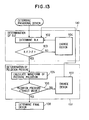
- FIG. 13 illustrates a design calculation program for the fuel supply system 38 by the computer.
- a provisional pipe design for the entire fuel supply system is determined in step 101. For example, it is desirable to prepare in advance several kinds of pipe designs, such as the one for the fuel supply system 38 shown in FIG. 11 . One of them is used for the calculation for an evaluation.
- step 102 the resonance frequency (R.F.) of the fuel supply system 38 used in the previous step 101 is calculated by the conventional impedance method explained in the Table 1 and the Equation 1 herein.
- a predetermined target frequency F under the operation of the fuel supply system 38 is compared with the resonance frequency calculated in the previous step.
- step 103 When it is determined in step 103 that the calculated resonance frequency is not greater than the target frequency F (NO), it proceeds to step 104 because the target frequency of the fuel pump 2 may resonate with the resonance frequency.
- step 104 design data of a part which may generate the resonance, that is, diameters, lengths and the like of the connecting pipes 42, 43 and the right and left delivery pipes 40, 41 are changed in order to increase the resonance frequency. Then, it returns to step 102 to repeat the calculation of the resonance frequency and the determination with the target frequency F described above.
- a first block (a) enclosed by a two-dot chain line shows steps for calculating design data of the fuel supply system 38 necessary for avoiding the resonance and for calculating the resonance frequency.
- the seventh embodiment executes a second block (b) enclosed by a two-dot chain line in FIG. 13 , that is determination processes by pulsation pressure, to confirm whether the resonance is caused by the pressure pulsation, mainly by the harmonics, and the design data, such as the size of the delivery pipes 40, 41 and the connecting pipes 42, 43, may be changed for some cases.
- the fundamental frequency of the pressure pulsation caused by the discharge pulsation of the fuel pump 2 or opening/closing valves of the injectors 4 is relatively small, it is relatively easy to set the resonance frequency of the fuel supply system greater than the fundamental frequency.
- step 103 when it is determined YES in step 103, it proceeds to step 105 to calculate the pressure pulsation wave form of the fuel supply system 38 by the numerical analysis.
- a publicly available computer software may be used for the numerical analysis.
- the waveform and the amplitude of the pressure pulsation is determined.
- at least the reason why several peaks appear on the waveform in the range of the normal engine speed is obtained.
- which harmonics (multiple number of harmonics) of the pressure pulsation in the fuel supply system generates the resonance is determined.
- step 106 an amplitude of the pulsation pressure is compared with a predetermined target value.
- the amplitude of the pulsation pressure is greater than the target value (NO)
- it proceeds to step 107 to change the design data of a part, such as a part which transmits a vibrational force.
- a part such as a part which transmits a vibrational force.
- the bigness or length of the connecting pipe 42 between the fuel pump 2 and the right delivery pipe 40 may be changed, or the cross sectional area of a restriction, such as a small diameter pipe, at the entrance of the delivery pipes 40 and 41 may be changed.
- step 107 After finishing the step 107, it may return to step 105, but according to the flowchart shown in FIG. 7 , it returns to step 102 instead just in case to re-execute the evaluation processes by the frequency in the first block (a) and re-execute the evaluation processes by the amplitude of the pulsation pressure in the second block (b) thereafter.
- step 108 it proceeds to step 108 when it is determined YES in step 106 to manufacture a part of or whole system, confirm the performance by experiments, and determine the final design.
- inner diameters (bigness) or lengths of the connecting pipes 42 or 43 and inner diameters (bigness) or lengths of the delivery pipes 40 or 41 for determining the volume of the delivery pipes 40 or 41 are the "design data”.
- FIGS. 14A, 14B and 14C show how the resonance frequency varies when the inner diameter and length of the connecting pipe 43 and the total volume of the delivery pipes 40 and 41 are changed respectively.
- the volume is a total volume of right and left delivery pipes 40 and 41.
- the resonance frequency shown by the peak of the impedance Z significantly shifts toward the higher frequency when the inner diameter of the connecting pipe 43 is increased.
- the resonance frequency slightly (not significantly) shifts toward the higher frequency when the length of the connecting pipe 43 is shortened.
- the resonance frequency slightly (not significantly) shifts toward the higher frequency when the total volume of the delivery pipes 40 and 41 is reduced.
- the fundamental frequency of the discharge pulsation of the fuel pump 2 is 150Hz
- the second higher harmonics frequency is 300Hz
- the third higher harmonics frequency is 450Hz.
- a frequency shown by the peak of the total impedance Z of the fuel supply system is a resonance frequency corresponding to the design data shown in FIGS. 14A to 14C .
- the height of the peak of the total impedance Z is not necessarily showing the strength (amplitude) of the resonance. A strong resonance may occur even if the height of the peak is low.
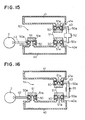
- a fuel supply system of a second embodiment of the present invention shown in FIG. 15 has been developed based on the system design method explained in the first embodiment and informations regarding the change of the design data obtained by various studies of the design method and shown in FIGS. 14A to 14C . In that sense, the following seventh to ninth examples of the present invention illustrated in FIGS. 16 to 18 are similar to the second embodiment.
- protruded portions 40a and 41a protruding to each other are formed on the delivery pipes 40 and 41 respectively.
- the protruded portions 40a, 41a and a ring 50 and a union bolt 51 are integrated in a fluid-tight manner because an external thread of the union bolt 51 is screwed in an internal thread of the protruded portions 40a, 41a via the ring 50 having a U-shaped cross section and a washer or a seal ring or the like.
- the union bolt 51 has a communication hole 51a for communicating the inside of the protruded portion 40a or 41a, that is the inside of the delivery pipe 40 or 41, with the inside of the ring 50.
- the ring 50 has a communication hole 50a. Both ends of the connecting pipe 43 are connected to the ring 50 by welding or the like such that the delivery pipes 40 and 41 are connected at the communication hole 50a.
- the connecting pipe 43 has a U shape because the connecting pipe 43 is connected to the protruded portions 40a and 41a at the side of the ring 50.
- the reason of this shape is that it is often difficult to connect the protruded portions 40a and 41a with the straight connecting pipe 43 because an intake air system or the like is usually provided between the two banks of the V-type engine. If there is no obstacle between the protruded portions 40a and 41a, it is better to use a shorter and straight connecting pipe 43.
- the first feature of the second embodiment is to provide an enlarged volume portion 52 having an enlarged diametrical portion on a part of the connecting pipe 43 connecting the protruded portions 40a and 41a.
- the second feature of the second embodiment is to set the effective diameter of the inner space of the protruded portions 40a, 41a is set greater than the inner diameter of the connecting pipe 43 even after screwing the union bolt 51. Accordingly, average diameter and volume of the connecting portion between the delivery pipes 40 and 41 are significantly increased comparing to those of the connecting pipe 43.
- the third feature of the second embodiment is that the length of the connecting pipe 43 is substantially shortened by protruding the protruded portions 40a and 41a to each other.
- the connecting pipe 42 is connected to the right delivery pipe 40 to receive the pressurized fuel from the fuel pump 2.
- the connecting portion between the right delivery pipe.40 and the connecting pipe 42 comprises a protruded portion 40b which has a similar shape to the protruded portions 40a, 41a, and the ring 50 and the union bolt 51.
- the connecting portion between the right delivery pipe 40 and the connecting pipe 42 may employ other shape and structure.
- the enlarged volume portion 52 formed on the connecting pipe 43 and the inner space having the enlarged effective inner diameter of the protruded portions 40a and 41a significantly enlarge the average inner diameter of the connecting portion between the delivery pipes 40 and 41 including the connecting pipe 43.
- the fundamental frequency, that is the natural frequency, of the fuel supply system 53 is significantly increased as apparent from FIG. 14A regarding the explanation in the first embodiment.
- a fuel supply system 54 of a seventh unclaimed example of the present invention is illustrated in FIG. 16 .
- the difference between the second embodiment and the seventh unclaimed example is that the enlarged volume portion 52 in the second embodiment is replaced by a flexible member 55 which is slightly flexible, thick and rigid made of a strong and oilproof synthetic rubber or the like.
- the flexible member 55 has an enlarged diameter portion similar to the enlarged volume portion 52 in the eighth embodiment, the resonance frequency of the fuel supply system 54 in the ninth embodiment is increased, and the occurrence of the resonance with the pressure pulsation in the system 54 is prevented. Furthermore, since the connecting pipe 43 has a flexibility, the assembly of an engine is facilitated, and breakage of a connecting portion, such as the connecting pipe 43, caused by the vibration of an engine is prevented.
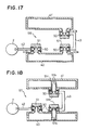
- a fuel supply system 56 of a an eigth unclaimed example of the present invention is illustrated in FIG. 17 .
- the difference between the second embodiment or the seventh example and the eigth example is that the volume of the downstream side left delivery pipe 41' is greater than that of the upstream side right delivery pipe 40 in the eigth example.
- the pulsation width (amplitude) of the pressure pulsation of the pressurized fuel in the right delivery pipe 40 and that in the left delivery pipe 41' are different because the right delivery pipe 40 and the left delivery pipe 41' are connected in series via the connecting pipe 43 having relatively small diameter.
- the volume of the left delivery pipe 41' is increased such that the pulsation width of the pressure pulsation in the left delivery pipe 41' becomes the same as the one in the right delivery pipe 40. Accordingly, fluctuation of fuel injection quantity between the cylinders of the left bank and the right bank.
- a fuel supply system 57 of a ninth unclaimed example of the present invention is illustrated in FIG. 18 .
- a union bolt 51' is longer than the union bolt 51 and the inside of the delivery pipe 40 and/or 41 are/is divided into several small rooms in the ninth example.
- the union bolt 51' does not completely divide the inside of the delivery pipe.
- the union bolt 51' has a communication hole 51b or forms a gap 51c between a tip thereof and the delivery pipe for allowing the fuel flow from one divided room to the other divided room(s).
- the resonance frequency (natural frequency) of the delivery pipes 40 and 41 is increased by dividing the inside of the delivery pipes 40 and/or 41 into several small rooms because of the same reason described above with reference to FIG. 14C . Accordingly, the pressure pulsation and the resonance with its harmonics are prevented.
- the total impedance Z is calculated by determining the respective impedances Z 0 to Z 4 of the system (see Table 1) and summating them according to the Equation 1 when the resonance frequency, that is the natural frequency, of the fuel supply system shown in FIG. 12 is calculated.
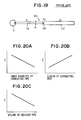
- a conventional fuel supply system 39' shown in FIG. 19 having simpler structure than the one shown in FIG. 12 is known as a fuel supply system which is capable of being used for an inline type multiple cylinder engine.
- a plurality of injectors are installed in a single delivery pipe 40' to inject fuel directly to respective cylinders.
- a tip of the downstream side of the connecting pipe 42 connected to the fuel pump 2 supplies pressurized fuel to the delivery pipe 40' via the restricted orifice 49 which is to reduce the pressure pulsation.
- the resonance frequency of the system should be shifted to the higher frequency side by reducing the total impedance Z of the piping system as much as possible.
- parameters for increasing or decreasing the total impedance Z should be determined as follows because of the reasons shown in FIGS. 20A to 20C :
- the impedance Z 1 of the connecting pipe 42 is equal to 2 ⁇ fm 1 j as described in Table 1.
- the impedance Z 1 of the connecting pipe 42 is decreased in inverse proportion to d 1 squared.
- the change of the inner diameter d 1 of the connecting pipe 42 has the greatest influence among the above three kinds of parameters.
- the inner diameter d 1 of the connecting pipe 42 should be as large as possible as described above to reduce the impedance Z 1 , that is the total impedance Z.
- FIG. 21 A fuel supply system of a tenth unclaimed example of the present invention utilizing the above fact and the nature is illustrated in FIG. 21 .
- a connecting portion 58a which connects a delivery pipe 58 to the fuel pump 2 is integrally formed with the delivery pipe 58, and has a large diameter.
- the connecting pipe 42' and the connecting portion 58a have high rigidity, the flexible member 55 makes the structure flexible, and facilitates the assembly. Furthermore, a restricted orifice 49' is provided between the fuel pump 2 and the connecting pipe 42' as an auxiliary means for reducing the pressure pulsation.
- the restricted orifice 49 is required to have a very small diameter. Therefore, it has various problems that foreign matters tend to stuck at the restricted orifice 49, certain fuel injection quantity may not be secured, it may be difficult to dry the inside of the system after the surface treatment in the manufacturing process, and the like.
- the restricted orifice 49' is the auxiliary means for reducing the pressure pulsation and is not the sole pressure pulsation reducing means. Accordingly, the effective diameter of the restricted orifice 49' may be larger than that of the prior art without causing the problems described in the above prior art.
- the impedance Z 3 of the connecting pipe 43 is equal to 2 ⁇ fm 3 j as described in Table 1.
- the impedance Z 3 of the connecting pipe 43 is decreased in inverse proportion to d 3 squared.
- FIG. 22 A fuel supply system of a eleventh example of the present invention utilizing the above fact and the nature is illustrated in FIG. 22 .
- Delivery pipes 60 and 61 are integral-type delivery pipes. Large-diameter connecting portions 60a and 61a are integrally formed with the delivery pipes 60 and 61 respectively for connecting the right delivery pipe 60 to the left delivery pipe 61. Based on the same reason as described above, the connecting portions 60a and 61a are connected via the flexible member 55.
- connecting pipe 42 which connects the upstream side delivery pipe 60 to the fuel pump 2 has an ordinary diameter, and a large-diameter restricted orifice 49' as an auxiliary means for reducing the pressure pulsation is provided between the connecting pipe 42 and the delivery pipe 60.
- integrally formed connecting portions 60b and 61b are provided on the delivery pipes 60 and 61 as well as the connecting portions 60a and 61a. Further, these connecting portions 60b and 61b are connected via the flexible member 55. Accordingly, the high pressure piping of the fuel supply system 63 has a looped-shape.
- the loop-shaped high pressure piping and the fuel pump 2 are connected via the connecting pipe 42 similarly to the one in the eleventh example
- the total impedance Z is reduced to increase the resonance frequency by increasing the diameter of the connecting portion of the delivery pipe. Accordingly, the pressure pulsation in a normal drive range of an engine and the synchronization with a frequency of the harmonics are prevented, and the resonance is prevented.
- a fuel supply system 67 of a thirteenth unclaimed example of the present invention is illustrated in FIG. 24 .
- the fuel supply system 67 has right and left delivery pipes 64 and 65 for a plurality of injectors 4 toward the right and left banks of a V-type engine.
- the delivery pipes 64 and 65 are connected to each other on entire opposing surfaces without using a connecting pipe or the like to form a unified flat delivery pipe having a large volume.
- the entire opposing surfaces are connected via a flexible member 66. Accordingly, the right and left delivery pipes 64 and 65 are slightly movable each other, and thereby facilitating the assembly.
- the right and left delivery pipes 64 and 65 are connected via the large connecting portion, and the unified delivery pipe has a significant volume. Accordingly, based on the characteristics shown in FIGS. 20A and 20C , the total impedance Z is significantly reduced, and the resonance frequency is increased, and the resonance is hard to occur in the normal drive range of an engine.
- a fuel supply system 71 of a fourteenth unclaimed example similar to the thirteenth example is illustrated in FIG. 25 .
- first delivery pipe 68 and second delivery pipe 69 are connected in series via a flexible member 70 on entire end surfaces of the opposing delivery pipes 68 and 69. Furthermore, the first delivery pipe 68 is connected to the fuel pump 2 via large-diameter restricted orifice 49'.
- the large-diameter restricted orifice 49' is provided in the fuel supply system 71 of the fourteenth example, it may be omitted if the pressure pulsation is sufficiently reduced because providing the restricted orifice is not essential for the present invention.
- a fuel supply system 72 of a fifteenth unclaimed example is illustrated in FIG. 26 .
- the structure of the main portion of the fuel supply system 72 is illustrated in FIGS. 27A and 27B .
- the main feature of the fifteenth example is to provide a directional restricted orifice 75 on at least one of the connecting pipe 42 and at least one of a plurality of connecting pipes 74.
- the connecting pipe 42 connects the fuel pump 2 to a delivery pipe 73, and the connecting pipes 74 connect the delivery pipe 73 to the injectors 4.
- the restricted orifice 75 which is directional shown in FIGS. 27A and 27B has a conical shape and is made of elastic material such as a spring steel plate or an oilproof synthetic rubber.
- the restricted orifice 75 has a small opening 75a on its center and a plurality of slits 75b radially formed from the opening 75a.
- FIG. 26 illustrates an example that the restricted orifice 75 is installed in a middle of the connecting pipe 42, and the restricted orifice 75 is installed in the connecting pipe 42 such that the tip of the conical shape protrudes toward the downstream side with respect to the fuel pump 2.
- the opening 75a of the restricted orifice 75 not only the opening 75a of the restricted orifice 75 but also the slits 75b form a large diameter passage for the pressurized fuel flow in a positive direction represented by an arrow illustrated in FIG. 26 when the pressurized fuel is supplied from the fuel pump 2 to the injectors 4 via the connecting pipe 42 or the connecting pipe 74. Accordingly, the pressurized fuel flows with very little resistance from the fuel pump 2 to the delivery pipe 73 and the injectors 4.
- the reverse flow is reduced. Further, the pressure wave transmission in a reversed direction is substantially prevented because the pressure wave proceeding in the reversed direction receives a large resistance. Furthermore, generation of the vibration and the noise of the high pressure pipes is also prevented.
- the restricted orifice 75 is made of a material such as a rubber having a flexibility, similar result is obtained without forming the slits 75b because the restricted orifice 75 has a direction created only by expansion and shrinkage of the opening 75a.
- a reed valve which allows only one way flow to the downstream side and to have an orifice formed in the reed valve itself or a partition wall around the reed valve for bypassing the reed valve in order to form a directional orifice.
- the opening always expands and shrinks, and it has a substantially large opening cross section. Therefore, a choke caused by a foreign object is prevented.
- the fuel pump 76 in the sixteenth unclaimed example includes a cylinder block 77, a drive shaft 79 inserted from the outside into a cum chamber 78 formed in the cylinder block 77, an approximately equilateral triangle shaped cam 80 attached to the drive shaft 79, a pair of cylinders 81 and 82 formed in the cylinder block 77 such that they face each other from 180 degree opposite direction with respect to the drive shaft 79, and a pair of plungers 83 and 84 which are slidably inserted in the cylinders 81 and 82 and whose inner ends are contacting different surfaces of the cam 80.
- a pair of pressure chambers 85 and 86 are formed facing respective outer ends of the plungers 83 and 84 as a space in the cylinder block 77.
- a pair of divided inlet passages 87 and 88 connected to respective pressure chambers 85 and 86 via an inlet valve not shown, a common inlet chamber 89 connected to upstream side ends of the divided inlet passages 87 and 88, and an inlet passage 90 connected to a low pressure fuel pump (not shown) located at the upstream side are formed.
- inlet valve provided between the pressure chambers 85, 86 and the divided inlet passages 87, 88 or the outlet valve provided between the pressure chambers 85, 86 and the divided outlet passages 91, 92
- inlet valve or an outlet valve which is a check valve type or an opening of a cylinder which is opened/closed by a plunger when the plunger slides, similarly to a conventional ones which have been used for a fuel injection pump.
- the ordinate corresponds to fuel pressure
- the abscissa corresponds to rotation angle of the drive shaft 79 and the cam 80.
- the discharge pulsation of the pressurized fuel introduced from the discharge passage 94 of the fuel pump 76 disappears. Accordingly, the pressurized fuel which has substantially constant pressure is supplied to a delivery pipe not shown, and it is distributed to injectors for respective cylinders. Thus, the fluctuation of the fuel injection quantity and vibrations of the engine and the like caused by the discharge pulsation of the fuel pump are prevented.
- the pressure pulsations in the pressure chambers 85 and 86 are canceled each other in the discharge chamber 93 because the pressure pulsations in the pressure chambers 85 and 86 have the phase difference of one half of the wavelength by defining the locations of a pair of cylinders 81 and 82 in the cylinder block 77, that is by locating the plunger 83 opposite to the plunger 84 by 180 degrees as described in the sixteenth example shown in FIG. 28 .
- the angle between a pair of plungers 83 and 84' is set to 60 degrees according to a fuel pump 95 of a seventeenth unclaimed example shown in FIG. 30 in order to generate a pair of pressure pulsations having a phase difference of one half of the wavelength.
- the angle between a pair of plungers 83 and 84' may be set to 300 degrees instead.
- the wavelengths of the pressure pulsations generated in the pressure chambers of a pair of cylinders are deviated from each other by one half of the wavelength when the pair of cylinders are placed on the cylinder block 77 around the drive shaft 79 such that the angular locations of the cylinders are n ⁇ /2, wherein ⁇ represents an angle between the protrusions, and n represents a random integer. Accordingly, if the pressurized fuel generated in these two pressure chambers is simultaneously introduced to the common discharge chamber 93, the both pressure pulsations cancel each other, thereby reducing the pressure pulsation.
- FIGS. 28 and 30 having a pair of cylinders are disclosed.
- the number of the cylinders of the fuel pump may be three or greater.
- the angular locations of a plurality of cylinders are defined to deviate the phase such that the pressure pulsations are canceled each other when pressurized fuel having the pressure pulsations generated in respective pressure chambers of the cylinders meet in the common discharge chamber.
- the approximately equilateral triangle shaped cam 80 it is generally possible to use another cam having any shape such as a polygonal cam.
- the angular locations of the cylinders are defined n ⁇ /2 as described above based on the relationship between the angular locations of the cam protrusions if the cylinders are a pair of cylinders.
- a fuel pump 96 in an eighteenth unclaimed example of the present invention has an elliptic cam 97 whose shape is close to a rhombus.
- the plungers of the fuel pump are rotatably driven by the cam.
- the plunger may be replace by a piston which is reciprocated by a crank mechanism, an eccentric wheel mechanism or the like.
- a plurality of cylinders and a plurality of plungers are radially located around a polygonal cam having a drive shaft as a radial center to form a multi-cylinder pump having a star shape as a whole, and the discharge pulsations are canceled each other by defining the relative angular locations of the plural cylinders.
- a plurality of cylinders parallel to the drive shaft on a surface of a hypothetical cylinder having a central axis aligned with the drive shaft, and to reciprocate the plungers in its axial direction by using a common face cam having a wave-shaped edge in the axial direction.
- a plurality of cylinders are located, similarly to the above star-shaped locations, such that they have certain relationships regarding the angular locations with respect to the drive shaft.
- a damping chamber (11, 22) is formed in a pressure relaxation device (5, 18) connected to a high pressure fuel pipe (3, 19).
- Valve bodies (12, 13, 23, 26, 27, 30, 31, 33, 34) are provided at openings of partitions (9, 10, 21), and a spring force is applied to the valve bodies by a spring (14, 24) in a valve closing direction.
- a high pressure portion reaches an inlet (9a, 10a, 21a) of the damping chamber, the valve body opens to hold and absorb the high pressure portion in the damping chamber.
Landscapes
- Engineering & Computer Science (AREA)
- Chemical & Material Sciences (AREA)
- Combustion & Propulsion (AREA)
- Mechanical Engineering (AREA)
- General Engineering & Computer Science (AREA)
- Fuel-Injection Apparatus (AREA)
Description
- The present invention relates to a method of designing a fuel supply system which relieves fuel pressure pulsations in a fuel line of an internal combustion engine such as a direct injection engine which directly injects fuel into a cylinder.
- According to a direct injection engine, it may inject fuel into a highly pressurized cylinder at a compression stroke. Therefore, pressure of fuel supplied to an injector is set higher than that of a conventional engine which injects fuel into an intake port having a low pressure.
- The fuel is intermittently discharged to a common high pressure fuel pipe at a fuel discharge pump, such as a fuel injection pump, by a plunger which is driven by a cam to reciprocate. Accordingly, high pressure pulsation is generated in fuel in the high pressure fuel pipe according to the shape of the cam. In addition, the pressure in the high pressure fuel pipe is temporarily reduced because each one of a plurality of injectors connected to the common high pressure fuel pipe intermittently opens its valve respectively to inject fuel. As a result, pressure pulsations having high pressure and low pressure are generated in fuel flowing in the high pressure fuel pipe, and proceed in the high pressure fuel pipe as pressure waves.
- Accordingly, whether the pressure pulsation having high pressure or the pressure pulsation having low pressure is at a fuel supply port of an injector when the injector opens its valve changes fuel injection quantity even if the injector opens its valve at the same timing.
- Such injection quantity fluctuation caused by the pressure pulsation in the high pressure fuel pipe is also generated on the conventional engine which injects fuel into the intake port as long as a plurality of injectors are connected to a common fuel pipe to receive fuel. In order to solve this problem,
JP-U-57-100,693 - However, an injection pressure of the injector and a fuel pressure in the fuel line for the direct injection engine are higher than those for the conventional engine. Therefore, such injection quantity fluctuation for each one of the injectors for the direct injection engine may be greater.
- If a conventional pressure damper comprising a soft damping member, such as a diaphragm or a bellows, is applied to a high pressure fuel pipe of the direct injection engine, the damping member may be easily broken because the fuel pressure in the high pressure fuel pipe of the direct injection engine is high. In that case, sufficient durability and reliability can not be obtained. If a full accumulator is employed in order to relieve the pressure in the high pressure fuel pipe of the direct injection engine, the whole apparatus is increased in size and cost because the accumulator itself is large and expensive.
- According to a V-type engine, single fuel line is separated into two pipes toward two banks and joined together at their ends to form a loop. According to such loop-shaped fuel line, crests or troughs of the pressure waves progressing in the respective separated fuel pipes may meet at the joint of the pipes. In that case, the pressure pulsation is magnified by summating respective crests or respective troughs, and a big pressure wave progresses in the fuel line in a reversed direction.
- Furthermore, the pressure pulsation is magnified by resonance when a pressure pulsation frequency approaches a natural frequency of the fuel line.
- Such magnified pressure pulsations may cause further fluctuation of the injection quantity.
-
JP-A-10-73,062 - Further,
JP-A-9-170514 EP 0 780 569 - The present invention is made in light of the foregoing problem, and it is an object of the present invention to provide a method which reduces pressure pulsation in a high pressure fuel pipe and which has high durability and reliability.
- This object is solved by a method having the features of
claim 1. A further development thereof is stated inclaim 2. - Accordingly, discharge pulsation is not substantially included in pressurized fuel discharged from the common discharge chamber. Thus, a fuel injection quantity fluctuation of the injectors for respective cylinders and a vibration occurrence are prevented.
- Other features and advantages of the present invention will be appreciated, as well as methods of operation and the function of the related parts, from a study of the following detailed description, the appended claims, and the drawings, all of which form a part of this application. In the drawings:
-
FIG. 1 is a schematic illustration showing a plan view of an entire structure of a fuel supply apparatus according to a first unclaimed example of the present invention; -
FIG. 2 is a longitudinal sectional view showing a pressure relaxation device according to the first example of the present invention; -
FIGS. 3A to 3D are longitudinal sectional views showing operations of the pressure relaxation device according to the first example of the present invention; -
FIG. 4 is a schematic illustration showing a plan view of an entire structure of a fuel supply apparatus according to a second unclaimed example of the present invention; -
FIG. 5 is a longitudinal sectional view showing a pressure relaxation device according to the second example of the present invention; -
FIG. 6 is a longitudinal sectional view showing a pressure relaxation device according to a third unclaimed example of the present invention; -
FIG. 7 is a longitudinal sectional view showing a pressure relaxation device according to a fourth unclaimed example of the present invention; -
FIG. 8 is a longitudinal sectional view showing a pressure relaxation device according to a fifth unclaimed example of the present invention; -
FIGS. 9A to 9C are longitudinal sectional views showing operations of the pressure relaxation device according to a sixth unclaimed example of the present invention; -
FIG. 10 is a perspective illustration showing a manufacturing process of an inner bag used for the pressure relaxation device according to the sixth example of the present invention; -
FIG. 11 is a schematic illustration showing a fuel supply system to be designed by a designing method according to a first embodiment of the present invention; -
FIG. 12 is a schematic illustration showing a fuel supply system according to a prior art; -
FIG. 13 is a flowchart showing the designing method according to the first embodiment of the present invention; -
FIG. 14A is a graph showing a relation between an inner diameter of a connecting pipe and a resonance frequency and a total impedance of the fuel supply system according to the first embodiment of the present invention; -
FIG. 14B is a graph showing a relation between a length of the connecting pipe and the resonance frequency and the total impedance of the fuel supply system according to the first embodiment of the present invention; -
FIG. 14C is a graph showing a relation between a total volume of a delivery pipe and the resonance frequency and the total impedance of the fuel supply system according to the first embodiment of the present invention; -
FIG. 15 is a schematic illustration showing a fuel supply system according to a second embodiment of the present invention; -
FIG. 16 is a schematic illustration showing a fuel supply system according to a seventh unclaimed example of the present invention; -
FIG. 17 is a schematic illustration showing a fuel supply system according to a eight unclaimed example of the present invention; -
FIG. 18 is a schematic illustration showing a fuel supply system according to a ninth unclaimed example of the present invention; -
FIG. 19 is a schematic illustration showing a fuel supply system according to a prior art; -
FIG. 20A is a graph showing a relation between an inner diameter of a connecting pipe and an impedance of a fuel supply system according to a tenth unclaimed example of the present invention; -
FIG. 20B is a graph showing a relation between a length of the connecting pipe and the impedance of the fuel supply system according to the tenth example of the present invention; -
FIG. 20C is a graph showing a relation between a total volume of a delivery pipe and the impedance of the fuel supply system according to the tenth example of the present invention; -
FIG. 21 is a schematic illustration showing a fuel supply system according to the tenth example of the present invention; -
FIG. 22 is a schematic illustration showing a fuel supply system according to an eleventh unclaimed example of the present invention; -
FIG. 23 is a schematic illustration showing a fuel supply system according to a twelth unclaimed example of the present invention; -
FIG. 24 is a schematic illustration showing a fuel supply system according to a thirteenth unclaimed example of the present invention; -
FIG. 25 is a schematic illustration showing a fuel supply system according to a fourteenth unclaimed example of the present invention; -
FIG. 26 is a schematic illustration showing a fuel supply system according to a fifteenth unclaimed example of the present invention; -
FIG. 27A is an enlarged front view of a main part ofFIG. 26 according to the fifteenth example of the present invention; -
FIG. 27B is an enlarged side view of a main part ofFIG. 26 according to the fifteenth example of the present invention; -
FIG. 28 is a sectional view showing a part of a pressure feed type fuel pump according to a sixteenth unclaimed example of the present invention; -
FIGS. 29A to 29C are graphs showing a relation between a rotation angle and pressure to explain an operation according to the sixteenth example of the present invention; -
FIG. 30 is a schematic illustration showing a main part of a pressure feed type fuel pump according to a seventeenth unclaimed example of the present invention; and -
FIG. 31 is a schematic illustration showing a main part of a pressure feed type fuel pump according to an eighteenth unclaimed example of the present invention. - Embodiments of the present invention will be described hereinafter with reference to the drawings.
- A total structure of a
fuel supply system 1 as a first unclaimed example of the present invention is shown inFIG. 1 . Thefuel supply system 1 is applicable to a six cylinder V-type engine, and includes a pressure feedtype fuel pump 2 for pressurizing fuel for injection, a highpressure fuel pipe 3 and sixinjectors 4a to 4f for injecting fuel to respective six cylinders not shown. - The high
pressure fuel pipe 3 includes abase 3a for connecting thefuel pump 2,branch portions 3b and 3c which diverge to a left bank and a right bank of the V-type engine respectively, and ajoint portion 3d for connecting thebranch portions 3b and 3c at their ends. Thebranch portions 3b and 3c and thejoint portion 3d form a loop. - The
left branch 3b has threeinjectors 4a to 4c for three cylinders which belong to the left bank. The right branch 3c has three injectors 4d to 4f for three cylinders which belong to the right bank. - A
pressure relaxation device 5 shown inFIG. 2 is provided at thejoint portion 3d to absorb the pressure pulsation, and thereby reducing the fluctuation of the injection quantity at theinjectors 4a to 4f. - Detailed structure of the
pressure relaxation device 5 shown inFIG. 2 will now be described. - The end portions of the
left branch 3b and the right branch 3c respectively correspond to aleft pipe 6 and aright pipe 7 which form thejoint portion 3d. The left andright pipes left branch 3b and the right branch 3c instead. - The
left pipe 6 and theright pipe 7 are connected each other by a screwedportion 8.Partitions left pipe 6 and theright pipe 7 respectively to form a dampingchamber 11. - The
partitions openings Disk valves respective openings partitions spring 14 located between thedisk valves partitions disk valves -
Orifices openings disk valves inner space 6a of theleft pipe 6 andinner space 7a of theright pipe 7 are always communicated with the dampingchamber 11 via theorifices disk valves disk valves spring 14 and thedisk valves - High pressurized fuel pressurized by the
fuel pump 2 is separated to theleft branch 3b and the right branch 3c from thebase 3a, and is injected directly to the cylinders as a fuel spray when therespective injectors 4a to 4f for the left and right banks of the six cylinder V-type engine open their valves. - When the fuel is pressurized by a plunger (not shown) of the
fuel pump 2 and discharged to thebase 3a of the highpressure fuel pipe 3, the plunger reciprocates and the pressure pulsations are generated.High pressure portions 15 of fuel are intermittently generated and are transmitted as pressure waves from thebase 3a to the left andright branches 3b and 3c in a fuel flowing direction, and reach thepressure relaxation device 5 from both sides as shown inFIG. 3A . - The
valves partitions high pressure portions 15 reaches theinner space valve valve 12 opens against the spring force of thespring 14 as shown inFIG. 3B . Accordingly, thehigh pressure portion 15 of the fuel enters the dampingchamber 11. - When the fuel pressure in the
inner space 6a decreases thereafter, thevalve 12 closes as shown inFIG. 3C to hold thehigh pressure portion 15 in the dampingchamber 11. Under this situation, anotherhigh pressure portion 15 reached theright valve 13 to open it, and thehigh pressure portion 15 in theinner space 7a is about to enter the dampingchamber 11. - The trapped
high pressure portion 15 in the dampingchamber 11 is gradually released to theinner space orifice FIG. 3D when a low pressure portion of the pressure wave reaches theinner space inner space inner space chamber 11 gradually decreases. - As a result, reflections of the high pressure portion and the low pressure portion at the
partition - Furthermore, an increase of the pressure pulsation transmitting in the high
pressure fuel pipe 3 caused by the oscillation is prevented by thepressure relaxation device 5. - Accordingly, when the
pressure relaxation device 5 is provided at thejoint portion 3d even for thefuel supply system 1 having the loop shape frequently applied to the six cylinder V-type engine, a collision between the high pressure portion and the low pressure portion at thejoint portion 3d is prevented. Thus, the fuel pressure pulsation is effectively prevented, and an injection quantity fluctuation of theinjector 4 is prevented. - A total structure of a
fuel supply system 17 as a second unclaimed example of the present invention is shown inFIG. 4 . - In this and the following examples and embodiments, parts and components which are substantially the same as those in previous examples are assigned the same reference numerals.
- In the second example, the
fuel supply system 17 is applied to a six cylinder V-type engine having sixinjectors 4 on a single highpressure fuel pipe 19 as shown inFIG. 4 . Pressure feedtype fuel pump 2 is attached to one end of the highpressure fuel pipe 19, and apressure relaxation device 18 is attached to the other end of the highpressure fuel pipe 19. If the highpressure fuel pipe 19 is modified to a straight line, the present invention is also applicable to a six cylinder in-line engine. - The
pressure relaxation device 18 will now be described referring toFIG. 5 .Pipe portion 20 of thepressure relaxation device 18 is connected to a tip of the highpressure fuel pipe 19, but it may be a part of the tip of the highpressure fuel pipe 19 instead.Inner space 20a of thepipe portion 20 is separated from a dampingchamber 22 by apartition 21. - An
opening 21a is formed in thepartition 21, and avalve body 23 is provided for closing and opening theopening 21a. Asmall orifice 23a if formed in thevalve body 23. - The
valve body 23 is always biased toward thepartition 21 by aspring 24. One end of thespring 24 is supported by abottom surface 22a of the dampingchamber 22. - Operations of the
fuel supply system 17 according to the second embodiment is similar to those in the first example. - In other words, pressurized fuel pressurized by the
fuel pump 2 has the pressure pulsation since it has been discharged, and the pressure pulsation is further increased by opening valves of theinjectors 4. Since the pressure wave is transmitted in the highpressure fuel pipe 19 from the end to the tip, high pressure portion and low pressure portion reach theinner space 20a in turn. - If the
pressure relaxation device 18 is not provided at the tip of the highpressure fuel pipe 19, the pressure wave is reflected at the tip of the highpressure fuel pipe 19 and is transmitted in a reversed direction. Accordingly, the pressure pulsation is increased when the phase of the pressure wave transmitted in one direction and the phase of the pressure wave transmitted in the opposite direction are synchronized, and the injection quantities of therespective injectors 4 fluctuate significantly. - According to the second example however, the
pressure relaxation device 18 is provided at the tip of the highpressure fuel pipe 19. When the high pressure portion of the pressure wave reaches theinner space 20a, thevalve 23 opens its valve to trap the high pressure portion in the dampingchamber 22. - Then, when the low pressure portion reaches the
inner space 20a, the high pressure portion (highly pressurized fuel) gradually flows out from the dampingchamber 22 via theorifice 23a of thevalve body 23. Accordingly, pressure of the low pressure portion is increased, and the pressure pulsation is reduced. Thus, the fluctuation of the injection quantity of theinjectors 4 is reduced. -
FIG. 6 shows apressure relaxation device 25 as a main part in a third unclaimed example of the present invention. Differences between thepressure relaxation device 5 in the first example shown inFIG. 2 and thepressure relaxation device 25 in the third embodiment are thatvalve bodies pressure relaxation device 25 do not have an orifice and thatprotrusions small gap 28 is maintained even if thevalve bodies partitions - According to the third example, the
gap 28 functions as theorifices pressure relaxation device 25 operates in substantially the same way as thepressure relaxation device 5 in the first example. By releasing the high pressure portion of the fuel trapped in the dampingchamber 11 gradually, the same effect as the first example is obtained. - The
protrusions inner space -
FIG. 7 shows apressure relaxation device 29 as a main part in a fourth unclaimed example of the present invention. Differences between thepressure relaxation device 5 in the first example shown inFIG. 2 and thepressure relaxation device 29 in the fourth example are thatvalve bodies pressure relaxation device 29 do not have an orifice and thatsmall orifices 9b and 10b are formed in thepartitions chamber 11 and theinner space openings valve bodies - According to the fourth example, the same effect and advantage are obtained.
-
FIG. 8 shows apressure relaxation device 32 as a main part in a fifth unclaimed example of the present invention. A difference between thepressure relaxation device 5 in the first example shown inFIG. 2 and thepressure relaxation device 32 in the fifth example is that avalve body 34 does not have an orifice while avalve body 33 has anorifice 33a. - Since the entire structures in the third to the fifth examples are substantially the same as the one shown in
FIG. 1 , the highpressure fuel pipe 3 has a loop shape. Therefore, the orifice to relieve the high pressure portion of the fuel trapped in the dampingchamber 11 gradually is not necessarily provided at bothpartitions single orifice 33a comparing with providing two orifices. - From the same reason, substantially the same result is obtained even if the two orifices or the two gaps are reduced to single orifice or gap. (Sixth unclaimed example)
-
FIGS. 9A to 9C show a structure and an operation of thepressure relaxation device 35 as a main part of a sixth unclaimed example of the present invention. - The
pressure relaxation device 35 is also applied to a loop-shapedfuel supply system 1 shown inFIG. 1 , and is provided at thejoint portion 3d. - A characteristic of the sixth example is to insert a
bag 36 made of a tough material which is a little flexible but is little extendable into the dampingchamber 11 between thepartitions - For example, the
bag 36 is made by coating a rubber layer having a certain thickness on a bag made of woven material, such as Kevler fiber. In this case, the rubber is a synthetic rubber which is hard to be deteriorated by the fuel. High pressure inert gas, such as gaseous nitrogen which does not deteriorate the rubber and Kevler fiber, fills thebag 36. - Accordingly, strong tension is applied to the
bag 36 because of the pressurized gas inside thebag 36. However, the volume of thebag 36 does not exceed a certain volume. - According to the sixth example, when a high pressure portion caused by the pressure pulsation of the fuel supplied through the high
pressure fuel pipe 3 reaches theinner space chamber 11 via theopening bag 36 is inserted in the dampingchamber 11. - Accordingly, a part of the
bag 36 is deformed by the high pressure portion as shown inFIG. 9A . The volume of thebag 36 is slightly decreased to absorb the high pressure portion of the pressure wave. Then, when a low pressure portion reaches theinner space bag 36 returns to the initial shape to increase the pressure of the low pressure portion. - Thus, the pressure pulsation in the
inner space injectors 4 caused by the pressure pulsation of the supplied fuel is reduced. -
FIG. 9B shows a state of thebag 36 when the high pressure portion of the pressure wave reaches theinner space 6a.FIG. 9C shows a state of thebag 36 when the low pressure portion of the pressure wave reaches theinner space 7a. -
FIG. 10 shows a part of manufacturing processes of thebag 36 used for thepressure relaxation device 35. in the sixth example. - The
bag 36 having ahole 36a is obtained by a prior process to unify the rubber with the fiber bag. After setting thebag 36 into ahigh pressure container 37, high pressure gaseous nitrogen or the like is supplied through aninlet 37a of the container. - The high pressure gas enters not only the outside of the
bag 36 but also the inside of thebag 36 via thehole 36a. After waiting shortly until the inner pressure and the outer pressure are balanced, thehole 36a is filled with raw rubber or the like, and seal it by heating. Accordingly, thebag 36 filled with high pressure gas is obtained. - There are other ways to fill the high pressure gas in the
bag 36. For example, liquefied inert gas, such as liquid nitrogen, may be poured into thebag 36 via thehole 36a, and seal thehole 36a immediately. The poured liquefied gas turns into the gas phase under the ordinary temperature to sufficiently increase the inner pressure of thebag 36. - In this case, instead of sealing the
hole 36a by the rubber which is the same material used for thebag 36, a mechanical valve may be used, and the high pressure gas may be filled with thebag 36 by opening and closing the valve. - A designing method of a fuel supply system according to a first embodiment of the present invention will now be described.
- A
fuel supply system 38 of the first embodiment has a structure illustrated inFIG. 11 to apply it to a six cylinder V-type engine. Thefuel supply system 38 of the first embodiment is an improvement of a conventionalfuel supply system 39 illustrated inFIG. 12 . - The
fuel supply system 38 of the first embodiment has aright delivery pipe 40 and aleft delivery pipe 41 for the right cylinder group and the left cylinder group of a not shown V-type direct injection engine, that is for the right bank and the left bank respectively. Each of the right and leftdelivery pipes injectors 4 for injecting fuel into cylinders of the respective banks. - In the first embodiment, one end of the
right delivery pipe 40 is connected to the discharge side of thefuel pump 2 via a connectingpipe 42, and a part of theright delivery pipe 40 adjacent to the other end of theright delivery pipe 40 is connected to a part of theleft delivery pipe 41 adjacent to one end of theleft delivery pipe 41 via a connectingpipe 43. - Respective timing pulleys are attached to a crank
shaft 44 and acam shaft 45 of an engine. Atiming belt 46 is provided between the timing pulleys to form an ordinary cam driving mechanism. - A pump-driven
cam 47 having three teeth is attached to thecam shaft 45. Apump plunger 48 of thefuel pump 2 driven by the pump-drivencam 47 to reciprocate for pressurizing fuel supplied to theinjectors 4 is slidably provided in a cylinder. - According to the conventional
fuel supply system 39 illustrated inFIG. 12 , however, design data, such as cross sectional are (thickness) and length, of a right and left delivery pipes 40' and 41' and connecting pipes 42' and 43' are different from those in the first embodiment, and it has anorifice 49 in the connecting pipe 42' for relaxing the pressure pulsation. - According to a known method for designing a fuel supply system, resonance frequency of the system, that is natural frequency, is calculated to reduce the pressure pulsation of the fuel, and an impedance method is used therefor. In order to calculate the resonance frequency (R.F.) of the conventional
fuel supply system 39 shown inFIG. 12 by using the impedance method, Z0 to Z4 shown in Table 1 are calculated by changing frequency f by 0.1Hz by a computer. Z0 to Z4 are impedance for respective parts of the fuel line of thefuel supply system 39. - As shown in Table 1, only the impedance Z0 for the
orifice 49 is a constant value irrelevant to the frequency f. In this case, the necessary bulk modulus K is one of the physical values of the fuel (gasoline), and it is for example 600MPa.[Table 1] Z1 for connecting pipe Z1=2 π fm1j m1= ρ L1/S1 j:imaginary number, ρ:density, L1:length, S1:cross-sectional area Z0 for orifice Z0=ρ c/S2 c=√(K/ρ) c:transfer speed of pressure wave, K:bulk modulus, S2:cross-sectional area Z2 for right delivery pipe Z2=-j /2 π fC2 C2=V2/ρc2 V2:volume of right delivery pipe Z3 for connecting pipe Z3=2 π fm3j m3= ρ L3/S3 Z4 for left delivery pipe Z4=-j /2 π fC4 C4=V4/ρc2 V4:volume of left delivery pipe - After calculating respective impedance Z0 to Z4 for various frequencies f, total impedance Z is obtained from Z0 to Z4 and the following
Equation 1.
- The total impedance Z is an impedance, as a function of the frequency f of the pressure pulsation, of the entire
fuel supply system 39 on the basis of thefuel pump 2. One frequency f at which the total impedance Z rapidly increases among various frequencies f is determined as the resonance frequency of thefuel supply system 39. - Frequency or resonance frequency of the pressure pulsation is changed by changing the design data of the
system 39 such that the resonance frequency does not coincide with the pressure pulsation frequency of the pressurized fuel in thefuel supply system 39 generated by intermittent discharge of the pressurized fuel from thefuel pump 2 or opening/closing operation of theinjectors 4. - The conventional
fuel supply system 39 has theorifice 49 on the connecting pipe 42' or an inlet of theright delivery pipe 40 in order to reduce the pressure pulsation caused by the intermittent fuel discharge by the plunger of thefuel pump 2. Theorifice 49 needs to have a very fine diameter because the fuel is gasoline. - Accordingly, it may be dif f icult to supply small amount of fuel precisely during the lean burn because vapor release is prevented by the
small orifice 49. Furthermore, foreign substance tends to be stuck at thesmall orifice 49. - Furthermore, the resonance frequency (natural frequency) of the system may resonate with the high frequency of the pressure pulsation because the response is not sufficient for the high frequency, that is a frequency of a harmonics having two or several times bigger than that of the discharge pulsation of the
fuel pump 2. - In light of the above problems, processes shown in a flowchart of
FIG. 13 are employed by the seventh embodiment for determining the design data for the fuel supply system, that is size and the like of each part. Accordingly, the fuel supply system which certainly prevents the resonance caused by the pressure pulsation of the pressurized fuel is easily designed. - The main content of the designing method of the flowchart shown in
FIG. 13 is to repeat the calculations by changing conditions such as the frequency. Accordingly, the most parts of the content are required to be performed by a computer. In that sense, it is possible to say thatFIG. 13 illustrates a design calculation program for thefuel supply system 38 by the computer. - When the program for designing the fuel supply system starts, a provisional pipe design for the entire fuel supply system is determined in step 101. For example, it is desirable to prepare in advance several kinds of pipe designs, such as the one for the
fuel supply system 38 shown inFIG. 11 . One of them is used for the calculation for an evaluation. - In
step 102, the resonance frequency (R.F.) of thefuel supply system 38 used in the previous step 101 is calculated by the conventional impedance method explained in the Table 1 and theEquation 1 herein. - In
step 103, a predetermined target frequency F under the operation of thefuel supply system 38 is compared with the resonance frequency calculated in the previous step. The target frequency F is defined by the following Equation 2:
where R represents a maximum value of the normal engine speed (rpm), and t represents revolutions of thefuel pump 2 divided by the engine speed (t = 1.5 when the pump drivencam 47 has three teeth), and n represents an order frequency of a range to be reduced from the harmonics of the discharge pulsation of the fuel pump 2 (n = 4 when a range up to fourth harmonics of the discharge pulsation is to be reduced). - When it is determined in
step 103 that the calculated resonance frequency is not greater than the target frequency F (NO), it proceeds to step 104 because the target frequency of thefuel pump 2 may resonate with the resonance frequency. - In
step 104, design data of a part which may generate the resonance, that is, diameters, lengths and the like of the connectingpipes delivery pipes - In
FIG. 13 , a first block (a) enclosed by a two-dot chain line shows steps for calculating design data of thefuel supply system 38 necessary for avoiding the resonance and for calculating the resonance frequency. - When it is determined in
step 103 that the resonance frequency is greater than the target frequency F, it is tentatively considered that the resonance is prevented by the design data of thefuel supply system 38. To make it sure, the seventh embodiment executes a second block (b) enclosed by a two-dot chain line inFIG. 13 , that is determination processes by pulsation pressure, to confirm whether the resonance is caused by the pressure pulsation, mainly by the harmonics, and the design data, such as the size of thedelivery pipes pipes - Since the fundamental frequency of the pressure pulsation caused by the discharge pulsation of the
fuel pump 2 or opening/closing valves of theinjectors 4 is relatively small, it is relatively easy to set the resonance frequency of the fuel supply system greater than the fundamental frequency. - However, it is not easy to avoid high frequencies of the harmonics that are integral multiples of the fundamental frequency. Accordingly, even if the processes in the block (a) are executed based on the comparison between the pressure pulsation frequency, that is the fundamental frequency and a frequency of a high harmonics which is in multiples of two or three and which is expected to resonate, and the resonance frequency, a possibility to generate the resonance by synchronizing the high harmonics frequency with the natural frequency of the system still remains even for the pressure pulsation at a range of the normal engine speed.
- Since it is impossible to take measures against all harmonics, realistic processes to change the design data only for the harmonics which generates a resonance having a large amplitude are shown in the second block (b).
- Specifically, when it is determined YES in
step 103, it proceeds to step 105 to calculate the pressure pulsation wave form of thefuel supply system 38 by the numerical analysis. A publicly available computer software may be used for the numerical analysis. - Accordingly, the waveform and the amplitude of the pressure pulsation is determined. Thus, at least the reason why several peaks appear on the waveform in the range of the normal engine speed is obtained. In other words, which harmonics (multiple number of harmonics) of the pressure pulsation in the fuel supply system generates the resonance is determined.
- In
step 106, an amplitude of the pulsation pressure is compared with a predetermined target value. When the amplitude of the pulsation pressure is greater than the target value (NO), it proceeds to step 107 to change the design data of a part, such as a part which transmits a vibrational force. For example, the bigness or length of the connectingpipe 42 between thefuel pump 2 and theright delivery pipe 40 may be changed, or the cross sectional area of a restriction, such as a small diameter pipe, at the entrance of thedelivery pipes - It is relatively easy to take such measures because the resonance frequency having large amplitude and the multiple number of the harmonics which causes the resonance are known in
step 105. - After finishing the
step 107, it may return to step 105, but according to the flowchart shown inFIG. 7 , it returns to step 102 instead just in case to re-execute the evaluation processes by the frequency in the first block (a) and re-execute the evaluation processes by the amplitude of the pulsation pressure in the second block (b) thereafter. - In short, it proceeds to step 108 when it is determined YES in
step 106 to manufacture a part of or whole system, confirm the performance by experiments, and determine the final design. - It will now be described about "design data" to be changed for the purpose of changing the resonance frequency (natural frequency) of the fuel supply system or the amplitude of the pulsation pressure.
- According to the
fuel supply system 38 illustrated inFIG. 11 , inner diameters (bigness) or lengths of the connectingpipes delivery pipes delivery pipes - Among these design data, there is a priority regarding the effect, such as the one having a great influence on the resonance frequency and the one not having a great influence on the resonance frequency.
FIGS. 14A, 14B and 14C show how the resonance frequency varies when the inner diameter and length of the connectingpipe 43 and the total volume of thedelivery pipes FIG. 14C , the volume is a total volume of right and leftdelivery pipes - It is apparent from
FIGS. 14A to 14C that the resonance frequency shown by the peak of the impedance Z significantly shifts toward the higher frequency when the inner diameter of the connectingpipe 43 is increased. On the contrary, the resonance frequency slightly (not significantly) shifts toward the higher frequency when the length of the connectingpipe 43 is shortened. Furthermore, the resonance frequency slightly (not significantly) shifts toward the higher frequency when the total volume of thedelivery pipes - In
FIGS. 14A to 14C , the fundamental frequency of the discharge pulsation of thefuel pump 2 is 150Hz, and the second higher harmonics frequency is 300Hz, and the third higher harmonics frequency is 450Hz. When it is necessary to avoid the resonance with not only the fundamental frequency but also with the second and third higher harmonics frequencies, it is preferable to set the each inner diameter of the connectingpipes FIG. 14A . - In
FIGS. 14A to 14C , a frequency shown by the peak of the total impedance Z of the fuel supply system is a resonance frequency corresponding to the design data shown inFIGS. 14A to 14C . However, the height of the peak of the total impedance Z is not necessarily showing the strength (amplitude) of the resonance. A strong resonance may occur even if the height of the peak is low. - A fuel supply system of a second embodiment of the present invention shown in
FIG. 15 has been developed based on the system design method explained in the first embodiment and informations regarding the change of the design data obtained by various studies of the design method and shown inFIGS. 14A to 14C . In that sense, the following seventh to ninth examples of the present invention illustrated inFIGS. 16 to 18 are similar to the second embodiment. - As illustrated in
FIG. 15 , protrudedportions delivery pipes protruded portions ring 50 and aunion bolt 51 are integrated in a fluid-tight manner because an external thread of theunion bolt 51 is screwed in an internal thread of the protrudedportions ring 50 having a U-shaped cross section and a washer or a seal ring or the like. - The
union bolt 51 has acommunication hole 51a for communicating the inside of the protrudedportion delivery pipe ring 50. Thering 50 has acommunication hole 50a. Both ends of the connectingpipe 43 are connected to thering 50 by welding or the like such that thedelivery pipes communication hole 50a. - In the second embodiment, the connecting
pipe 43 has a U shape because the connectingpipe 43 is connected to the protrudedportions ring 50. The reason of this shape is that it is often difficult to connect the protrudedportions pipe 43 because an intake air system or the like is usually provided between the two banks of the V-type engine. If there is no obstacle between theprotruded portions pipe 43. - The first feature of the second embodiment is to provide an
enlarged volume portion 52 having an enlarged diametrical portion on a part of the connectingpipe 43 connecting the protrudedportions - The second feature of the second embodiment is to set the effective diameter of the inner space of the protruded
portions pipe 43 even after screwing theunion bolt 51. Accordingly, average diameter and volume of the connecting portion between thedelivery pipes pipe 43. - Furthermore, the third feature of the second embodiment is that the length of the connecting
pipe 43 is substantially shortened by protruding the protrudedportions - The connecting
pipe 42 is connected to theright delivery pipe 40 to receive the pressurized fuel from thefuel pump 2. The connecting portion between the right delivery pipe.40 and the connectingpipe 42 comprises a protrudedportion 40b which has a similar shape to the protrudedportions ring 50 and theunion bolt 51. However, it is not necessary to have such the same structure, and the connecting portion between theright delivery pipe 40 and the connectingpipe 42 may employ other shape and structure. - Since the
fuel supply system 53 of the second embodiment shown inFIG. 15 has the above described structure, theenlarged volume portion 52 formed on the connectingpipe 43 and the inner space having the enlarged effective inner diameter of the protrudedportions delivery pipes pipe 43. - Accordingly, the fundamental frequency, that is the natural frequency, of the
fuel supply system 53 is significantly increased as apparent fromFIG. 14A regarding the explanation in the first embodiment. - Thus, among the pressure pulsation of fuel flowing in the
fuel supply system 53, not only the resonance with the lower multiplied harmonics but also the resonance with the higher multiplied harmonics are certainly prevented by adding the simple structure that the connectingpipe 43 has the enlargedvolume portion 52. - Furthermore, since the substantial length of the connecting
pipe 43 is shortened by forming theprotruded portions FIG. 14B . - A
fuel supply system 54 of a seventh unclaimed example of the present invention is illustrated inFIG. 16 . - The difference between the second embodiment and the seventh unclaimed example is that the
enlarged volume portion 52 in the second embodiment is replaced by aflexible member 55 which is slightly flexible, thick and rigid made of a strong and oilproof synthetic rubber or the like. - Since the
flexible member 55 has an enlarged diameter portion similar to theenlarged volume portion 52 in the eighth embodiment, the resonance frequency of thefuel supply system 54 in the ninth embodiment is increased, and the occurrence of the resonance with the pressure pulsation in thesystem 54 is prevented. Furthermore, since the connectingpipe 43 has a flexibility, the assembly of an engine is facilitated, and breakage of a connecting portion, such as the connectingpipe 43, caused by the vibration of an engine is prevented. - A
fuel supply system 56 of a an eigth unclaimed example of the present invention is illustrated inFIG. 17 . - The difference between the second embodiment or the seventh example and the eigth example is that the volume of the downstream side left delivery pipe 41' is greater than that of the upstream side
right delivery pipe 40 in the eigth example. - The pulsation width (amplitude) of the pressure pulsation of the pressurized fuel in the
right delivery pipe 40 and that in the left delivery pipe 41' are different because theright delivery pipe 40 and the left delivery pipe 41' are connected in series via the connectingpipe 43 having relatively small diameter. - Therefore, the volume of the left delivery pipe 41' is increased such that the pulsation width of the pressure pulsation in the left delivery pipe 41' becomes the same as the one in the
right delivery pipe 40. Accordingly, fluctuation of fuel injection quantity between the cylinders of the left bank and the right bank. - A
fuel supply system 57 of a ninth unclaimed example of the present invention is illustrated inFIG. 18 . - The difference between the ninth example and the previous examples embodiments is that a union bolt 51' is longer than the
union bolt 51 and the inside of thedelivery pipe 40 and/or 41 are/is divided into several small rooms in the ninth example. - The union bolt 51' does not completely divide the inside of the delivery pipe. For example, the union bolt 51' has a
communication hole 51b or forms agap 51c between a tip thereof and the delivery pipe for allowing the fuel flow from one divided room to the other divided room(s). - According to the ninth example, the resonance frequency (natural frequency) of the
delivery pipes delivery pipes 40 and/or 41 into several small rooms because of the same reason described above with reference toFIG. 14C . Accordingly, the pressure pulsation and the resonance with its harmonics are prevented. - It has already been described in this specification that the total impedance Z is calculated by determining the respective impedances Z0 to Z4 of the system (see Table 1) and summating them according to the
Equation 1 when the resonance frequency, that is the natural frequency, of the fuel supply system shown inFIG. 12 is calculated. - A conventional fuel supply system 39' shown in
FIG. 19 having simpler structure than the one shown inFIG. 12 is known as a fuel supply system which is capable of being used for an inline type multiple cylinder engine. - In this case, a plurality of injectors (not shown) are installed in a single delivery pipe 40' to inject fuel directly to respective cylinders. A tip of the downstream side of the connecting
pipe 42 connected to thefuel pump 2 supplies pressurized fuel to the delivery pipe 40' via the restrictedorifice 49 which is to reduce the pressure pulsation. - Total impedance Z of the fuel supply system 39' shown in
FIG. 19 is calculated from the following Equation 3:
where Z1 represents impedance of the connectingpipe 42, and Z0 represents impedance of the restrictedorifice 49, and Z2 represents impedance of the delivery pipe 40'. - As described before, in order to prevent the resonance caused by synchronization with the frequency of the pressure pulsation in the system 39' , the resonance frequency of the system should be shifted to the higher frequency side by reducing the total impedance Z of the piping system as much as possible. To achieve the frequency shift, parameters for increasing or decreasing the total impedance Z should be determined as follows because of the reasons shown in
FIGS. 20A to 20C : - (a) The inner diameter of the connecting
pipe 42 should be as large as possible; - (b) The length of the connecting
pipe 42 should be as small as possible; and - (c) The volume of the delivery pipe 40' should be as large as possible.
- The impedance Z1 of the connecting
pipe 42 is equal to 2πfm1j as described in Table 1.
where d1 represents the inner diameter of the connectingpipe 42. - Therefore, the impedance Z1 of the connecting
pipe 42 is decreased in inverse proportion to d1 squared. Thus, the change of the inner diameter d1 of the connectingpipe 42 has the greatest influence among the above three kinds of parameters. According to the above fact, the inner diameter d1 of the connectingpipe 42 should be as large as possible as described above to reduce the impedance Z1, that is the total impedance Z. - A fuel supply system of a tenth unclaimed example of the present invention utilizing the above fact and the nature is illustrated in
FIG. 21 . - A connecting
portion 58a which connects adelivery pipe 58 to thefuel pump 2 is integrally formed with thedelivery pipe 58, and has a large diameter. A connecting pipe 42', connected to the connectingportion 58a via theflexible member 55, also has a large diameter. - Since the connecting pipe 42' and the connecting
portion 58a have high rigidity, theflexible member 55 makes the structure flexible, and facilitates the assembly. Furthermore, a restrictedorifice 49' is provided between thefuel pump 2 and the connecting pipe 42' as an auxiliary means for reducing the pressure pulsation. - According to the prior art illustrated in
FIG. 12 , the restrictedorifice 49 is required to have a very small diameter. Therefore, it has various problems that foreign matters tend to stuck at the restrictedorifice 49, certain fuel injection quantity may not be secured, it may be difficult to dry the inside of the system after the surface treatment in the manufacturing process, and the like. - According to the
fuel supply system 59 of the tenth example, however, the restrictedorifice 49' is the auxiliary means for reducing the pressure pulsation and is not the sole pressure pulsation reducing means. Accordingly, the effective diameter of the restrictedorifice 49' may be larger than that of the prior art without causing the problems described in the above prior art. - As described above, when the inner diameter d1 of the connecting
pipe 42 connecting thefuel pump 2 and the delivery pipe is set as large as possible, the impedance Z1 is effectively reduced, and the resonance frequency of the system shifts toward the higher frequency side. As a result, the resonance with the pressure pulsation is not likely to occur relatively. - Same theory is applicable to the connecting
pipe 43 connecting thedelivery pipes FIG. 11 for the application to a V-type engine or the like. In other words, the impedance Z3 of the connectingpipe 43 is equal to 2π fm3j as described in Table 1.
where d3 represents the inner diameter of the connectingpipe 43. - Therefore, the impedance Z3 of the connecting
pipe 43 is decreased in inverse proportion to d3 squared. - A fuel supply system of a eleventh example of the present invention utilizing the above fact and the nature is illustrated in
FIG. 22 . -
Delivery pipes diameter connecting portions delivery pipes right delivery pipe 60 to theleft delivery pipe 61. Based on the same reason as described above, the connectingportions flexible member 55. - According to the
fuel supply system 62 of the eleventh example, connectingpipe 42, which connects the upstreamside delivery pipe 60 to thefuel pump 2, has an ordinary diameter, and a large-diameter restrictedorifice 49' as an auxiliary means for reducing the pressure pulsation is provided between the connectingpipe 42 and thedelivery pipe 60. - A
fuel supply system 63 of a twelfth unclaimed example, as a modification of thefuel supply system 62 of the eleventh example, is shown inFIG. 23 . - In the twelfth example, integrally formed connecting
portions delivery pipes portions portions flexible member 55. Accordingly, the high pressure piping of thefuel supply system 63 has a looped-shape. - The loop-shaped high pressure piping and the
fuel pump 2 are connected via the connectingpipe 42 similarly to the one in the eleventh example - According to the
fuel supply system - A
fuel supply system 67 of a thirteenth unclaimed example of the present invention is illustrated inFIG. 24 . Thefuel supply system 67 has right and leftdelivery pipes injectors 4 toward the right and left banks of a V-type engine. Thedelivery pipes - In the thirteenth example, the entire opposing surfaces are connected via a
flexible member 66. Accordingly, the right and leftdelivery pipes - According to the
fuel supply system 67 of the thirteenth example, the right and leftdelivery pipes FIGS. 20A and 20C , the total impedance Z is significantly reduced, and the resonance frequency is increased, and the resonance is hard to occur in the normal drive range of an engine. - A
fuel supply system 71 of a fourteenth unclaimed example similar to the thirteenth example is illustrated inFIG. 25 . - In the fourteenth example,
first delivery pipe 68 andsecond delivery pipe 69 are connected in series via aflexible member 70 on entire end surfaces of the opposingdelivery pipes first delivery pipe 68 is connected to thefuel pump 2 via large-diameter restrictedorifice 49'. - According to the
fuel supply system 71 of the fourteenth example, operation and advantage similar to thefuel supply system 67 of the thirteenth example are obtained. Although the large-diameter restrictedorifice 49' is provided in thefuel supply system 71 of the fourteenth example, it may be omitted if the pressure pulsation is sufficiently reduced because providing the restricted orifice is not essential for the present invention. - A
fuel supply system 72 of a fifteenth unclaimed example is illustrated inFIG. 26 . The structure of the main portion of thefuel supply system 72 is illustrated inFIGS. 27A and 27B . The main feature of the fifteenth example is to provide a directional restrictedorifice 75 on at least one of the connectingpipe 42 and at least one of a plurality of connectingpipes 74. The connectingpipe 42 connects thefuel pump 2 to adelivery pipe 73, and the connectingpipes 74 connect thedelivery pipe 73 to theinjectors 4. - The restricted
orifice 75 which is directional shown inFIGS. 27A and 27B has a conical shape and is made of elastic material such as a spring steel plate or an oilproof synthetic rubber. The restrictedorifice 75 has asmall opening 75a on its center and a plurality ofslits 75b radially formed from theopening 75a. -
FIG. 26 illustrates an example that the restrictedorifice 75 is installed in a middle of the connectingpipe 42, and the restrictedorifice 75 is installed in the connectingpipe 42 such that the tip of the conical shape protrudes toward the downstream side with respect to thefuel pump 2. - According to the
fuel supply system 72 of the fifteenth example, not only theopening 75a of the restrictedorifice 75 but also theslits 75b form a large diameter passage for the pressurized fuel flow in a positive direction represented by an arrow illustrated inFIG. 26 when the pressurized fuel is supplied from thefuel pump 2 to theinjectors 4 via the connectingpipe 42 or the connectingpipe 74. Accordingly, the pressurized fuel flows with very little resistance from thefuel pump 2 to thedelivery pipe 73 and theinjectors 4. - However, if the pressure pulsation (pressure wave) caused by the discharge pulsation or the like proceeds to a direction opposite to the positive direction shown by the arrow after being reflected at the end of the high pressure fuel pipes or the like, the
slits 75b of the restrictedorifice 75 close and only thesmall opening 75a opens at the very moment that the pressurized fuel reverses from downstream side to the upstream side. - Accordingly, the reverse flow is reduced. Further, the pressure wave transmission in a reversed direction is substantially prevented because the pressure wave proceeding in the reversed direction receives a large resistance. Furthermore, generation of the vibration and the noise of the high pressure pipes is also prevented.
- In this case, when the restricted
orifice 75 is made of a material such as a rubber having a flexibility, similar result is obtained without forming theslits 75b because the restrictedorifice 75 has a direction created only by expansion and shrinkage of theopening 75a. - Furthermore, it is possible to have a reed valve which allows only one way flow to the downstream side and to have an orifice formed in the reed valve itself or a partition wall around the reed valve for bypassing the reed valve in order to form a directional orifice.
- In the fifteenth example, the opening always expands and shrinks, and it has a substantially large opening cross section. Therefore, a choke caused by a foreign object is prevented.
- A main part of a pressure feed type fuel pump 76, capable of being used as the
fuel pump 2 for pressurizing fuel in a fuel supply system which injects fuel directly to the cylinders of a direct injection type engine, is illustrated inFIG. 28 . - The fuel pump 76 in the sixteenth unclaimed example includes a
cylinder block 77, adrive shaft 79 inserted from the outside into acum chamber 78 formed in thecylinder block 77, an approximately equilateral triangle shapedcam 80 attached to thedrive shaft 79, a pair ofcylinders 81 and 82 formed in thecylinder block 77 such that they face each other from 180 degree opposite direction with respect to thedrive shaft 79, and a pair ofplungers cylinders 81 and 82 and whose inner ends are contacting different surfaces of thecam 80. A pair ofpressure chambers plungers cylinder block 77. - In the
cylinder block 77, a pair of dividedinlet passages 87 and 88 connected torespective pressure chambers common inlet chamber 89 connected to upstream side ends of the dividedinlet passages 87 and 88, and aninlet passage 90 connected to a low pressure fuel pump (not shown) located at the upstream side are formed. - Furthermore, a pair of divided
outlet passages pressure chambers common outlet chamber 93 connected to the downstream side ends of the dividedoutlet passages common outlet passage 94 which is a part of the high pressure pipes connected to a delivery pipe having injectors (not shown) located at the downstream side, and the like are formed. - As the inlet valve provided between the
pressure chambers inlet passages 87, 88 or the outlet valve provided between thepressure chambers outlet passages - According to the fuel pump 76 of the eighteenth embodiment, when the
drive shaft 79 is driven by connecting camshaft of a direct injection type engine not shown, approximately equilateral triangle shapedcam 80 rotates, and theplungers pressure chambers FIGS. 29A and 29B respectively. - In
FIGS. 29A to 29C , the ordinate corresponds to fuel pressure, and the abscissa corresponds to rotation angle of thedrive shaft 79 and thecam 80. - As apparent from
FIGS. 29A and 29B , the pressure pulsations illustrated inFIGS. 29A and 29B in thepressure chambers - Accordingly, when the pressurized fuel having the pressure pulsations illustrated in
FIGS. 29A and 29B and generated in thepressure chambers discharge chamber 93 via respective discharge valve (not shown) and the divideddischarge passages discharge chamber 93 is equalized in thedischarge chamber 93 as shown by the dotted line inFIG. 29C . - Thus, the discharge pulsation of the pressurized fuel introduced from the
discharge passage 94 of the fuel pump 76 disappears. Accordingly, the pressurized fuel which has substantially constant pressure is supplied to a delivery pipe not shown, and it is distributed to injectors for respective cylinders. Thus, the fluctuation of the fuel injection quantity and vibrations of the engine and the like caused by the discharge pulsation of the fuel pump are prevented. - When the
cam 80 has the approximately equilateral triangle shape, the pressure pulsations in thepressure chambers discharge chamber 93 because the pressure pulsations in thepressure chambers cylinders 81 and 82 in thecylinder block 77, that is by locating theplunger 83 opposite to theplunger 84 by 180 degrees as described in the sixteenth example shown inFIG. 28 . - Similarly, the angle between a pair of
plungers 83 and 84' is set to 60 degrees according to afuel pump 95 of a seventeenth unclaimed example shown inFIG. 30 in order to generate a pair of pressure pulsations having a phase difference of one half of the wavelength. The angle between a pair ofplungers 83 and 84' may be set to 300 degrees instead. - Generally, when a cam having protrusions equally located around the
drive shaft 79 is used, the wavelengths of the pressure pulsations generated in the pressure chambers of a pair of cylinders are deviated from each other by one half of the wavelength when the pair of cylinders are placed on thecylinder block 77 around thedrive shaft 79 such that the angular locations of the cylinders are nθ/2, wherein θ represents an angle between the protrusions, and n represents a random integer. Accordingly, if the pressurized fuel generated in these two pressure chambers is simultaneously introduced to thecommon discharge chamber 93, the both pressure pulsations cancel each other, thereby reducing the pressure pulsation. - In the sixteenth and seventeenth examples, only examples illustrated in
FIGS. 28 and30 having a pair of cylinders are disclosed. However, the number of the cylinders of the fuel pump may be three or greater. In short, the angular locations of a plurality of cylinders are defined to deviate the phase such that the pressure pulsations are canceled each other when pressurized fuel having the pressure pulsations generated in respective pressure chambers of the cylinders meet in the common discharge chamber. - Furthermore, instead of using the approximately equilateral triangle shaped
cam 80, it is generally possible to use another cam having any shape such as a polygonal cam. In that case, the angular locations of the cylinders are defined n θ /2 as described above based on the relationship between the angular locations of the cam protrusions if the cylinders are a pair of cylinders. - For example, a
fuel pump 96 in an eighteenth unclaimed example of the present invention has anelliptic cam 97 whose shape is close to a rhombus. Theelliptic cam 97 has a pair ofprotrusions plungers 83 and 84'' (that is, cylinders, too) are provided at locations deviated 90 degrees (1×180° /2 = 90°) each other. - In the example/embodiments of the present invention, the plungers of the fuel pump are rotatably driven by the cam. Instead, the plunger may be replace by a piston which is reciprocated by a crank mechanism, an eccentric wheel mechanism or the like.
- According to the fuel pump in the examples/embodiments illustrated in the accompanied drawings, a plurality of cylinders and a plurality of plungers are radially located around a polygonal cam having a drive shaft as a radial center to form a multi-cylinder pump having a star shape as a whole, and the discharge pulsations are canceled each other by defining the relative angular locations of the plural cylinders.
- Instead, it is possible to place a plurality of cylinders parallel to the drive shaft on a surface of a hypothetical cylinder having a central axis aligned with the drive shaft, and to reciprocate the plungers in its axial direction by using a common face cam having a wave-shaped edge in the axial direction. In this case a plurality of cylinders are located, similarly to the above star-shaped locations, such that they have certain relationships regarding the angular locations with respect to the drive shaft.
- A damping chamber (11, 22) is formed in a pressure relaxation device (5, 18) connected to a high pressure fuel pipe (3, 19). Valve bodies (12, 13, 23, 26, 27, 30, 31, 33, 34) are provided at openings of partitions (9, 10, 21), and a spring force is applied to the valve bodies by a spring (14, 24) in a valve closing direction. When a high pressure portion reaches an inlet (9a, 10a, 21a) of the damping chamber, the valve body opens to hold and absorb the high pressure portion in the damping chamber. When a low pressure portion reaches the inlet of the damping chamber, the high pressure portion held in the damping chamber is gradually released via a restricted orifice (12a, 13a, 28, 9b, 10b, 23a) to cancel the low pressure portion, thereby reducing the pressure pulsation of fuel.
Claims (1)
- A method of designing a fuel supply system (38) for an internal combustion engine including a fuel pump (2) for pressurizing fuel, a high pressure fuel pipe (3) for delivering the pressurized fuel to a plurality of injectors (4a - 4f), and at least one delivery pipe (40) installed in the high pressure fuel pipe (3) for distributing the pressurized fuel to the injectors (4a - 4f), for reducing pressure pulsation of the fuel in the high pressure fuel pipe (3), said designing method comprising the steps of:determining a target frequency (F) under the operation of the fuel supply system (38), for preventing a resonance, considering high order harmonic to be prevented, among the largest number of speed of the fuel pump (2) and the pressure pulsation in the high pressure fuel pipe (3);calculating a resonance frequency (R.F.) corresponding to a predetermined design data of the system;changing design data of the system such that said calculated resonance frequency (R.F.) becomes greater than said target frequency (F);calculating a waveform of the pressure pulsation of the fuel in the high pressure pipe by a numerical analysis;determining said order frequency of said harmonics, whose resonance should be prevented, from a peak of an amplitude of said calculated waveform of the pressure pulsation;calculating a magnitude of a pulsation pressure from a height of said amplitude; andchanging design data of the system such that said pulsation pressure becomes less than a predetermined target value; wherebysaid resonance frequency (R.F.) is calculated by an impedance method andan amplitude of the pressure pulsation, which includes the resonance frequency and the high order harmonic, is verified by the numerical analysis.
Applications Claiming Priority (4)
| Application Number | Priority Date | Filing Date | Title |
|---|---|---|---|
| JP30080998 | 1998-10-22 | ||
| JP30080998 | 1998-10-22 | ||
| JP12490499A JP3763698B2 (en) | 1998-10-22 | 1999-04-30 | Design method of fuel supply system that can relieve pressure pulsation |
| JP12490499 | 1999-04-30 |
Publications (3)
| Publication Number | Publication Date |
|---|---|
| EP0995902A2 EP0995902A2 (en) | 2000-04-26 |
| EP0995902A3 EP0995902A3 (en) | 2004-03-31 |
| EP0995902B1 true EP0995902B1 (en) | 2008-03-19 |
Family
ID=26461468
Family Applications (1)
| Application Number | Title | Priority Date | Filing Date |
|---|---|---|---|
| EP99121047A Expired - Lifetime EP0995902B1 (en) | 1998-10-22 | 1999-10-21 | Design method of a fuel supply system for relieving fuel pressure pulsations |
Country Status (4)
| Country | Link |
|---|---|
| US (1) | US6401691B1 (en) |
| EP (1) | EP0995902B1 (en) |
| JP (1) | JP3763698B2 (en) |
| DE (1) | DE69938383T2 (en) |
Families Citing this family (67)
| Publication number | Priority date | Publication date | Assignee | Title |
|---|---|---|---|---|
| JP4076685B2 (en) * | 1999-11-10 | 2008-04-16 | 三桜工業株式会社 | Engine fuel supply system |
| JP2002089401A (en) * | 2000-09-18 | 2002-03-27 | Hitachi Ltd | Fuel supply device |
| ES1047694Y (en) * | 2000-11-23 | 2001-09-16 | Aguirre Juan Fierro | DEVICE FOR REDUCING CONTAMINANT COMPONENTS IN EXHAUST GASES OF COMBUSTION ENGINES. |
| DE10060812A1 (en) | 2000-12-07 | 2002-06-13 | Bosch Gmbh Robert | Fuel injection system for internal combustion engines |
| DE10060811A1 (en) * | 2000-12-07 | 2002-06-13 | Bosch Gmbh Robert | Fuel injection system for internal combustion engines |
| DE10063698A1 (en) * | 2000-12-20 | 2002-07-04 | Siemens Ag | High-pressure injection system with a control throttle as a cascade throttle |
| US6901913B1 (en) | 2001-07-16 | 2005-06-07 | Usui Kokusai Sangyo Kaisha Ltd. | Fuel pressure pulsation suppressing system |
| JPWO2003016706A1 (en) * | 2001-08-15 | 2004-12-02 | 臼井国際産業株式会社 | A method for controlling a pulsation resonance point generation region of an opposed engine or an inline engine. |
| US6601564B2 (en) * | 2001-09-26 | 2003-08-05 | Senior Investments Ag | Flexible fuel rail |
| FR2830573B1 (en) * | 2001-10-04 | 2004-01-09 | Renault | FUEL SUPPLY DEVICE FOR INTERNAL COMBUSTION ENGINE |
| EP1359318A1 (en) * | 2002-04-16 | 2003-11-05 | Robert Bosch Gmbh | High pressure fuel accumulator having improved damping properties |
| US6905002B2 (en) * | 2002-06-21 | 2005-06-14 | International Engine Intellectual Property Company, Llc | Acoustic wave attenuator for a rail |
| US6742504B2 (en) | 2002-06-21 | 2004-06-01 | International Engine Intellectual Property Company, Llc | Pressure wave attenuator for a rail |
| JP4290948B2 (en) * | 2002-09-11 | 2009-07-08 | 本田技研工業株式会社 | Engine fuel injection system |
| FR2845130B1 (en) * | 2002-09-30 | 2006-04-28 | Delphi Tech Inc | HIGH PRESSURE FUEL INJECTION SYSTEM EQUIPPED WITH EQUIPMENT AND PRESSURE WAVE ATTENUATION SOFTWARE |
| JP2004137977A (en) * | 2002-10-18 | 2004-05-13 | Usui Kokusai Sangyo Kaisha Ltd | Pulsing reduction system of fuel pipe system |
| JP2004144004A (en) * | 2002-10-24 | 2004-05-20 | Sanoh Industrial Co Ltd | Fuel delivery pipe |
| EP1426610B1 (en) * | 2002-12-04 | 2008-08-06 | Renault s.a.s. | Damping means for the pressure waves in a fuel injection system |
| FR2848258B1 (en) * | 2002-12-04 | 2006-06-23 | Renault Sa | PRESSURE WAVE DAMPING DEVICE FOR FUEL INJECTION SYSTEM |
| FR2848257B1 (en) * | 2002-12-04 | 2006-06-23 | Renault Sa | PRESSURE WAVE DAMPING DEVICE FOR FUEL INJECTION SYSTEM |
| DE10261417A1 (en) * | 2002-12-30 | 2004-07-08 | Robert Bosch Gmbh | Hydraulic high-pressure accumulator |
| FR2852062B1 (en) * | 2003-03-07 | 2007-03-02 | Renault Sa | METHOD AND DEVICE FOR PROCESSING PRESSURE INTERACTIONS BETWEEN SUCCESSIVE INJECTIONS IN A COMMON RAIL INJECTION SYSTEM |
| GB2401040A (en) * | 2003-04-28 | 2004-11-03 | Chugai Pharmaceutical Co Ltd | Method for treating interleukin-6 related diseases |
| DE10344593B4 (en) * | 2003-09-25 | 2015-10-08 | Robert Bosch Gmbh | Backflow throttle valve |
| US7021290B2 (en) * | 2003-11-25 | 2006-04-04 | Millennium Industries | Fuel rail crossover hose |
| JP2005163556A (en) | 2003-11-28 | 2005-06-23 | Denso Corp | Common rail fuel injection system |
| FR2863316B1 (en) * | 2003-12-04 | 2007-12-28 | Renault Sas | PRESSURE WAVE DAMPING DEVICE IN A DRIVE AND FUEL INJECTION INSTALLATION EQUIPPED WITH SUCH A DEVICE |
| WO2005090405A1 (en) | 2004-03-24 | 2005-09-29 | Chugai Seiyaku Kabushiki Kaisha | Subtype of humanized antibody against interleukin-6 receptor |
| DE102004018928A1 (en) * | 2004-04-20 | 2005-11-17 | Robert Bosch Gmbh | Vibration damper for a hydraulic system |
| FR2872865B1 (en) * | 2004-07-07 | 2009-01-16 | Renault Sas | COMMON RAIL INJECTION DEVICE WITH PRESSURE WAVE DAMPING |
| DE102004035297A1 (en) * | 2004-07-21 | 2006-02-16 | Robert Bosch Gmbh | Common rail system with different supply lines to the injectors |
| DE102004056414A1 (en) * | 2004-11-23 | 2006-05-24 | Robert Bosch Gmbh | Device for damping fluid pressure waves in a liquid-conducting and / or storing means |
| US7146965B1 (en) * | 2005-05-31 | 2006-12-12 | Automotive Components Holdings, Llc | Enhanced fuel pressure pulsation damping system with low flow restriction |
| DE102005026993A1 (en) * | 2005-06-10 | 2006-12-14 | Robert Bosch Gmbh | High-pressure storage chamber body with high-pressure throttles |
| JP2007085245A (en) * | 2005-09-21 | 2007-04-05 | Usui Kokusai Sangyo Kaisha Ltd | Common rail |
| DE102006003639A1 (en) * | 2006-01-26 | 2007-08-02 | Robert Bosch Gmbh | Fuel-injection system used in multicylindered internal combustion engines comprises a volume in a high-pressure reservoir for damping pressure pulses between high-pressure reservoirs and between the reservoirs and a high-pressure pump |
| FR2905146B1 (en) * | 2006-08-25 | 2008-11-07 | Renault Sas | FUEL SUPPLY DEVICE FOR COMBUSTION ENGINE |
| US7527038B2 (en) | 2007-04-02 | 2009-05-05 | Hitachi, Ltd | Method and apparatus for attenuating fuel pump noise in a direct injection internal combustion chamber |
| US7406946B1 (en) | 2007-04-02 | 2008-08-05 | Hitachi, Ltd. | Method and apparatus for attenuating fuel pump noise in a direct injection internal combustion chamber |
| KR101393930B1 (en) | 2008-04-30 | 2014-05-12 | 현대자동차주식회사 | Fuel pulse sound damping device of car engine |
| US7942132B2 (en) | 2008-07-17 | 2011-05-17 | Robert Bosch Gmbh | In-line noise filtering device for fuel system |
| EP2159422A1 (en) * | 2008-08-28 | 2010-03-03 | Dutch Rainmaker B.V. | Turbine driven compressor |
| DE102008044743A1 (en) * | 2008-08-28 | 2010-03-04 | Continental Automotive Gmbh | Injection valve and fluid delivery system with injection valve |
| DE102008054805B4 (en) * | 2008-12-17 | 2022-07-07 | Robert Bosch Gmbh | Fuel injection device for an internal combustion engine |
| JP2011132941A (en) * | 2009-11-26 | 2011-07-07 | Nippon Soken Inc | Pressure control valve |
| DE102009058841A1 (en) * | 2009-12-18 | 2011-06-22 | Continental Automotive GmbH, 30165 | Pressure accumulator for use as common rail for storing e.g. petrol for fuel supply system of petrol engine of automobile, has displacement body provided in storage space, where volume of body is changed based on pressure in space |
| US8251047B2 (en) | 2010-08-27 | 2012-08-28 | Robert Bosch Gmbh | Fuel rail for attenuating radiated noise |
| CH705729A1 (en) * | 2011-11-07 | 2013-05-15 | Liebherr Machines Bulle Sa | Injection. |
| DE102012212745A1 (en) * | 2012-07-19 | 2014-01-23 | Fmp Technology Gmbh Fluid Measurements & Projects | Fuel injection system |
| US9464609B2 (en) | 2013-09-06 | 2016-10-11 | Ford Global Technologies, Llc | Fuel delivery system including integrated check valve |
| DE102014213182A1 (en) * | 2013-09-13 | 2015-03-19 | Ford Global Technologies, Llc | Method for controlling fuel injection and fuel injection system |
| GB2522070A (en) * | 2014-01-14 | 2015-07-15 | Caterpillar Motoren Gmbh & Co | Gaseous fuel feeding system |
| KR101639697B1 (en) * | 2014-12-15 | 2016-07-14 | 공주대학교 산학협력단 | Method for designing fuel damper durability tester |
| US10041435B2 (en) | 2014-12-16 | 2018-08-07 | Fca Us Llc | Direct injection fuel system with controlled accumulator energy storage and delivery |
| WO2016166402A1 (en) * | 2015-04-16 | 2016-10-20 | Wärtsilä Finland Oy | Fuel injection system for a piston engine and a method for damping pressure fluctuations |
| WO2017047941A1 (en) * | 2015-09-14 | 2017-03-23 | 황현식 | Pulsation reducer using double-sided multilayer waveform spring |
| US10364783B2 (en) | 2015-09-14 | 2019-07-30 | Hyun Sik Hwang | Pulsation reducer using double-sided multilayer waveform spring |
| US10145501B2 (en) * | 2015-12-08 | 2018-12-04 | The Boeing Company | Pressurized fluid line deresonator |
| KR101853483B1 (en) * | 2016-05-11 | 2018-04-30 | 주식회사 현대케피코 | Fuel rail |
| CN109196213A (en) * | 2016-05-11 | 2019-01-11 | 彼得富克斯技术集团股份公司 | Pressure duct |
| DE102017201580A1 (en) * | 2017-02-01 | 2018-08-02 | Robert Bosch Gmbh | Non-return throttle valve for a high-pressure accumulator |
| CN108915903A (en) * | 2018-06-14 | 2018-11-30 | 河南柴油机重工有限责任公司 | A kind of gas engine gas supply system |
| KR102057560B1 (en) | 2018-12-21 | 2019-12-19 | 주식회사 현대케피코 | Volume variable and cylinder number adaptable fuel rail |
| JP7302875B2 (en) | 2020-01-23 | 2023-07-04 | 株式会社デンソー | fuel injector |
| WO2021171621A1 (en) * | 2020-02-28 | 2021-09-02 | 本田技研工業株式会社 | High-pressure fuel pipe |
| CN111997805A (en) * | 2020-08-28 | 2020-11-27 | 一汽解放汽车有限公司 | Common rail device and high-pressure common rail fuel injection system |
| KR102885640B1 (en) * | 2025-04-04 | 2025-11-13 | 주식회사 두성에스 | Fire pump system with pressure reduction recovery pipe for performance test pipe |
Family Cites Families (17)
| Publication number | Priority date | Publication date | Assignee | Title |
|---|---|---|---|---|
| US3334679A (en) * | 1964-05-29 | 1967-08-08 | Philips Corp | Method and devices for the supply and exact proportioning of fuel |
| US3810581A (en) * | 1973-03-08 | 1974-05-14 | S Rhine | Timed pulsed fuel injection apparatus and method |
| US4061017A (en) * | 1975-11-17 | 1977-12-06 | Time/Data Corporation | Structural analysis system |
| US4205637A (en) * | 1976-12-13 | 1980-06-03 | Toyota Jidosha Kogyo Kabushiki Kaisha | Electronic fuel injection system for an internal combustion engine having electromagnetic valves and a fuel damper upstream thereof |
| DE2829057A1 (en) * | 1978-07-01 | 1980-01-10 | Bosch Gmbh Robert | FUEL INJECTION SYSTEM |
| US4499557A (en) | 1980-10-28 | 1985-02-12 | Energy Conversion Devices, Inc. | Programmable cell for use in programmable electronic arrays |
| US4526151A (en) * | 1982-03-12 | 1985-07-02 | Mitsubishi Jukogyo Kabushiki Kaisha | Fuel injection device |
| DE3432727A1 (en) * | 1984-05-10 | 1985-11-14 | Robert Bosch Gmbh, 7000 Stuttgart | FUEL SUPPLY PIPE |
| GB8618839D0 (en) * | 1986-08-01 | 1986-09-10 | Lucas Ind Plc | Valve assembly |
| US5273015A (en) * | 1989-09-29 | 1993-12-28 | Nippondenso Co., Ltd. | Fuel supplying device for an internal combustion engine having multiple cylinder |
| DE4330855C1 (en) * | 1993-09-11 | 1994-10-13 | Technoflow Tube Systems Gmbh | Use of a plastics pipe as a crash-protected motor-vehicle fuel line |
| JP3293269B2 (en) * | 1993-10-06 | 2002-06-17 | 株式会社デンソー | Pressure supply device |
| DE4414242A1 (en) * | 1994-04-23 | 1995-10-26 | Bosch Gmbh Robert | Fuel injection device for internal combustion engines |
| DE69619949T2 (en) * | 1995-12-19 | 2002-11-14 | Nippon Soken, Inc. | Reservoir fuel injection device |
| JP3292017B2 (en) * | 1996-01-16 | 2002-06-17 | トヨタ自動車株式会社 | Fuel supply system for V-type engine |
| JP3511828B2 (en) * | 1996-06-24 | 2004-03-29 | 三菱自動車工業株式会社 | Fuel system and fuel pump |
| US6189510B1 (en) * | 1999-07-09 | 2001-02-20 | Brunswick Corporation | Fuel distribution system with flexible metallic conduits for an internal combustion engine |
-
1999
- 1999-04-30 JP JP12490499A patent/JP3763698B2/en not_active Expired - Fee Related
- 1999-10-21 EP EP99121047A patent/EP0995902B1/en not_active Expired - Lifetime
- 1999-10-21 DE DE69938383T patent/DE69938383T2/en not_active Expired - Lifetime
- 1999-10-22 US US09/425,049 patent/US6401691B1/en not_active Expired - Fee Related
Non-Patent Citations (3)
| Title |
|---|
| B. ATZORI: "Moderni metodi e procedimenti di calcolo nella progettazione meccanica", 1979, ED. LATERZA, BARI (I) * |
| BEARDS C.F.: "Structural Vibration: Analysis and Damping", 1996, ARNOLD, GREAT BRITAIN, ISBN: 0 340 64580 6 * |
| ZHENG-DONG MA ET AL.: "Topological design for vibrating structures", COMPUTER METHODS IN APPLIED MECHANICS AND ENGINEERING, vol. 121, 1995, pages 259 - 280 * |
Also Published As
| Publication number | Publication date |
|---|---|
| EP0995902A2 (en) | 2000-04-26 |
| JP2000192872A (en) | 2000-07-11 |
| US6401691B1 (en) | 2002-06-11 |
| DE69938383T2 (en) | 2009-03-05 |
| EP0995902A3 (en) | 2004-03-31 |
| DE69938383D1 (en) | 2008-04-30 |
| JP3763698B2 (en) | 2006-04-05 |
Similar Documents
| Publication | Publication Date | Title |
|---|---|---|
| US6401691B1 (en) | Fuel supply system for relieving fuel pressure pulsations and designing method thereof | |
| EP0911512B1 (en) | Cylinder injection high-pressure fuel pump | |
| USRE43864E1 (en) | Method and apparatus for attenuating fuel pump noise in a direct injection internal combustion chamber | |
| JP5313936B2 (en) | Pressure wave attenuator for rail | |
| EP0612921A1 (en) | Tuned actuating fluid inlet manifold for a hydraulically-actuated fuel injection system | |
| US6901913B1 (en) | Fuel pressure pulsation suppressing system | |
| RU2260707C2 (en) | Hydraulic line flat tubular liquid pressure fluctuation damper | |
| CN100439782C (en) | fence-like sound damper | |
| US20120255522A1 (en) | Fuel rail for attenuating radiated noise | |
| JP4240835B2 (en) | Fuel injection device for internal combustion engine | |
| CN105229298A (en) | For the fuel supplying device of internal-combustion engine | |
| JP3567791B2 (en) | High pressure fuel pump mounting structure | |
| US6736111B2 (en) | Damped fuel rail with over-pressure protection | |
| JPWO2003016706A1 (en) | A method for controlling a pulsation resonance point generation region of an opposed engine or an inline engine. | |
| JP3395371B2 (en) | Fuel injection device | |
| US20150316015A1 (en) | Fuel delivery system for an internal combustion engine | |
| CN111936737A (en) | Fuel distributor for internal combustion engine | |
| WO2001034970A1 (en) | Fuel feed device of engine | |
| JP2004124898A (en) | Dme fuel supplying device for diesel engine, and pulsation absorbing pipe | |
| JP2003293901A (en) | Fuel delivery pipe | |
| JP3997512B2 (en) | Fuel delivery pipe | |
| JP2002221122A (en) | Fuel delivery pipe | |
| JPH0874694A (en) | Fuel pulsation damping device |
Legal Events
| Date | Code | Title | Description |
|---|---|---|---|
| PUAI | Public reference made under article 153(3) epc to a published international application that has entered the european phase |
Free format text: ORIGINAL CODE: 0009012 |
|
| AK | Designated contracting states |
Kind code of ref document: A2 Designated state(s): AT BE CH CY DE DK ES FI FR GB GR IE IT LI LU MC NL PT SE |
|
| AX | Request for extension of the european patent |
Free format text: AL;LT;LV;MK;RO;SI |
|
| PUAL | Search report despatched |
Free format text: ORIGINAL CODE: 0009013 |
|
| AK | Designated contracting states |
Kind code of ref document: A3 Designated state(s): AT BE CH CY DE DK ES FI FR GB GR IE IT LI LU MC NL PT SE |
|
| AX | Request for extension of the european patent |
Extension state: AL LT LV MK RO SI |
|
| 17P | Request for examination filed |
Effective date: 20040415 |
|
| AKX | Designation fees paid |
Designated state(s): DE FR GB |
|
| 17Q | First examination report despatched |
Effective date: 20050404 |
|
| GRAP | Despatch of communication of intention to grant a patent |
Free format text: ORIGINAL CODE: EPIDOSNIGR1 |
|
| RTI1 | Title (correction) |
Free format text: DESIGN METHOD OF A FUEL SUPPLY SYSTEM FOR RELIEVING FUEL PRESSURE PULSATIONS |
|
| GRAS | Grant fee paid |
Free format text: ORIGINAL CODE: EPIDOSNIGR3 |
|
| GRAA | (expected) grant |
Free format text: ORIGINAL CODE: 0009210 |
|
| RAP1 | Party data changed (applicant data changed or rights of an application transferred) |
Owner name: TOYOTA JIDOSHA KABUSHIKI KAISHA Owner name: NIPPON SOKEN, INC. |
|
| AK | Designated contracting states |
Kind code of ref document: B1 Designated state(s): DE FR GB |
|
| REG | Reference to a national code |
Ref country code: GB Ref legal event code: FG4D |
|
| REF | Corresponds to: |
Ref document number: 69938383 Country of ref document: DE Date of ref document: 20080430 Kind code of ref document: P |
|
| ET | Fr: translation filed | ||
| PLBE | No opposition filed within time limit |
Free format text: ORIGINAL CODE: 0009261 |
|
| STAA | Information on the status of an ep patent application or granted ep patent |
Free format text: STATUS: NO OPPOSITION FILED WITHIN TIME LIMIT |
|
| 26N | No opposition filed |
Effective date: 20081222 |
|
| PGFP | Annual fee paid to national office [announced via postgrant information from national office to epo] |
Ref country code: DE Payment date: 20091015 Year of fee payment: 11 |
|
| PGFP | Annual fee paid to national office [announced via postgrant information from national office to epo] |
Ref country code: GB Payment date: 20091021 Year of fee payment: 11 Ref country code: FR Payment date: 20091029 Year of fee payment: 11 |
|
| GBPC | Gb: european patent ceased through non-payment of renewal fee |
Effective date: 20101021 |
|
| PG25 | Lapsed in a contracting state [announced via postgrant information from national office to epo] |
Ref country code: FR Free format text: LAPSE BECAUSE OF NON-PAYMENT OF DUE FEES Effective date: 20101102 |
|
| REG | Reference to a national code |
Ref country code: FR Ref legal event code: ST Effective date: 20110630 |
|
| REG | Reference to a national code |
Ref country code: DE Ref legal event code: R119 Ref document number: 69938383 Country of ref document: DE Effective date: 20110502 |
|
| PG25 | Lapsed in a contracting state [announced via postgrant information from national office to epo] |
Ref country code: GB Free format text: LAPSE BECAUSE OF NON-PAYMENT OF DUE FEES Effective date: 20101021 |
|
| PG25 | Lapsed in a contracting state [announced via postgrant information from national office to epo] |
Ref country code: DE Free format text: LAPSE BECAUSE OF NON-PAYMENT OF DUE FEES Effective date: 20110502 |