EP0995631B1 - Seatback for automobile - Google Patents
Seatback for automobile Download PDFInfo
- Publication number
- EP0995631B1 EP0995631B1 EP99116700A EP99116700A EP0995631B1 EP 0995631 B1 EP0995631 B1 EP 0995631B1 EP 99116700 A EP99116700 A EP 99116700A EP 99116700 A EP99116700 A EP 99116700A EP 0995631 B1 EP0995631 B1 EP 0995631B1
- Authority
- EP
- European Patent Office
- Prior art keywords
- pressure receiving
- receiving member
- headrest
- seatback
- occupant
- Prior art date
- Legal status (The legal status is an assumption and is not a legal conclusion. Google has not performed a legal analysis and makes no representation as to the accuracy of the status listed.)
- Expired - Lifetime
Links
- 230000001012 protector Effects 0.000 description 13
- 239000004744 fabric Substances 0.000 description 5
- 238000003466 welding Methods 0.000 description 4
- 229910000831 Steel Inorganic materials 0.000 description 2
- 230000000630 rising effect Effects 0.000 description 2
- 239000010959 steel Substances 0.000 description 2
- 229920003002 synthetic resin Polymers 0.000 description 2
- 239000000057 synthetic resin Substances 0.000 description 2
- 229920005830 Polyurethane Foam Polymers 0.000 description 1
- 238000013459 approach Methods 0.000 description 1
- 238000000034 method Methods 0.000 description 1
- 239000011496 polyurethane foam Substances 0.000 description 1
Images


Classifications
-
- B—PERFORMING OPERATIONS; TRANSPORTING
- B60—VEHICLES IN GENERAL
- B60N—SEATS SPECIALLY ADAPTED FOR VEHICLES; VEHICLE PASSENGER ACCOMMODATION NOT OTHERWISE PROVIDED FOR
- B60N2/00—Seats specially adapted for vehicles; Arrangement or mounting of seats in vehicles
- B60N2/80—Head-rests
- B60N2/888—Head-rests with arrangements for protecting against abnormal g-forces, e.g. by displacement of the head-rest
-
- B—PERFORMING OPERATIONS; TRANSPORTING
- B60—VEHICLES IN GENERAL
- B60N—SEATS SPECIALLY ADAPTED FOR VEHICLES; VEHICLE PASSENGER ACCOMMODATION NOT OTHERWISE PROVIDED FOR
- B60N2/00—Seats specially adapted for vehicles; Arrangement or mounting of seats in vehicles
- B60N2/80—Head-rests
- B60N2/806—Head-rests movable or adjustable
- B60N2/838—Tiltable
-
- B—PERFORMING OPERATIONS; TRANSPORTING
- B60—VEHICLES IN GENERAL
- B60N—SEATS SPECIALLY ADAPTED FOR VEHICLES; VEHICLE PASSENGER ACCOMMODATION NOT OTHERWISE PROVIDED FOR
- B60N2/00—Seats specially adapted for vehicles; Arrangement or mounting of seats in vehicles
- B60N2/80—Head-rests
- B60N2/897—Head-rests with sleeves located in the back-rest for guiding the rods of the head-rest
Definitions
- the present invention relates to a seatback for an automobile according to the preamble part of independent claim 1.
- a conventional seatback for an automobile comprises at least a seatback frame, supporting means supported rotatably in forward and rearward direction at an upper end portion of the seatback frame, a headrest supported movably in a vertical direction at an upper end portion of the supporting means via a stay, a pressure receiving member supported at a lower end portion of the supporting means and receiving pressure from the back of a vehicle occupant, operating link rotatably pivoted to the seatback frame and the pressure receiving member, and a pad disposed ahead of the pressure receiving member.
- the headrest instantaneously approaches to the head of an occupant in his/her automobile even when the seatback is flexed rearwardly by reaction load of the occupant at a time when his/her automobile is collided with another vehicle, the head of the occupant is securely received on the headrest, thereby protecting the cervical portion of the occupant.
- EP 0 627 340 A1 discloses a headrest arrangement comprising a headrest cushion with two posts, wherein the two posts are pivotally attached to a seatback frame along a pivotal axis and connected to impact means adapted to pivot forwardly the headrest cushion towards a head of a seat occupant when a pressure has been applied to the impact means.
- a seatback for an automobile comprising a headrest; a seatback frame; a supporting member kept by the seatback frame, wherein the supporting member supports the headrest to be swung, and a pressure receiving member formed of a rigid body and being supported by the supporting member, wherein the pressure receiving member is adapted to swing the supporting member via receiving a predetermined pressure, comprises a cross-sectional configuration formed in an almost U-shape, and is spaced from a back face of a pad arranged in front of the pressure receiving member.
- the pressure receiving member has a cross-sectional configuration formed not to interfere with a side portion of the seatback frame at a final position where the pressure receiving member has been moved by a predetermined pressure.
- the pressure receiving member has a cross-sectional configuration having a step portion in an inclined manner.
- the pressure receiving member is formed at an end opposed to the headrest with an inclination portion to slide a pad arranged on an occupant side.
- an operation mechanism is adapted to move in a direction of the pressure, wherein the pressure receiving member is adapted to be restored in an original position by the operation mechanism.
- the operation mechanism comprises an operation link connected with the pressure receiving member and an elastic member adapted to restore the pressure receiving member in the original position.
- the supporting member bends to the pressure receiving member.
- a holder is provided to fit in the supporting member and to keep the headrest; and a lock mechanism is arranged on one side of the supporting member opposite to the pressure receiving member, wherein the lock mechanism is provided to lock the headrest and the holder.
- FR indicates a front side
- RR indicates a rear side
- UP indicates an upper side
- LWR indicates a lower side.
- Figs. 1 to 5 show an embodiment of the present invention, where reference numeral 1 denotes a seatback for an automobile and 3 denotes a headrest.
- the seatback 1 is composed of at least a seatback frame 2, pads (not shown) formed of polyurethane foam and disposed at a front side and a rear side of the seatback frame 2, and an outer skin made of cloth for covering the pads or the like.
- the seatback frame 2 comprises an upper frame 2a formed in an inverse U-shaped configuration where its one leg portion is long and the other leg portion is short (for securing a space for attaching an airbag apparatus (not shown)), left and side symmetrical side frames 2b disposed at positions suspended from left and right end portions of the upper frame 2a and an under frame 2c bridged between lower end potions of the side frames 2b.
- One end portions 6a of operation links 6 are respectively supported rotatably in front and rear directions at the brackets 5 through bolts 20 and bushes 21.
- End portions 6a of a pressure receiving member 4 described later are rotatably supported to the other end portions 6b of the operation links 6 via rivets 22 and bushes 21.
- Coil springs 18 serving as biasing means are disposed between spring hooks 23 of the side frames 2b and the operation links 6, and they always bias the other end portions 6b of the operation links 6 in the front direction FR.
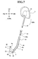
- the pressure receiving member 4 is made of such a rigid body as a steel plate and formed in a rectangular shape extending in left and right directions. In an sectional configuration, as shown in Fig. 4, the pressure receiving member 4 is formed in an almost U-shape with a plane central portion 4a supported with a turned-back portion 10 (having flat faces at the front and rear sides) of an armature pipe 7 (described later) serving as a supporting member, plane first side portions 4c positioned at the front side FR from the central portion 4a via first stepped portions 4b formed in an inclined manner so as not to interfere with flanges 29a formed so as to project ahead of backboard trim brackets 29 respectively supported on the side frames 2b, and flange-shaped second side portions 4e positioned on the front side via second stepped portions 4d formed in an inclined manner so as not to interfere with flanges 2ba formed so as to project ahead of backboard trim brackets 29, respectively.
- the pressure receiving member 4 is spaced from a back face of the pad.
- the cross-sectional shape of the pressure receiving member 4 is formed in a configuration where the pressure receiving member 4 does not interfere with the side frames 2b which are both side portions of the seatback frame 2 and the backboard trim brackets 29, when it is moved at a rearmost position by pressure from a back 30a of a vehicle occupant 30, as shown in Fig. 4.
- an inclination portion 9 formed in a standing manner so as to be opposed to the headrest 3 is provided at the central portion 4a of the pressure receiving member 4, particularly at a portion thereof positioned between holding portions 8 of the armature pipe 7 serving as a supporting member.
- the turned-back portion 10 of the armature pipe 7 having front and back faces formed in a plane shape is fixed to a central portion of the pressure receiving member 4 by gas welding.
- a protector 31 made of synthetic resin and formed so as to cover a whole back face of the pressure receiving member 4 is disposed on a back face side of the pressure receiving member 4 so as to be spaced from the pressure receiving member 4.
- Clips 31 a of the protector 31 are engaged with edges of openings (not shown) formed in the pressure receiving member 4 so that the protector 31 is supported to the pressure receiving member 4.
- the protector 31 is structured so as to bear a load from the rear side RR of the pressure receiving member 4, for example a load imparting by kicking of a rear seat occupant on a back side face of a front seat or his/her own seat or the like.
- the protector 31 is flanged at its upper portion towards the pressure receiving member 4, it generally extends along the pressure receiving member 4, and it is formed at a lower end portion in a curved manner.
- a second frame 28 bridging shoulder portions of the upper frame 2a is fixed at a lower side of the upper frame 2a by welding.
- a holder bracket 12 is disposed at a central portion of the second frame 28, and both end portions 12a of the holder bracket 12 is supported thereat by welding.
- Armature holders 11 are respectively disposed insides supporting portions 12b positioned so as to be spaced from the central portion of the holder bracket 12, each supporting portion 12b being formed in a U-shaped sectional configuration so as to bulge to the front side. Since the armature holders 11 are respectively supported to upper end portions of the holding portions 8 of the armature pipe 7, the holding portions 8 are supported by the supporting portions 12b of the holder bracket 12 through the armature holders 11.
- the armature pipe 7 is formed in an almost U-shaped configuration by the holding portions 8 extending vertically and positioned side by side, as viewed from the front, and the turned-back portion 10 formed so as to connect lower end portions of the holding portions 8 to each other.
- the holding portions 8 are arranged at least inside the shoulder points S1, S2 of AFO 5% tile mannequin (dummy). Such an arrangement means that the holding portions 8 are positioned inside the shoulder points S1, S2 of almost all occupants 30 having a normal adult physique. Therefore, even when a load from the front side of the seatback frame 2 acts on the occupant 30 due to a rear end collision of his/her own automobile, his/her shoulders do not interfere with the holding portions 8.
- the holding portions 8 are formed to be bent towards the pressure receiving member 4 side such that the pressure receiving member 4 is positioned ahead of the holding portions 8.
- the bent portions 8a are formed at portions of the holding portions 8 which are near to stays 13 of the headrest 3 but do not interfere with the stays 13.
- An inner face of each bent portion 8a has a radius of 20 mm.
- the stays 13 of the headrest 3 are supported slidably in a vertical direction in the holding portions 8 via the synthetic resin-made armature holders 11.
- Headrest holders 14 made of synthetic resin and allowing vertical position adjustment of the stays 13 are held at upper end portions of the holding portions 8.
- Reference numeral 14a denotes an engaging portion of the headrest holders 14 and 15 denotes a frame of the headrest 3.
- An S-shaped spring 16 is supported at its both ends to the side frames 2b via hooks 17, and it is arranged at a position below the pressure receiving member 4.
- the holding portions 8 are respectively formed at their rear faces with opening portions 19, as shown in Figs. 2 and 3.
- a tool as a screw driver is inserted to each opening portion 19, the engaging portion 14a of the headrest holder 14 engaged with the opening portion 19 is pushed to be disengaged from the opening portion 19 so that the holding portion 8 can be pulled out. That is, the headrest holder 14 is allowed to log off.
- First rubber-like stoppers 24 are supported to the upper frames 2a at the rear side RR of the holding portions 8, so that the upper portions of the holding portions 8 are prevented from being pivoted towards the rear side RR beyond this rear side RR position.
- a frame 25 for hooking is hooked to a backboard (not shown), and a second stopper 34 is arranged on one of the holding portions 8.
- the second stopper 34 formed in a wire shape prevent the upper end portions of the holding portions 8 from pivoting towards the front FR beyond the position of the second stopper 34.
- FIG. 1 in an ordinary state where the occupant 30 sits on a seat cushion 27 of a seat 27 and his/her back 30a rests on the seatback 1, there is a slight clearance A1 between a head 30b of the occupant 30 and the headrest 3, and there is also a slight clearance B1 between the back 30a of the occupant 30 and the pressure receiving member 4.
- a pad and/or an outer skin (not shown) is interposed between the back 30a of the occupant 30 and the pressure receiving member 4 and a load from the occupant 30 is not transmitted to the pressure receiving member 4.
- the pressure receiving member 4 is formed of a rigid body, the sectional configuration thereof is formed in the almost U-shape, and it is spaced from the back face of the pad, the existing feeling of the pressure receiving member 4 is not given to the occupant 30 via the pad until a load in the rear side RR from the occupant 30 occurs. Namely, foreign feeling is not given to the occupant 30 from the pressure receiving member 4.
- the protector 31 bearing the pressure receiving member 4 against a load from the rear side RR is disposed on the rear face side of the pressure receiving member 4 so as to be spaced from the pressure receiving member 4, the pressure receiving member 4 is not moved towards the front side FR, even when a load is generated by a rear seat occupant from the rear side RR. Namely, an occupant sitting on his/her own seat can be secured much safely.
- the holding portions 8 of the armature pipe 7 of the headrest 3 are prevented from projecting to the rear side RR. That is, the safety of the rear seat occupant is further secured.
- the protector 31 Since the protector 31 is held by the pressure receiving member 4, a clearance between the protector 31 and the pressure receiving member 4 has been given, so that tuning for a load acting from the rear side RR can easily be performed. That is, the clearance between the protector 31 and the pressure receiving member 4 can be made larger or smaller on the basis of a load value.
- the protector 31 has a longitudinal sectional configuration approximately conforming to the pressure receiving member 4, and it is formed at its lower end portion in a curved face. Therefore, even when the lower end portions of holding portions 8 of the armature pipe 7 of the headrest 3 project towards the rear side RR, a safety of a rear seat occupant is maintained higher, as the protector 31 has the curved face at the lower end portion.
- a loading point of the pad disposed a position opposed to the holding portions 8 of the armature pipe 7 regarding movement where the holding portions 8 tend to rotate to move to the upper side UP against the load acting upon the rear side RR is at least the shoulder point S1, S2 regarding the AFO 5% tile dummy, the pad or the like is prevented from biting in the holder portions 8 of the armature pipe 7. Accordingly, the holding portions 8 are not prevented moving upwardly due to rotation thereof, so that a sufficient operation amount of the headrest 3 can be secured.
- the pressure receiving member 4 is formed of a rigid body, the load acting in the rear side RR from the occupant 30 is securely transmitted to the holding portions 8. Namely, since the headrest 3 is moved immediately after the load is imparted on the pressure receiving member 4, thereby eliminate a timing loss. Also, the movement amount of the pressure receiving member 4 is increased.
- the operation links 6 supporting the pressure receiving member 4 are biased to be rotated about the bolts 20 so that the other end portions 6b of the operation links 6 are moved from positions shown in Fig. 1 to positions shown in Fig. 6, so that the other end portions 6b of the operation links 6 are rotated about the bolts 20 to the upper side UP and the rear side RR directions.
- the lower end portion, i.e., the turned-back portion, of the armature pipe 7 are moved to the upper side UP and the rear side RR.
- the headrest holders 14 together with the upper end portions of the armature pipe 7, i.e., the upper end portions 8b of the holding portions 8 are moved to the upper side UP and the front side FR.
- the stays 13 of the headrest 3 are also moved to the upper side UP and the front side FR.
- the holding portions 8 and the stays 13 are rotated together about the holder bracket 12.
- the headrest 3 supported by the stays 13 are brought into contact with the head 30b of the occupant 30, as shown in Fig. 5.
- the headrest 3 appears to bite into the head 30b of the occupant 30.
- the headrest 3 is recessed at its central portion and the head 30b of the occupant 30 is formed in a circular shape in cross-sectional configuration, as is well known, the headrest 3 does not bite into the head 30b.
- the upper half of the occupant 30 is moved to the rear side RR so that the head 30b of the occupant 30 behaves to remain at its original position, but the head 30b is securely held by the movement of the headrest 3.
- the inclination portion 9 rising up to the rear side RR is formed at the upper edge of the pressure receiving member 4, the inclination face 9 of the pressure receiving member 4 can smoothly be moved along the rear face of the pad. In other words, it is hard for the pressure receiving member 4 to bite into the pad.
- the cross-sectional configuration of the pressure receiving member 4 is formed so as not to interfere with the side frames 2b which are the side portions of the seatback frame 2 and the backboard trim brackets 29 at a final position where the pressure receiving member 4 has been moved by pressure of the back 30a of the occupant 30.
- the pressure receiving member 4 does not interfere with the side frames 2b which are the side portions of the seatback frame 2 when the pressure receiving member 4 is moved to the rear side RR.
- each headrest holder 14 is allowed to log off.
- the headrest 3 can be caused to appropriately conform to the position of the head 30b of the occupant 30.
- the pressure receiving member 4 since the springs 18 biasing the pressure receiving member 4 to the front side FR are interposed between the operation links 6 and the side frames 2b of the seatback frame 2, the pressure receiving member 4 is positioned at the front side FR by the springs 18 in a state where pressing force in the rear side RR direction from the back 30a of the occupant 30 is not imparted to the pressure receiving portion 4. That is, since the headrest 3 supported on the upper ends of the holding portions 8 of the armature pipe 7 supporting the pressure receiving member 4 at the lower end is moved at the rear side RR position owing to a seesaw principle, a comfortability of the occupant 30 is not injured in an occupant compartment of the automobile.
- the armature pipe 7 is not limited to this embodiment where it is formed in a U-shape with the holding portions 8 and the turned-back portion 10.
- the armature pipe 7 may be structured such that the turned-back portion 10 is not provided and the lower end portions of the holding portions 8 are directly supported to the pressure receiving member 4 by welding.
- the operation has been explained such that the head 30b of the occupant 30 is securely held by the movement of the headrest 3.
- the above explanation of the operation includes a case where the movement of the headrest 3 and the movement of the seatback 1 are relative to each other, and the headrest 3 is not moved relative to the head 30b of the occupant to remain at its position even when the seatback 3 is moved to the rear side RR by the back 30a of the occupant 30 so that the head 30b of the occupant 30 is protected.
- the armature pipe 7 serving as the supporting member is disposed at least inside the shoulder points S1, S2 of the AFO 5% tile dummy or the occupant in a front view. Therefore, since the shoulder points of the occupant correspond to at least the shoulder points of the AFO 5% tile dummy even when the pad is moved to the rear side by the load given in the rear side by the occupant, the armature pipe 7 is prevented from biting into the pad. For this reason, the headrest 3 is not prevented from rising up according to rotation of the armature pipe 7, and the operation amount of the headrest 3 can sufficiently be secured.
- the pressure receiving member 4 is made of a rigid body, the load acting in the rear side direction by the occupant is securely transmitted to the pressure receiving member 4. Namely, as the pressure receiving member 4 is moved immediately when a load acts on the pressure receiving member 4 by the movement of the headrest, a timing loss does not occur. Also, the movement amount of the pressure receiving member 4 is increased.
- the armature pipe 7 is formed in a configuration where it is bent towards the pressure receiving member 4 side, the pressure receiving member 4 does not project to the rear side when it is moved to the rear side.
- the headrest holders 14 supporting the headrest 3 can easily be detached.
- the pressure receiving member 4 is made of a rigid body, the cross-sectional configuration thereof is formed in a U-shape, and the pressure receiving member 4 is spaced from the rear face of the pad, an existence feeling of the pressure receiving member 4 is not given to the occupant until a load acting in the rear side direction is produced by the occupant. Namely, the pressure receiving member 4 does not give a foreign feeling to the occupant.
- the pressure receiving member bearing the load is made of the rigid body, no rubbing noises is not only generated between the pad and the pressure receiving member but also the load acting in the rear side direction by the back of the occupant is securely transmitted to the headrest 3 when the pad is pressed to be moved to the rear side. That is, the headrest 3 is moved immediately after the load is imparted on the pressure receiving member 4, thereby eliminating a timing loss. In addition thereto, the movement amount of the pressure receiving member 4 is increased.
- the cross-sectional configuration of the pressure receiving member 4 is formed so as not to interfere with the side frames 2b of the seatback frame at a final position where the pressure receiving member 4 has been moved by pressure of the back of the occupant, the pressure receiving member 4 does not interfere with the side frames 2b when it is moved to the rear side.
- the inclination portion 9 slidable on the face of the pad is formed at the upper end portion of the pressure receiving member 4, i.e., the end portion opposed to the headrest 3, a smooth slide of the pressure receiving member 4 on the pad is secured.
- a second embodiment shown in Figs 6 to 8 has the almost same structure as the first embodiment. Same elements are given same reference characters, and detail explanation to them is omitted.
- FIG. 8 there is the headrest shown with a double dotted line and indicated by reference numeral 3, and the headrest 3 shown with the double dotted line shows a position of the headrest 3 in a case where it is not moved. In such a case, the head 30b of the occupant 30 is moved as shown with a fine double dotted line.
Landscapes
- Engineering & Computer Science (AREA)
- Aviation & Aerospace Engineering (AREA)
- Transportation (AREA)
- Mechanical Engineering (AREA)
- Seats For Vehicles (AREA)
Description
- The present invention relates to a seatback for an automobile according to the preamble part of
independent claim 1. - As disclosed in WO 98/09838, a conventional seatback for an automobile comprises at least a seatback frame, supporting means supported rotatably in forward and rearward direction at an upper end portion of the seatback frame, a headrest supported movably in a vertical direction at an upper end portion of the supporting means via a stay, a pressure receiving member supported at a lower end portion of the supporting means and receiving pressure from the back of a vehicle occupant, operating link rotatably pivoted to the seatback frame and the pressure receiving member, and a pad disposed ahead of the pressure receiving member.
- Then, since the headrest instantaneously approaches to the head of an occupant in his/her automobile even when the seatback is flexed rearwardly by reaction load of the occupant at a time when his/her automobile is collided with another vehicle, the head of the occupant is securely received on the headrest, thereby protecting the cervical portion of the occupant.
- Furthermore, EP 0 627 340 A1 discloses a headrest arrangement comprising a headrest cushion with two posts, wherein the two posts are pivotally attached to a seatback frame along a pivotal axis and connected to impact means adapted to pivot forwardly the headrest cushion towards a head of a seat occupant when a pressure has been applied to the impact means.
- In such a technique, however, there is a drawback that, when a horizontal portion of the supporting means positioned on the pressure receiving member is pivoted about a upper frame portion of the seatback frame as a pivoting fulcrum, the horizontal portion may interfere with a shoulder of the occupant. That is, as described above, there is a drawback that the supporting means is not rotated so that the headrest may be prevented from approaching to the head of the occupant.
- Also, there is a drawback that since the pressure receiving member is made of cloth, it is flexed, so that a rearward load of the occupant may not be transmitted securely to the pressure receiving member, which results in delay of movement and reduction of an operation amount of the headrest. Such drawbacks are required to be improved.
- Furthermore, in these conventional arts, there is a drawback that, since the pressure receiving member is made of cloth, rubbing noises may occur between the cloth and the pad, which is required to be improved for comfortability in the vehicle.
- Also, there is a drawback that, as the pressure receiving member is made of cloth, a flexing amount thereof is increased so that rearward load of the occupant may not be securely transmitted to the pressure receiving member, which results in delay of movement and reduction of an operation amount of the headrest. Such drawbacks are required to be improved.
- It is an objective of the present invention to improve a seatback for an automobile as indicated above so as to prevent a pad from biting a supporting member of a headrest, even when a rearward load from an occupant acts on a pressure receiving member, so that an operation amount of the headrest can be secured.
- According to the present invention this objective is solved by a seatback for an automobile comprising a headrest; a seatback frame; a supporting member kept by the seatback frame, wherein the supporting member supports the headrest to be swung, and a pressure receiving member formed of a rigid body and being supported by the supporting member, wherein the pressure receiving member is adapted to swing the supporting member via receiving a predetermined pressure, comprises a cross-sectional configuration formed in an almost U-shape, and is spaced from a back face of a pad arranged in front of the pressure receiving member.
- Preferably, the pressure receiving member has a cross-sectional configuration formed not to interfere with a side portion of the seatback frame at a final position where the pressure receiving member has been moved by a predetermined pressure.
- Preferably, the pressure receiving member has a cross-sectional configuration having a step portion in an inclined manner.
- Preferably, the pressure receiving member is formed at an end opposed to the headrest with an inclination portion to slide a pad arranged on an occupant side.
- Preferably, an operation mechanism is adapted to move in a direction of the pressure, wherein the pressure receiving member is adapted to be restored in an original position by the operation mechanism.
- Preferably, the operation mechanism comprises an operation link connected with the pressure receiving member and an elastic member adapted to restore the pressure receiving member in the original position.
- Preferably, the supporting member bends to the pressure receiving member.
- Preferably, a holder is provided to fit in the supporting member and to keep the headrest; and a lock mechanism is arranged on one side of the supporting member opposite to the pressure receiving member, wherein the lock mechanism is provided to lock the headrest and the holder.
- Further preferred embodiments of the present invention are laid down in the further subclaims.
- In the following, the present invention is explained in greater detail by means of several embodiments thereof in conjunction with the accompanying drawings, wherein:
- Fig. 1 is a side view showing a seatback according to the first embodiment of the present invention;
- Fig. 2 is a perspective view showing a main portion of the seatback shown in Fig. 1;
- Fig. 3 is an exploded perspective view of a main portion of the seatback shown in Fig. 1;
- Fig. 4 is a side view taken along tine IV-IV in Fig. 1;
- Fig. 5 is a cross section showing an operation of the embodiment shown in Fig. 1 put in a used state; and
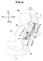
- Fig. 6 is a side view showing the seatback according to the second embodiment of the invention;
- Fig. 7 is a cross section showing a relationship among a headrest, an armature pipe, a pressure receiving member, and an operation shown in Fig. 6;
- Fig. 8 is a side view showing an operation of the embodiment shown in Fig. 6 put in a used state.
-
- A preferred embodiment of the present invention will be explained below with reference to the drawings. In the figures, FR indicates a front side, RR indicates a rear side, UP indicates an upper side and LWR indicates a lower side.
- Figs. 1 to 5 show an embodiment of the present invention, where
reference numeral 1 denotes a seatback for an automobile and 3 denotes a headrest. - The
seatback 1 is composed of at least aseatback frame 2, pads (not shown) formed of polyurethane foam and disposed at a front side and a rear side of theseatback frame 2, and an outer skin made of cloth for covering the pads or the like. - The
seatback frame 2 comprises anupper frame 2a formed in an inverse U-shaped configuration where its one leg portion is long and the other leg portion is short (for securing a space for attaching an airbag apparatus (not shown)), left and sidesymmetrical side frames 2b disposed at positions suspended from left and right end portions of theupper frame 2a and an underframe 2c bridged between lower end potions of theside frames 2b. -
Brackets 5, each being formed of a steel plate in a plate shape, are respectively on theside frames 2b. Oneend portions 6a ofoperation links 6 are respectively supported rotatably in front and rear directions at thebrackets 5 throughbolts 20 andbushes 21.End portions 6a of apressure receiving member 4 described later are rotatably supported to theother end portions 6b of theoperation links 6 viarivets 22 andbushes 21. -
Coil springs 18 serving as biasing means are disposed betweenspring hooks 23 of theside frames 2b and theoperation links 6, and they always bias theother end portions 6b of theoperation links 6 in the front direction FR. - The
pressure receiving member 4 is made of such a rigid body as a steel plate and formed in a rectangular shape extending in left and right directions. In an sectional configuration, as shown in Fig. 4, thepressure receiving member 4 is formed in an almost U-shape with a planecentral portion 4a supported with a turned-back portion 10 (having flat faces at the front and rear sides) of an armature pipe 7 (described later) serving as a supporting member, planefirst side portions 4c positioned at the front side FR from thecentral portion 4a via first steppedportions 4b formed in an inclined manner so as not to interfere withflanges 29a formed so as to project ahead ofbackboard trim brackets 29 respectively supported on theside frames 2b, and flange-shapedsecond side portions 4e positioned on the front side via second steppedportions 4d formed in an inclined manner so as not to interfere with flanges 2ba formed so as to project ahead ofbackboard trim brackets 29, respectively. Thepressure receiving member 4 is spaced from a back face of the pad. - Namely, the cross-sectional shape of the
pressure receiving member 4 is formed in a configuration where thepressure receiving member 4 does not interfere with theside frames 2b which are both side portions of theseatback frame 2 and thebackboard trim brackets 29, when it is moved at a rearmost position by pressure from aback 30a of avehicle occupant 30, as shown in Fig. 4. - Also, as shown Figs. 2 and 3, an
inclination portion 9 formed in a standing manner so as to be opposed to theheadrest 3 is provided at thecentral portion 4a of thepressure receiving member 4, particularly at a portion thereof positioned between holdingportions 8 of thearmature pipe 7 serving as a supporting member. - The turned-
back portion 10 of thearmature pipe 7 having front and back faces formed in a plane shape is fixed to a central portion of thepressure receiving member 4 by gas welding. - A
protector 31 made of synthetic resin and formed so as to cover a whole back face of thepressure receiving member 4 is disposed on a back face side of thepressure receiving member 4 so as to be spaced from thepressure receiving member 4.Clips 31 a of theprotector 31 are engaged with edges of openings (not shown) formed in thepressure receiving member 4 so that theprotector 31 is supported to thepressure receiving member 4. Theprotector 31 is structured so as to bear a load from the rear side RR of thepressure receiving member 4, for example a load imparting by kicking of a rear seat occupant on a back side face of a front seat or his/her own seat or the like. Also, in a vertical section of theprotector 31, theprotector 31 is flanged at its upper portion towards thepressure receiving member 4, it generally extends along thepressure receiving member 4, and it is formed at a lower end portion in a curved manner. - As shown in Fig. 3, a
second frame 28 bridging shoulder portions of theupper frame 2a is fixed at a lower side of theupper frame 2a by welding. Aholder bracket 12 is disposed at a central portion of thesecond frame 28, and bothend portions 12a of theholder bracket 12 is supported thereat by welding.Armature holders 11 are respectively disposedinsides supporting portions 12b positioned so as to be spaced from the central portion of theholder bracket 12, each supportingportion 12b being formed in a U-shaped sectional configuration so as to bulge to the front side. Since thearmature holders 11 are respectively supported to upper end portions of theholding portions 8 of thearmature pipe 7, theholding portions 8 are supported by the supportingportions 12b of theholder bracket 12 through thearmature holders 11. - The
armature pipe 7 is formed in an almost U-shaped configuration by theholding portions 8 extending vertically and positioned side by side, as viewed from the front, and the turned-back portion 10 formed so as to connect lower end portions of theholding portions 8 to each other. - As shown in Fig. 2, the
holding portions 8 are arranged at least inside the shoulder points S1, S2 ofAFO 5% tile mannequin (dummy). Such an arrangement means that theholding portions 8 are positioned inside the shoulder points S1, S2 of almost alloccupants 30 having a normal adult physique. Therefore, even when a load from the front side of theseatback frame 2 acts on theoccupant 30 due to a rear end collision of his/her own automobile, his/her shoulders do not interfere with theholding portions 8. - Also, as shown in Figs. 2 and 3, the
holding portions 8 are formed to be bent towards thepressure receiving member 4 side such that thepressure receiving member 4 is positioned ahead of theholding portions 8. Thebent portions 8a are formed at portions of theholding portions 8 which are near to stays 13 of theheadrest 3 but do not interfere with thestays 13. An inner face of eachbent portion 8a has a radius of 20 mm. - Furthermore, as mentioned above, the
stays 13 of theheadrest 3 are supported slidably in a vertical direction in theholding portions 8 via the synthetic resin-madearmature holders 11.Headrest holders 14 made of synthetic resin and allowing vertical position adjustment of thestays 13 are held at upper end portions of theholding portions 8.Reference numeral 14a denotes an engaging portion of theheadrest holders headrest 3. - An S-
shaped spring 16 is supported at its both ends to theside frames 2b viahooks 17, and it is arranged at a position below thepressure receiving member 4. - The holding
portions 8 are respectively formed at their rear faces with openingportions 19, as shown in Figs. 2 and 3. When such a tool as a screw driver is inserted to each openingportion 19, the engagingportion 14a of theheadrest holder 14 engaged with the openingportion 19 is pushed to be disengaged from the openingportion 19 so that the holdingportion 8 can be pulled out. That is, theheadrest holder 14 is allowed to log off. - First rubber-
like stoppers 24 are supported to theupper frames 2a at the rear side RR of the holdingportions 8, so that the upper portions of the holdingportions 8 are prevented from being pivoted towards the rear side RR beyond this rear side RR position. Aframe 25 for hooking is hooked to a backboard (not shown), and asecond stopper 34 is arranged on one of the holdingportions 8. Thesecond stopper 34 formed in a wire shape prevent the upper end portions of the holdingportions 8 from pivoting towards the front FR beyond the position of thesecond stopper 34. - Next, operation of the embodiment will be explained. As shown in Fig. 1, in an ordinary state where the
occupant 30 sits on aseat cushion 27 of aseat 27 and his/herback 30a rests on theseatback 1, there is a slight clearance A1 between a head 30b of theoccupant 30 and theheadrest 3, and there is also a slight clearance B1 between the back 30a of theoccupant 30 and thepressure receiving member 4. However, a pad and/or an outer skin (not shown) is interposed between the back 30a of theoccupant 30 and thepressure receiving member 4 and a load from theoccupant 30 is not transmitted to thepressure receiving member 4. - In this state, since the
pressure receiving member 4 is formed of a rigid body, the sectional configuration thereof is formed in the almost U-shape, and it is spaced from the back face of the pad, the existing feeling of thepressure receiving member 4 is not given to theoccupant 30 via the pad until a load in the rear side RR from theoccupant 30 occurs. Namely, foreign feeling is not given to theoccupant 30 from thepressure receiving member 4. - Since the
protector 31 bearing thepressure receiving member 4 against a load from the rear side RR is disposed on the rear face side of thepressure receiving member 4 so as to be spaced from thepressure receiving member 4, thepressure receiving member 4 is not moved towards the front side FR, even when a load is generated by a rear seat occupant from the rear side RR. Namely, an occupant sitting on his/her own seat can be secured much safely. - Also, even when the
headrest 3 is moved towards the front side FR, i.e., thepressure receiving member 4 is moved towards the rear side RR, the holdingportions 8 of thearmature pipe 7 of theheadrest 3 are prevented from projecting to the rear side RR. That is, the safety of the rear seat occupant is further secured. - Since the
protector 31 is held by thepressure receiving member 4, a clearance between theprotector 31 and thepressure receiving member 4 has been given, so that tuning for a load acting from the rear side RR can easily be performed. That is, the clearance between theprotector 31 and thepressure receiving member 4 can be made larger or smaller on the basis of a load value. - The
protector 31 has a longitudinal sectional configuration approximately conforming to thepressure receiving member 4, and it is formed at its lower end portion in a curved face. Therefore, even when the lower end portions of holdingportions 8 of thearmature pipe 7 of theheadrest 3 project towards the rear side RR, a safety of a rear seat occupant is maintained higher, as theprotector 31 has the curved face at the lower end portion. - In this state, when an automobile of the
occupant 30 is collided with another vehicle from behind and theoccupant 30 sitting on his/her seat is pressed towards the rear side RR due to a secondary collision so that the pad or the like is moved, thepressure receiving member 4 is pressed to the rear side RR by the back 30a of theoccupant 30 through the pad or the like. - At this time, even when the pad or the like is moved to the rear side RR by a load acting in the rear side RR direction due to the
occupant 30, as thepressure receiving member 4 receiving the load is a rigid body, rubbing noises are not only prevented from being generated between thepressure receiving member 4 and the pad but also the load acting in the rear side RR direction due to the back 30a of theoccupant 30 is securely transmitted to theheadrest 3. That is, theheadrest 3 is moved immediately after the load is imparted on thepressure receiving member 4, thereby eliminating a timing loss. In addition thereto, the movement amount of thepressure receiving member 4 is increased. - Since a loading point of the pad disposed a position opposed to the holding
portions 8 of thearmature pipe 7 regarding movement where the holdingportions 8 tend to rotate to move to the upper side UP against the load acting upon the rear side RR is at least the shoulder point S1, S2 regarding theAFO 5% tile dummy, the pad or the like is prevented from biting in theholder portions 8 of thearmature pipe 7. Accordingly, the holdingportions 8 are not prevented moving upwardly due to rotation thereof, so that a sufficient operation amount of theheadrest 3 can be secured. - Also, the
pressure receiving member 4 is formed of a rigid body, the load acting in the rear side RR from theoccupant 30 is securely transmitted to the holdingportions 8. Namely, since theheadrest 3 is moved immediately after the load is imparted on thepressure receiving member 4, thereby eliminate a timing loss. Also, the movement amount of thepressure receiving member 4 is increased. - The operation links 6 supporting the
pressure receiving member 4 are biased to be rotated about thebolts 20 so that theother end portions 6b of the operation links 6 are moved from positions shown in Fig. 1 to positions shown in Fig. 6, so that theother end portions 6b of the operation links 6 are rotated about thebolts 20 to the upper side UP and the rear side RR directions. - Thus, when the
other end portions 6b of the operation links 6 are rotated to the upper side UP and the rear side RR, the lower end portion, i.e., the turned-back portion, of thearmature pipe 7 are moved to the upper side UP and the rear side RR. According to the movement, theheadrest holders 14 together with the upper end portions of thearmature pipe 7, i.e., the upper end portions 8b of the holdingportions 8, are moved to the upper side UP and the front side FR. According to this movement, thestays 13 of theheadrest 3 are also moved to the upper side UP and the front side FR. - Accordingly, the holding
portions 8 and thestays 13 are rotated together about theholder bracket 12. Theheadrest 3 supported by thestays 13 are brought into contact with thehead 30b of theoccupant 30, as shown in Fig. 5. In Fig. 5, theheadrest 3 appears to bite into thehead 30b of theoccupant 30. However, since theheadrest 3 is recessed at its central portion and thehead 30b of theoccupant 30 is formed in a circular shape in cross-sectional configuration, as is well known, theheadrest 3 does not bite into thehead 30b. - In this manner, the upper half of the
occupant 30 is moved to the rear side RR so that thehead 30b of theoccupant 30 behaves to remain at its original position, but thehead 30b is securely held by the movement of theheadrest 3. At this time, since theinclination portion 9 rising up to the rear side RR is formed at the upper edge of thepressure receiving member 4, theinclination face 9 of thepressure receiving member 4 can smoothly be moved along the rear face of the pad. In other words, it is hard for thepressure receiving member 4 to bite into the pad. - In this state, the cross-sectional configuration of the
pressure receiving member 4 is formed so as not to interfere with the side frames 2b which are the side portions of theseatback frame 2 and the backboardtrim brackets 29 at a final position where thepressure receiving member 4 has been moved by pressure of the back 30a of theoccupant 30. Thus, as shown in Fig. 4, thepressure receiving member 4 does not interfere with the side frames 2b which are the side portions of theseatback frame 2 when thepressure receiving member 4 is moved to the rear side RR. - In the state, as the holding
portions 8 are each formed in a bent configuration toward the side of thepressure receiving member 4 and the back face of the turned-back 10 is covered with theprotector 31, thepressure receiving member 4 and the turned-back portion 10 do not project to the rear side RR, as shown in Fig. 5, when thepressure receiving member 4 is moved to the rear side RR. - Also, when such a tool as a screw driver is inserted into each opening
portion 19 provided on the back face of each holdingportion 8, the engagingportion 14a of theheadrest holder 14 engaged with the openingportion 19 is disengaged from the openingportion 19, so that eachheadrest holder 14 can be pulled from the holdingportion 8. Namely, eachheadrest holder 14 is allowed to log off. - Furthermore, since the respective stays 13 of the
headrest 3 are supported to theheadrest holders 14 movably in a vertical direction, theheadrest 3 can be caused to appropriately conform to the position of thehead 30b of theoccupant 30. - Also, since the
springs 18 biasing thepressure receiving member 4 to the front side FR are interposed between the operation links 6 and the side frames 2b of theseatback frame 2, thepressure receiving member 4 is positioned at the front side FR by thesprings 18 in a state where pressing force in the rear side RR direction from the back 30a of theoccupant 30 is not imparted to thepressure receiving portion 4. That is, since theheadrest 3 supported on the upper ends of the holdingportions 8 of thearmature pipe 7 supporting thepressure receiving member 4 at the lower end is moved at the rear side RR position owing to a seesaw principle, a comfortability of theoccupant 30 is not injured in an occupant compartment of the automobile. - The
armature pipe 7 is not limited to this embodiment where it is formed in a U-shape with the holdingportions 8 and the turned-back portion 10. For example, thearmature pipe 7 may be structured such that the turned-back portion 10 is not provided and the lower end portions of the holdingportions 8 are directly supported to thepressure receiving member 4 by welding. - In the above embodiment, the operation has been explained such that the
head 30b of theoccupant 30 is securely held by the movement of theheadrest 3. Of course, the above explanation of the operation includes a case where the movement of theheadrest 3 and the movement of theseatback 1 are relative to each other, and theheadrest 3 is not moved relative to thehead 30b of the occupant to remain at its position even when theseatback 3 is moved to the rear side RR by the back 30a of theoccupant 30 so that thehead 30b of theoccupant 30 is protected. - According to the present embodiment, the
armature pipe 7 serving as the supporting member is disposed at least inside the shoulder points S1, S2 of theAFO 5% tile dummy or the occupant in a front view. Therefore, since the shoulder points of the occupant correspond to at least the shoulder points of theAFO 5% tile dummy even when the pad is moved to the rear side by the load given in the rear side by the occupant, thearmature pipe 7 is prevented from biting into the pad. For this reason, theheadrest 3 is not prevented from rising up according to rotation of thearmature pipe 7, and the operation amount of theheadrest 3 can sufficiently be secured. - Also, since the
pressure receiving member 4 is made of a rigid body, the load acting in the rear side direction by the occupant is securely transmitted to thepressure receiving member 4. Namely, as thepressure receiving member 4 is moved immediately when a load acts on thepressure receiving member 4 by the movement of the headrest, a timing loss does not occur. Also, the movement amount of thepressure receiving member 4 is increased. - Furthermore, since the
armature pipe 7 is formed in a configuration where it is bent towards thepressure receiving member 4 side, thepressure receiving member 4 does not project to the rear side when it is moved to the rear side. - Also, when log-off is performed behind the
armature pipe 7, theheadrest holders 14 supporting theheadrest 3 can easily be detached. - Since the
pressure receiving member 4 is made of a rigid body, the cross-sectional configuration thereof is formed in a U-shape, and thepressure receiving member 4 is spaced from the rear face of the pad, an existence feeling of thepressure receiving member 4 is not given to the occupant until a load acting in the rear side direction is produced by the occupant. Namely, thepressure receiving member 4 does not give a foreign feeling to the occupant. - Also, since the pressure receiving member bearing the load is made of the rigid body, no rubbing noises is not only generated between the pad and the pressure receiving member but also the load acting in the rear side direction by the back of the occupant is securely transmitted to the
headrest 3 when the pad is pressed to be moved to the rear side. That is, theheadrest 3 is moved immediately after the load is imparted on thepressure receiving member 4, thereby eliminating a timing loss. In addition thereto, the movement amount of thepressure receiving member 4 is increased. - Also, since the cross-sectional configuration of the
pressure receiving member 4 is formed so as not to interfere with the side frames 2b of the seatback frame at a final position where thepressure receiving member 4 has been moved by pressure of the back of the occupant, thepressure receiving member 4 does not interfere with the side frames 2b when it is moved to the rear side. - Furthermore, since the
inclination portion 9 slidable on the face of the pad is formed at the upper end portion of thepressure receiving member 4, i.e., the end portion opposed to theheadrest 3, a smooth slide of thepressure receiving member 4 on the pad is secured. - A second embodiment shown in Figs 6 to 8 has the almost same structure as the first embodiment. Same elements are given same reference characters, and detail explanation to them is omitted.
- Also, in Fig. 8, there is the headrest shown with a double dotted line and indicated by
reference numeral 3, and theheadrest 3 shown with the double dotted line shows a position of theheadrest 3 in a case where it is not moved. In such a case, thehead 30b of theoccupant 30 is moved as shown with a fine double dotted line.
Claims (8)
- A seatback (1) for an automobile comprising:characterized in that the pressure receiving member (4) comprises a cross-sectional configuration formed in an almost U-shape, wherein the pressure receiving member (4) is spaced from a back face of a pad arranged in front of the pressure receiving member (4).a headrest (3);a seatback frame (2);a supporting member (8,9) kept by the seatback frame (2), wherein the supporting member (8,9) supports the headrest (3) to be swung, anda pressure receiving member (4) formed of a rigid body (4a,4b,4c,4d,4e) and being supported by the supporting member (8,9), wherein the pressure receiving member (4) is adapted to swing the supporting member (8,9) via receiving a predetermined pressure,
- A seatback (1) according to claim 1, characterized in that the pressure receiving member (4) comprises a cross-sectional configuration formed to be interfere-free with a side portion (2b) of the seatback frame (2) at a final position, where the pressure receiving member (4) has been moved by a predetermined pressure.
- A seatback (1) according to claim 1 or 2, characterized in that the pressure receiving member (4) comprises a cross-sectional configuration having a step portion (4b,4d) in an inclined manner.
- A seatback (1) according to one of the claims 1 to 3, characterized in that the pressure receiving member (4) is formed at an end opposed to the headrest (3) with an inclination portion to slide a pad arranged on an occupant side.
- A seatback (1) according to one of the claims 1 to 4, characterized by an operation mechanism (6,18) adapted to move in a direction of the pressure, wherein the pressure receiving member (4) is adapted to be restored in an original position by the operation mechanism (6,18).
- A seatback (1) according to claim 5, characterized in that the operation mechanism (6,18) comprises an operation link (6) connected with the pressure receiving member (4) and an elastic member (18) adapted to restore the pressure receiving member (4) in the original position.
- A seatback (1) according to one of the claims 1 to 6, characterized in that the supporting member (8,9) bends to the pressure receiving member (4).
- A seatback (1) according to one of the claims 1 to 7, characterized by a holder (14) fitted in the supporting member (8,9) and keeping the headrest (3); and a lock mechanism (14a,19) arranged on one side of the supporting member (8,9) opposite to the pressure receiving member (4), wherein the lock mechanism (14a,19) is provided to lock the headrest (3) and the holder (14).
Applications Claiming Priority (4)
| Application Number | Priority Date | Filing Date | Title |
|---|---|---|---|
| JP10243751A JP2000071835A (en) | 1998-08-28 | 1998-08-28 | Seat back for vehicle |
| JP24375198 | 1998-08-28 | ||
| JP24375298A JP3487766B2 (en) | 1998-08-28 | 1998-08-28 | Car seat back |
| JP24375298 | 1998-08-28 |
Publications (2)
| Publication Number | Publication Date |
|---|---|
| EP0995631A1 EP0995631A1 (en) | 2000-04-26 |
| EP0995631B1 true EP0995631B1 (en) | 2004-10-27 |
Family
ID=26536419
Family Applications (1)
| Application Number | Title | Priority Date | Filing Date |
|---|---|---|---|
| EP99116700A Expired - Lifetime EP0995631B1 (en) | 1998-08-28 | 1999-08-26 | Seatback for automobile |
Country Status (3)
| Country | Link |
|---|---|
| US (1) | US6250714B1 (en) |
| EP (1) | EP0995631B1 (en) |
| DE (1) | DE69921421T2 (en) |
Cited By (1)
| Publication number | Priority date | Publication date | Assignee | Title |
|---|---|---|---|---|
| CN106256596A (en) * | 2015-06-17 | 2016-12-28 | 福特全球技术公司 | Drive and passengers weight and height estimation |
Families Citing this family (52)
| Publication number | Priority date | Publication date | Assignee | Title |
|---|---|---|---|---|
| JP3750422B2 (en) * | 1999-06-18 | 2006-03-01 | 日産自動車株式会社 | Vehicle seat |
| US6783177B1 (en) * | 1999-08-23 | 2004-08-31 | Ikeda Bussan Co. Ltd. | Seatback for automobile |
| JP2001253282A (en) * | 2000-03-14 | 2001-09-18 | Johnson Controls Automotive Systems Corp | Seat back for automobile |
| JP4152061B2 (en) * | 2000-05-15 | 2008-09-17 | 日産自動車株式会社 | Vehicle occupant restraint system |
| JP3623441B2 (en) | 2000-10-30 | 2005-02-23 | ジョンソン コントロールズ オートモーティブ システムズ株式会社 | Automotive seat back |
| JP3471741B2 (en) * | 2000-11-08 | 2003-12-02 | 日本発条株式会社 | Headrest device |
| US6938953B2 (en) * | 2001-01-23 | 2005-09-06 | Autoliv Development Ab | Vehicle seat |
| DE10206894B4 (en) * | 2001-02-19 | 2006-09-14 | Lear Corp., Southfield | Active headrest for a vehicle seat |
| JP2003125891A (en) * | 2001-10-22 | 2003-05-07 | Aisin Seiki Co Ltd | Lumber support device |
| DE20217258U1 (en) * | 2002-11-08 | 2004-03-18 | Lear Corporation, Southfield | Headrest moving device |
| US7134716B2 (en) * | 2002-11-27 | 2006-11-14 | Lear Corporation | Headrest seat-back arrangement |
| US6789846B2 (en) * | 2002-12-20 | 2004-09-14 | Lear Corporation | Vehicle seat having a movable head restraint |
| US7097242B2 (en) * | 2003-02-06 | 2006-08-29 | Lear Corporation | Anti-backdriving active head restraint |
| US7077472B2 (en) | 2003-06-05 | 2006-07-18 | Trw Vehicle Safety Systems Inc. | Apparatus with actuatable tether for resisting rearward movement of a backrest portion of a seat |
| US6880891B2 (en) * | 2003-06-23 | 2005-04-19 | Lear Corporation | Head restraint for seat |
| US6749256B1 (en) | 2003-09-08 | 2004-06-15 | Lear Corporation | Vehicle seat having a movable head restraint |
| DE10348939B3 (en) * | 2003-10-18 | 2005-01-27 | Daimlerchrysler Ag | Headrest for vehicle seat has a lever system capable of being decoupled to vary select, movement between the impact element and carrier part |
| DE102004020913B3 (en) * | 2004-04-28 | 2005-09-22 | Johnson Controls Gmbh | Vehicle seat with cover panel |
| JP4836422B2 (en) * | 2004-08-26 | 2011-12-14 | 株式会社デルタツーリング | Sheet |
| DE102004050144B4 (en) * | 2004-10-11 | 2013-09-19 | Volkswagen Ag | Active headrest with decoupled lumbar frame |
| JP4737501B2 (en) | 2004-10-28 | 2011-08-03 | テイ・エス テック株式会社 | Vehicle seat |
| JP4492870B2 (en) * | 2004-12-27 | 2010-06-30 | テイ・エス テック株式会社 | Vehicle seat |
| US7185950B2 (en) * | 2004-12-28 | 2007-03-06 | Fisher Dynamics Corporation | Head restraint system |
| US20060138817A1 (en) * | 2004-12-29 | 2006-06-29 | Gorman Patrick J | Energy absorbing seat recliner assembly |
| WO2006078040A1 (en) * | 2005-01-18 | 2006-07-27 | Nhk Spring Co., Ltd. | Vehicular seat |
| JP4087854B2 (en) * | 2005-01-20 | 2008-05-21 | 株式会社タチエス | Seat back |
| US20060226686A1 (en) * | 2005-03-22 | 2006-10-12 | Shihong Yu | Spinal protection system for automotive seat |
| GB2424363B (en) * | 2005-03-24 | 2008-07-16 | Autoliv Dev | Active headrest with lock mechanism |
| CN101272930B (en) * | 2005-07-22 | 2013-05-22 | 东京座椅技术株式会社 | Linking mechanism for headrest of vehicle seat |
| EP1939033B1 (en) * | 2005-08-30 | 2011-04-20 | TS Tech Co., Ltd. | Vehicle seat and method of assembling vehicle seat |
| JP5007071B2 (en) * | 2006-05-29 | 2012-08-22 | テイ・エス テック株式会社 | Vehicle seat |
| EP2032000A4 (en) * | 2006-06-16 | 2010-05-26 | Schukra North America Ltd | Head rest release mechanism |
| US20080030061A1 (en) * | 2006-08-04 | 2008-02-07 | Srinivas Pejathaya | Multi-position adjustment mechanism |
| KR100794046B1 (en) * | 2006-08-10 | 2008-01-10 | 현대자동차주식회사 | Locking structure of the active headrest |
| US7549699B2 (en) * | 2006-08-21 | 2009-06-23 | Lear Corporation | Moveable back panel for a vehicle seat |
| US20080185900A1 (en) * | 2006-09-28 | 2008-08-07 | Lee Ellen Cheng-Ch | Use of renewable and biodegradable materials for automotive interiors |
| US20080164730A1 (en) * | 2007-01-05 | 2008-07-10 | Ford Global Technologies, Llc | Insert for vehicle seat head restraint |
| US7677659B2 (en) * | 2007-02-06 | 2010-03-16 | Lear Corporation | Active head restraint systems for vehicle seats |
| US7845721B2 (en) * | 2007-02-14 | 2010-12-07 | Inoac Corporation | Headrest |
| JP5276808B2 (en) * | 2007-07-19 | 2013-08-28 | テイ・エス テック株式会社 | Seat back frame and vehicle seat |
| US7850235B2 (en) * | 2007-10-17 | 2010-12-14 | Lear Corporation | Active head restraint system with actuating system for a vehicle seat |
| JP5184861B2 (en) * | 2007-10-24 | 2013-04-17 | 日本テクニカ株式会社 | Headrest device for active headrest |
| US8690238B2 (en) * | 2008-01-14 | 2014-04-08 | Ford Global Technologies, Llc | Active head restraint system for an automotive vehicle seat |
| US7699394B2 (en) * | 2008-05-13 | 2010-04-20 | Lear Corporation | Connections for active head restraint systems for vehicle seats |
| US7758114B2 (en) * | 2008-07-15 | 2010-07-20 | Tachi-S Co. Ltd. | Seat back structure of vehicle seat |
| US8205941B2 (en) * | 2008-07-30 | 2012-06-26 | Trw Vehicle Safety Systems Inc. | Active head restraint for a vehicle seat |
| US8544948B2 (en) * | 2009-01-21 | 2013-10-01 | Ts Tech Co., Ltd. | Vehicle seat |
| EP2390130A1 (en) | 2009-01-21 | 2011-11-30 | TS Tech Co., Ltd. | Vehicle seat |
| US7959224B2 (en) * | 2009-03-17 | 2011-06-14 | Ford Global Technologies, Llc | Active head restraint having multiple horizontal pivot points |
| JP2012030632A (en) * | 2010-07-29 | 2012-02-16 | Toyota Boshoku Corp | Vehicle seat |
| EP2657071B1 (en) | 2010-12-24 | 2018-04-11 | TS Tech Co., Ltd. | Vehicle seat |
| US10059234B2 (en) * | 2016-06-10 | 2018-08-28 | Ford Global Technologies, Llc | Vehicle seatback |
Family Cites Families (9)
| Publication number | Priority date | Publication date | Assignee | Title |
|---|---|---|---|---|
| US5378043A (en) * | 1993-06-01 | 1995-01-03 | General Motors Corporation | Vehicle pivotal headrest |
| US5823619A (en) * | 1996-03-04 | 1998-10-20 | Trw Occupant Restraint Systems Gmbh | Vehicle seat |
| SE510735C2 (en) * | 1996-09-06 | 1999-06-21 | Saab Automobile | Vehicle seat equipped with a headrest |
| GB2318045B (en) * | 1996-10-09 | 2000-08-09 | Delphi Automotive Systems Gmbh | Vehicle seat and headrest arrangement |
| US5884968A (en) * | 1997-01-23 | 1999-03-23 | Lear Corporation | Seat assembly with pneumatically adjustable contour and energy absorption |
| FR2765533B1 (en) * | 1997-07-03 | 1999-09-03 | Faure Bertrand Equipements Sa | VEHICLE SEAT WITH A NECK PROTECTION DEVICE IN THE EVENT OF A REAR IMPACT |
| DE19753540A1 (en) * | 1997-12-03 | 1999-06-10 | Ewald Witte Gmbh & Co Kg | Headrest, especially for motor vehicles |
| US5927804A (en) * | 1998-02-11 | 1999-07-27 | Trw Inc. | Vehicle occupant protection apparatus |
| US5938279A (en) * | 1998-05-01 | 1999-08-17 | Lear Corporation | Dynamic vehicle head restraint assembly |
-
1999
- 1999-08-26 DE DE69921421T patent/DE69921421T2/en not_active Expired - Fee Related
- 1999-08-26 EP EP99116700A patent/EP0995631B1/en not_active Expired - Lifetime
- 1999-08-27 US US09/384,232 patent/US6250714B1/en not_active Expired - Fee Related
Cited By (1)
| Publication number | Priority date | Publication date | Assignee | Title |
|---|---|---|---|---|
| CN106256596A (en) * | 2015-06-17 | 2016-12-28 | 福特全球技术公司 | Drive and passengers weight and height estimation |
Also Published As
| Publication number | Publication date |
|---|---|
| EP0995631A1 (en) | 2000-04-26 |
| US6250714B1 (en) | 2001-06-26 |
| DE69921421T2 (en) | 2005-05-04 |
| DE69921421D1 (en) | 2004-12-02 |
Similar Documents
| Publication | Publication Date | Title |
|---|---|---|
| EP0995631B1 (en) | Seatback for automobile | |
| EP1078811B1 (en) | Seatback for automobile | |
| JP3623441B2 (en) | Automotive seat back | |
| GB2283163A (en) | "Improvements in or relating to a vehicle seat" | |
| WO2002074579A1 (en) | Safety headrest for a motor vehicle | |
| JP2000211412A (en) | Automotive seat back | |
| JP2000201769A (en) | Seat back for automobile | |
| JP2000217660A (en) | Automobile backrest | |
| JP3595692B2 (en) | Car seat back | |
| JP2000201770A (en) | Seat back for automobile | |
| JP2000210157A (en) | Seatback for automobile | |
| JP2001058533A (en) | Seat back for automobile | |
| JP3487766B2 (en) | Car seat back | |
| JP2000236985A (en) | Car seat backrest | |
| JP3522548B2 (en) | Car seat back | |
| JP3578920B2 (en) | Car seat back | |
| JP3542722B2 (en) | Car seat back | |
| JP2000210156A (en) | Seatback for automobile | |
| JP2001039194A (en) | Seat back for automobile | |
| JP2000125980A (en) | Seat back for automobile | |
| JP2000071835A (en) | Seat back for vehicle | |
| JP3522603B2 (en) | Car seat back | |
| JP3595767B2 (en) | Car seat back | |
| JP2000127825A (en) | Seat back for automobile | |
| JP2000125984A (en) | Seat back for automobile |
Legal Events
| Date | Code | Title | Description |
|---|---|---|---|
| PUAI | Public reference made under article 153(3) epc to a published international application that has entered the european phase |
Free format text: ORIGINAL CODE: 0009012 |
|
| 17P | Request for examination filed |
Effective date: 19990826 |
|
| AK | Designated contracting states |
Kind code of ref document: A1 Designated state(s): DE FR GB |
|
| AX | Request for extension of the european patent |
Free format text: AL;LT;LV;MK;RO;SI |
|
| AKX | Designation fees paid |
Free format text: DE FR GB |
|
| 17Q | First examination report despatched |
Effective date: 20030911 |
|
| GRAP | Despatch of communication of intention to grant a patent |
Free format text: ORIGINAL CODE: EPIDOSNIGR1 |
|
| GRAA | (expected) grant |
Free format text: ORIGINAL CODE: 0009210 |
|
| GRAS | Grant fee paid |
Free format text: ORIGINAL CODE: EPIDOSNIGR3 |
|
| AK | Designated contracting states |
Kind code of ref document: B1 Designated state(s): DE FR GB |
|
| REG | Reference to a national code |
Ref country code: GB Ref legal event code: FG4D |
|
| REF | Corresponds to: |
Ref document number: 69921421 Country of ref document: DE Date of ref document: 20041202 Kind code of ref document: P |
|
| PG25 | Lapsed in a contracting state [announced via postgrant information from national office to epo] |
Ref country code: GB Free format text: LAPSE BECAUSE OF NON-PAYMENT OF DUE FEES Effective date: 20050826 |
|
| ET | Fr: translation filed | ||
| PLBE | No opposition filed within time limit |
Free format text: ORIGINAL CODE: 0009261 |
|
| STAA | Information on the status of an ep patent application or granted ep patent |
Free format text: STATUS: NO OPPOSITION FILED WITHIN TIME LIMIT |
|
| 26N | No opposition filed |
Effective date: 20050728 |
|
| PG25 | Lapsed in a contracting state [announced via postgrant information from national office to epo] |
Ref country code: DE Free format text: LAPSE BECAUSE OF NON-PAYMENT OF DUE FEES Effective date: 20060301 |
|
| GBPC | Gb: european patent ceased through non-payment of renewal fee |
Effective date: 20050826 |
|
| PG25 | Lapsed in a contracting state [announced via postgrant information from national office to epo] |
Ref country code: FR Free format text: LAPSE BECAUSE OF NON-PAYMENT OF DUE FEES Effective date: 20060428 |
|
| REG | Reference to a national code |
Ref country code: FR Ref legal event code: ST Effective date: 20060428 |