EP0995402A2 - A surgical trephine - Google Patents
A surgical trephine Download PDFInfo
- Publication number
- EP0995402A2 EP0995402A2 EP99308271A EP99308271A EP0995402A2 EP 0995402 A2 EP0995402 A2 EP 0995402A2 EP 99308271 A EP99308271 A EP 99308271A EP 99308271 A EP99308271 A EP 99308271A EP 0995402 A2 EP0995402 A2 EP 0995402A2
- Authority
- EP
- European Patent Office
- Prior art keywords
- piston
- bore
- trephine
- surgical
- surgical trephine
- Prior art date
- Legal status (The legal status is an assumption and is not a legal conclusion. Google has not performed a legal analysis and makes no representation as to the accuracy of the status listed.)
- Granted
Links
Images

Classifications
-
- A—HUMAN NECESSITIES
- A61—MEDICAL OR VETERINARY SCIENCE; HYGIENE
- A61B—DIAGNOSIS; SURGERY; IDENTIFICATION
- A61B17/00—Surgical instruments, devices or methods, e.g. tourniquets
- A61B17/16—Bone cutting, breaking or removal means other than saws, e.g. Osteoclasts; Drills or chisels for bones; Trepans
- A61B17/1637—Hollow drills or saws producing a curved cut, e.g. cylindrical
Definitions
- This invention relates to a surgical trephine adapted for boring an opening in tamped bone chippings.
- the present invention is intended to provide an instrument which can be used for cutting the required cavity into bone chippings in operations of the kind described above, although it can be used for any cavity in which bone chippings are used and a substantially parallel cavity is required.
- a surgical trephine adapted for boring an opening in tamped bone chippings includes a hollow elongate body portion having an internal bore and the distal end of which has an annular cutting rim, a piston located in said bore with a piston surface facing towards said cutting rim and means for moving the piston in the bore.
- an elongate cavity can be cut in the bone chippings, the debris from the cutting entering the distal end of the internal bore and slowly pushing the piston up the bore away from the distal end.
- the chippings can then be easily dislodged from the bore by displacing the piston.
- the body portion may include an aperture in the wall passing into the bore at a point spaced away from the distal end to facilitate cleaning after operation.
- the action of the surgeon can be back and forth or with a continuous rotation or with an up and down motion in the form of a pile driver.
- an extension or extended portion of the piston projects beyond the proximal end of the body portion and means can be provided for limiting the movement of the piston up said bore and away from the distal end to a position adjacent the proximal end of the aperture.
- the annular cutting rim is provided with cutting teeth although, in certain circumstances, merely a sharpened edge may be required.
- the proximal end of the extended portion of the piston or an extension thereof can be provided with removable means to limit the movement of the piston in a distal direction. These means can be removed so that the device can be completely dismantled for cleaning but when it is in position it locates the piston in the bore and prevents the piston dropping through the main body.
- the hollow elongate body portion is provided with an operating handle which can be in the form of a T-piece.
- the hollow elongate body portion can also be provided with a depth gauge and means can be provided on the extended portion of the piston, or extension thereof, to provide a position indicator.
- the proximal end of the extended portion of the piston, or an extension thereof, can be provided with means for attaching a power source so that the device can be operated by a power device.
- the piston can be provided with means to accept a guide wire so that the trephine can be used as one of a series of operations when carrying out the preparation of the bone for implantation.
- a femur 1 is shown in which the intramedullary canal has been treated to provide a cavity 2 into which a prosthesis with a long stem is intended to be inserted.
- a phantom prosthesis 3 with a long stem 4 is shown which will eventually be removed and replaced by the surgical prosthesis. This technique is described and shown in the Applicants pending European Patent Application No. 95306990.3 (EP 0 705 579).
- EP 0 705 579 European Patent Application No. 95306990.3
- the present invention allows the distal end of the cavity to be completely filled with bone chippings up to a level indicated by reference numeral 6.
- a guide wire 7 is placed in position, usually held by a retaining plug 8, and this guide wire is used, in well known manner, to guide an accurately locate the various components which are used during the operation.
- the guide wire is, of course, placed in position before the bone chippings are inserted.
- a phantom technique is employed the phantom 3 is withdrawn, the cavity within the bone chippings is lined with cement and the surgical prosthesis subsequently inserted with or without the use of a guide wire.
- the present invention provides a trephine which can be used to cut out the tamped and compressed bone fragments beneath the level 6 and comprises a hollow elongate body portion which has an internal bore 11 and the distal end 12 of which has an annular cutting rim 13.
- the cutting rim can be provided with teeth 14, as shown in Figure 5.
- an elongate piston 14 which has an extension 15 which projects from the proximal end 16 of the main body 10.
- the main body 10 is extended by a cross-piece 17 which acts an operating handle.
- the proximal end of the extension 15 is provided with a knurled nut 18 which is shaped to allow easy removal and is adapted to receive an appropriate operating attachment from a power tool. As the nut 18 is screw threaded onto the end of the extension 15 it can be readily removed by hand but it acts as a stop to prevent the piston 14 passing completely through the main body portion 10.
- the distal end of the piston 14 is enlarged at 19 and the diameter of the bore 11 is also enlarged at its distal end to accommodate the enlarged portion 19 is the piston.
- An aperture 20 is provided in the wall of the bore 11 and the enlarged portion of the bore ends at the proximal end of this aperture.
- the piston 14 can move towards the distal end of the bore 11 until it emerges from the distal end thereof. Further movement is however restricted by the stop 18. In the other proximal direction the piston can move up the bore 11 until it reaches the position shown in the drawings and where the enlarged part of the piston 19 meets the thicker wall of the upper part of the bore 11.
- the piston is guided by its wall 21 operating in the narrower part 22 of the bore 11 and the enlarged portion of the piston 19 therefore limits the movement of the piston up the bore and away from the annular cutting rim 13 to a position adjacent the proximal end of the aperture.
- the outer surface of the elongate body portion is provided with a depth gauge in the form of appropriate markings indicated by reference numeral 25 and the piston extension 15 carries a position indicator 26 which indicated when the piston 19 has reached the upper end of the aperture 20.
- the piston 14 and extension 15 are provided with means to accept a guide wire in the form of a guide bore 27.
- the trephine is fed down a guide wire, for example similar to that shown in Figure 1 and indicated by reference numeral 7, and a backwards and forwards or rotary movement is applied by the operating handle 17 to cause the cutting rim 13 to cut into the bone chippings, the chippings which have been cut away passing up the bore 11 and pushing the face 28 of the piston in front of them.
- the precise depth of the trephine within the bone can be seen from the depth gauge 25. Frequent removal of the device will enable the surgeon to see how far the bone chippings have passed up the bore 11 but the position indicator 27 will immediately make him aware if the lower end of the bore 11 has become completely filled.
- the device is now removed from the cavity and the bone chippings can be easily expelled by pushing the piston downwardly so that the chippings are expelled through the opening 20 or through the open distal end. Cutting can now be resumed until the required depth, as indicated on the depth gauge 25, is achieved to thus provide an opening which is suitable to receive the prosthesis, or phantom prosthesis, which is to be inserted.
- the outer diameter of the elongate body portion will be appropriate for the prosthesis with which it is to be used.
- the construction is such that the trephine can be easily dismantled for cleaning. Thus, it is merely necessary to remove the stop 18 so that the piston can slide out of the bore 11. Similarly the operating handle 17 is screw threaded onto the proximal end of the body portion 10 so that it can also be easily removed.
- the construction can be such that a number of body portions of different external diameters can be provided but with a bore of a single diameter so that the piston can be used with other body portions, as can the handle. Alternatively, a series of devices can be provided for different diameters.
- One of the advantages of the piston is that it can be used to clean the bore 11 during use and because of the stops it reduces the possibility of jamming bone chippings in the bore if a surgeon continues to operate the device with the bore full.
Abstract
Description
- This invention relates to a surgical trephine adapted for boring an opening in tamped bone chippings.
- Modern surgical techniques, especially as applied to hip prostheses, sometimes require a prosthetic device with an elongated stem. These devices are used when not only are there problems with the hip joint but there is also the possibility of fracturing in the length of the femur. The addition of a standard length prosthesis stem into such a femur can sometimes create further problems and for this reason a stem of much longer length is employed. The distal portion of such stems is usually parallel because of the extended length and the narrowing of the femur and its intramedullary canal.
- In modern techniques bone chippings can be employed to line the intramedullary canal and these chippings are first tamped into position, for example as described and shown in the Applicants pending European Patent Application No. 95306990.3 (EP 0 705 579). This Application shows a method and apparatus for implanting a prosthesis in which a bone cavity is filled with bone chips which are compressed.
- When such a technique is used for long prosthesis stems there are difficulties in shaping the distal end of the cavity due, not only to the long length, but also to the possibilities of causing further compression of the bone chippings and thus tending to expand the filling and create fractures in the bone structure.
- The present invention is intended to provide an instrument which can be used for cutting the required cavity into bone chippings in operations of the kind described above, although it can be used for any cavity in which bone chippings are used and a substantially parallel cavity is required.
- According to the present invention a surgical trephine adapted for boring an opening in tamped bone chippings includes a hollow elongate body portion having an internal bore and the distal end of which has an annular cutting rim, a piston located in said bore with a piston surface facing towards said cutting rim and means for moving the piston in the bore.
- With this device an elongate cavity can be cut in the bone chippings, the debris from the cutting entering the distal end of the internal bore and slowly pushing the piston up the bore away from the distal end. When the body portion is withdrawn from the cavity, the chippings can then be easily dislodged from the bore by displacing the piston.
- The body portion may include an aperture in the wall passing into the bore at a point spaced away from the distal end to facilitate cleaning after operation.
- The action of the surgeon can be back and forth or with a continuous rotation or with an up and down motion in the form of a pile driver.
- Preferably an extension or extended portion of the piston projects beyond the proximal end of the body portion and means can be provided for limiting the movement of the piston up said bore and away from the distal end to a position adjacent the proximal end of the aperture.
- Preferably the annular cutting rim is provided with cutting teeth although, in certain circumstances, merely a sharpened edge may be required.
- The proximal end of the extended portion of the piston or an extension thereof can be provided with removable means to limit the movement of the piston in a distal direction. These means can be removed so that the device can be completely dismantled for cleaning but when it is in position it locates the piston in the bore and prevents the piston dropping through the main body.
- Preferably the hollow elongate body portion is provided with an operating handle which can be in the form of a T-piece.
- The hollow elongate body portion can also be provided with a depth gauge and means can be provided on the extended portion of the piston, or extension thereof, to provide a position indicator.
- If desired the proximal end of the extended portion of the piston, or an extension thereof, can be provided with means for attaching a power source so that the device can be operated by a power device.
- The piston can be provided with means to accept a guide wire so that the trephine can be used as one of a series of operations when carrying out the preparation of the bone for implantation.
- The invention can be performed in various ways but one embodiment will now be described by way of example and with reference to the accompanying drawings, in which :
- Figure 1 is a diagrammatic illustration of a typical phantom for a prosthesis with a long stem impacted into bone chippings in a femur;
- Figure 2 is a side elevation of a surgical trephine according to the present invention;
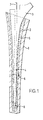
- Figure 3 is a cross-sectional front elevation of the device shown in Figure 2 on the lines III-III;
- Figure 4 is an isometric view of the trephine according to the invention; and,
- Figure 5 is an enlarged view of the teeth used on the annular cutting rim of the device according to the invention.
-
- In Figure 1 a femur 1 is shown in which the intramedullary canal has been treated to provide a
cavity 2 into which a prosthesis with a long stem is intended to be inserted. In Figure 1 a phantom prosthesis 3 with along stem 4 is shown which will eventually be removed and replaced by the surgical prosthesis. This technique is described and shown in the Applicants pending European Patent Application No. 95306990.3 (EP 0 705 579). When thecavity 2 has been prepared it is filled withbone chippings 5 and these are tamped and compressed. When a long stem is to be used however there are difficulties in tamping the bone chippings against the sides of thecavity 2 by the usual techniques but the present invention allows the distal end of the cavity to be completely filled with bone chippings up to a level indicated byreference numeral 6. - When the bone cavity is being prepared a guide wire 7 is placed in position, usually held by a
retaining plug 8, and this guide wire is used, in well known manner, to guide an accurately locate the various components which are used during the operation. The guide wire is, of course, placed in position before the bone chippings are inserted. When a phantom technique is employed the phantom 3 is withdrawn, the cavity within the bone chippings is lined with cement and the surgical prosthesis subsequently inserted with or without the use of a guide wire. - The present invention provides a trephine which can be used to cut out the tamped and compressed bone fragments beneath the
level 6 and comprises a hollow elongate body portion which has an internal bore 11 and thedistal end 12 of which has anannular cutting rim 13. The cutting rim can be provided withteeth 14, as shown in Figure 5. - Located in the bore 11 is an
elongate piston 14 which has anextension 15 which projects from theproximal end 16 of themain body 10. In the construction shown in the drawings themain body 10 is extended by across-piece 17 which acts an operating handle. - The proximal end of the
extension 15 is provided with aknurled nut 18 which is shaped to allow easy removal and is adapted to receive an appropriate operating attachment from a power tool. As thenut 18 is screw threaded onto the end of theextension 15 it can be readily removed by hand but it acts as a stop to prevent thepiston 14 passing completely through themain body portion 10. - The distal end of the
piston 14 is enlarged at 19 and the diameter of the bore 11 is also enlarged at its distal end to accommodate the enlargedportion 19 is the piston. Anaperture 20 is provided in the wall of the bore 11 and the enlarged portion of the bore ends at the proximal end of this aperture. Thus, thepiston 14 can move towards the distal end of the bore 11 until it emerges from the distal end thereof. Further movement is however restricted by thestop 18. In the other proximal direction the piston can move up the bore 11 until it reaches the position shown in the drawings and where the enlarged part of thepiston 19 meets the thicker wall of the upper part of the bore 11. At all times the piston is guided by itswall 21 operating in thenarrower part 22 of the bore 11 and the enlarged portion of thepiston 19 therefore limits the movement of the piston up the bore and away from theannular cutting rim 13 to a position adjacent the proximal end of the aperture. - The outer surface of the elongate body portion is provided with a depth gauge in the form of appropriate markings indicated by
reference numeral 25 and thepiston extension 15 carries aposition indicator 26 which indicated when thepiston 19 has reached the upper end of theaperture 20. - The
piston 14 andextension 15 are provided with means to accept a guide wire in the form of a guide bore 27. - In operation the trephine is fed down a guide wire, for example similar to that shown in Figure 1 and indicated by reference numeral 7, and a backwards and forwards or rotary movement is applied by the
operating handle 17 to cause thecutting rim 13 to cut into the bone chippings, the chippings which have been cut away passing up the bore 11 and pushing theface 28 of the piston in front of them. The precise depth of the trephine within the bone can be seen from thedepth gauge 25. Frequent removal of the device will enable the surgeon to see how far the bone chippings have passed up the bore 11 but theposition indicator 27 will immediately make him aware if the lower end of the bore 11 has become completely filled. The device is now removed from the cavity and the bone chippings can be easily expelled by pushing the piston downwardly so that the chippings are expelled through the opening 20 or through the open distal end. Cutting can now be resumed until the required depth, as indicated on thedepth gauge 25, is achieved to thus provide an opening which is suitable to receive the prosthesis, or phantom prosthesis, which is to be inserted. - It will be appreciated that the outer diameter of the elongate body portion will be appropriate for the prosthesis with which it is to be used.
- The construction is such that the trephine can be easily dismantled for cleaning. Thus, it is merely necessary to remove the
stop 18 so that the piston can slide out of the bore 11. Similarly theoperating handle 17 is screw threaded onto the proximal end of thebody portion 10 so that it can also be easily removed. The construction can be such that a number of body portions of different external diameters can be provided but with a bore of a single diameter so that the piston can be used with other body portions, as can the handle. Alternatively, a series of devices can be provided for different diameters. - One of the advantages of the piston is that it can be used to clean the bore 11 during use and because of the stops it reduces the possibility of jamming bone chippings in the bore if a surgeon continues to operate the device with the bore full.
Claims (11)
- A surgical trephine adapted for boring an opening in tamped bone chippings which includes a hollow elongate body portion having an internal bore and the distal end of which has an annular cutting rim, a piston located in said bore with a piston surface facing towards said cutting rim, means for moving the piston in the bore.
- A surgical trephine as claimed in claim 1 in which said body portion includes an aperture in the wall passing into the bore at a point spaced away from the distal end to facilitate cleaning after operation.
- A surgical trephine as claimed in claim 1 or claim 2 in which an extension or extended portion of the piston projects beyond the proximal end of the body portion.
- A surgical trephine as claimed in claim 2 or claim 3 in which means are provided for limiting the movement of the piston up said bore and away from the distal end to a position adjacent the proximal end of said aperture.
- A surgical trephine as claimed in any one of preceding claims 1 to 4 in which said annular cutting rim is provided with cutting teeth.
- A surgical trephine as claimed in any one of preceding claims 3, 4 or 5 in which the proximal end of the extended portion of the piston or an extension thereof is provided with removable means to limit the movement of the piston in a distal direction.
- A surgical trephine as claimed in any one of preceding claims 1 to 6 in which the hollow elongate body portion is provided with an operating handle.
- A surgical trephine as claimed in any one of preceding claims 1 to 7 in which said elongate body portion is provided with a depth gauge.
- A surgical trephine as claimed in any one of preceding claims 1 to 8 in which means are provided on the extended portion of the piston, or extension thereof, to provide a position indicator.
- A surgical trephine as claimed in any one of preceding claims 3 to 9 in which the proximal end of the extended portion of the piston or an extension thereof is provided with means for attaching a power source so that the device can be operated by a power device.
- A surgical trephine as claimed in any one of preceding claims in which the piston is provided with means to accept a guide wire.
Applications Claiming Priority (2)
| Application Number | Priority Date | Filing Date | Title |
|---|---|---|---|
| GB9823305 | 1998-10-23 | ||
| GBGB9823305.9A GB9823305D0 (en) | 1998-10-23 | 1998-10-23 | A surgical trephine |
Publications (3)
| Publication Number | Publication Date |
|---|---|
| EP0995402A2 true EP0995402A2 (en) | 2000-04-26 |
| EP0995402A3 EP0995402A3 (en) | 2000-06-28 |
| EP0995402B1 EP0995402B1 (en) | 2005-03-09 |
Family
ID=10841227
Family Applications (1)
| Application Number | Title | Priority Date | Filing Date |
|---|---|---|---|
| EP99308271A Expired - Lifetime EP0995402B1 (en) | 1998-10-23 | 1999-10-20 | A surgical trephine |
Country Status (7)
| Country | Link |
|---|---|
| US (1) | US6200319B1 (en) |
| EP (1) | EP0995402B1 (en) |
| JP (1) | JP2000139932A (en) |
| AU (1) | AU757866B2 (en) |
| CA (1) | CA2288508A1 (en) |
| DE (1) | DE69924066T2 (en) |
| GB (1) | GB9823305D0 (en) |
Cited By (3)
| Publication number | Priority date | Publication date | Assignee | Title |
|---|---|---|---|---|
| FR2816824A1 (en) * | 2000-11-23 | 2002-05-24 | Michel Kurc | Recuperator trepan for bone has tube driven for rotation and with opening surrounded by teeth at front end |
| US20110288553A1 (en) * | 2008-05-23 | 2011-11-24 | Spine View, Inc. | Method and devices for treating spinal stenosis |
| WO2022153115A1 (en) * | 2021-01-15 | 2022-07-21 | Stefan Eggli | Bone plug insertion instrument |
Families Citing this family (18)
| Publication number | Priority date | Publication date | Assignee | Title |
|---|---|---|---|---|
| US6783533B2 (en) * | 2001-11-21 | 2004-08-31 | Sythes Ag Chur | Attachable/detachable reaming head for surgical reamer |
| US20040119175A1 (en) * | 2002-12-20 | 2004-06-24 | Reed Bryan M. | Apparatus and method for manufacturing intraocular lenses |
| DE20300988U1 (en) * | 2003-01-23 | 2003-04-03 | Stryker Trauma Gmbh | Drilling tool for bone, especially the proximal femur |
| US7517364B2 (en) | 2003-03-31 | 2009-04-14 | Depuy Products, Inc. | Extended articulation orthopaedic implant and associated method |
| US7338498B2 (en) * | 2003-03-31 | 2008-03-04 | Depuy Products, Inc. | Prosthetic implant, trial and associated method |
| US8366713B2 (en) | 2003-03-31 | 2013-02-05 | Depuy Products, Inc. | Arthroplasty instruments and associated method |
| US8545506B2 (en) | 2003-03-31 | 2013-10-01 | DePuy Synthes Products, LLC | Cutting guide for use with an extended articulation orthopaedic implant |
| US20040193278A1 (en) * | 2003-03-31 | 2004-09-30 | Maroney Brian J. | Articulating surface replacement prosthesis |
| US7527631B2 (en) * | 2003-03-31 | 2009-05-05 | Depuy Products, Inc. | Arthroplasty sizing gauge |
| US8105327B2 (en) | 2003-03-31 | 2012-01-31 | Depuy Products, Inc. | Punch, implant and associated method |
| US20060052869A1 (en) * | 2003-06-26 | 2006-03-09 | Reed Bryan M | IOL square edge punch and haptic insertion fixture |
| US7879042B2 (en) * | 2004-03-05 | 2011-02-01 | Depuy Products, Inc. | Surface replacement extractor device and associated method |
| DE102005006316A1 (en) * | 2005-02-11 | 2006-08-24 | Nowakowski, Andrej, Dr. med. Dipl.-Ing.(FH) | Hip endoprosthesis |
| WO2007093192A1 (en) | 2006-02-16 | 2007-08-23 | Universite Libre De Bruxelles | Surgical boring tool set |
| BE1020047A3 (en) * | 2011-07-05 | 2013-04-02 | Janssens Johan | INSTRUMENT TO TAKE A BOTBIOPSY. |
| DE102022104674A1 (en) | 2022-02-28 | 2023-08-31 | Aesculap Ag | Medical drilling device and medical drilling system |
| US11660194B1 (en) | 2022-06-20 | 2023-05-30 | University Of Utah Research Foundation | Cartilage and bone harvest and delivery system and methods |
| US11523834B1 (en) | 2022-06-20 | 2022-12-13 | University Of Utah Research Foundation | Cartilage and bone harvest and delivery system and methods |
Citations (1)
| Publication number | Priority date | Publication date | Assignee | Title |
|---|---|---|---|---|
| EP0705579A2 (en) | 1994-10-05 | 1996-04-10 | Howmedica International Inc. | Method and apparatus for implanting a prosthesis |
Family Cites Families (14)
| Publication number | Priority date | Publication date | Assignee | Title |
|---|---|---|---|---|
| DE3202193A1 (en) | 1982-01-25 | 1983-08-04 | Merck Patent Gmbh, 6100 Darmstadt | SURGICAL BONE GRINDING INSTRUMENT |
| GB8501837D0 (en) | 1985-01-24 | 1985-02-27 | Coombs R R H | Orthopaedic instruments |
| US4751922A (en) | 1986-06-27 | 1988-06-21 | Dipietropolo Al | Flexible medullary reamer |
| FR2649313B1 (en) | 1989-07-10 | 1993-07-02 | Biotecnic | DEVICE FOR FACILITATING LAYOUT AND ALLOWING THE REMOVAL OF A HIP PROSTHESIS TAIL |
| US5122134A (en) | 1990-02-02 | 1992-06-16 | Pfizer Hospital Products Group, Inc. | Surgical reamer |
| US5047035A (en) | 1990-08-10 | 1991-09-10 | Mikhail Michael W E | System for performing hip prosthesis revision surgery |
| DE69431002T2 (en) | 1993-05-27 | 2003-05-08 | Stryker Technologies Corp | Flexible reamer for a bone marrow canal |
| US5989260A (en) * | 1994-08-22 | 1999-11-23 | Yao; Meei-Huei | Intramedullary nail guide rod with measure scale marked thereon |
| US5632747A (en) | 1995-03-15 | 1997-05-27 | Osteotech, Inc. | Bone dowel cutter |
| US5683395A (en) | 1996-04-26 | 1997-11-04 | Mikhail; W. E. Michael | System for performing hip prothesis revision surgery |
| FR2749154A1 (en) | 1996-05-30 | 1997-12-05 | Jbs Sa | Surgical trepanning implement |
| US6007496A (en) * | 1996-12-30 | 1999-12-28 | Brannon; James K. | Syringe assembly for harvesting bone |
| US5755720A (en) | 1997-01-03 | 1998-05-26 | Mikhail Michael W E | Method and apparatus for performing hip prosthesis surgery |
| US5718707A (en) | 1997-01-22 | 1998-02-17 | Mikhail; W. E. Michael | Method and apparatus for positioning and compacting bone graft |
-
1998
- 1998-10-23 GB GBGB9823305.9A patent/GB9823305D0/en not_active Ceased
-
1999
- 1999-10-13 US US09/416,913 patent/US6200319B1/en not_active Expired - Fee Related
- 1999-10-20 EP EP99308271A patent/EP0995402B1/en not_active Expired - Lifetime
- 1999-10-20 DE DE69924066T patent/DE69924066T2/en not_active Expired - Lifetime
- 1999-10-22 CA CA002288508A patent/CA2288508A1/en not_active Abandoned
- 1999-10-25 AU AU56064/99A patent/AU757866B2/en not_active Expired
- 1999-10-25 JP JP11301900A patent/JP2000139932A/en active Pending
Patent Citations (1)
| Publication number | Priority date | Publication date | Assignee | Title |
|---|---|---|---|---|
| EP0705579A2 (en) | 1994-10-05 | 1996-04-10 | Howmedica International Inc. | Method and apparatus for implanting a prosthesis |
Cited By (6)
| Publication number | Priority date | Publication date | Assignee | Title |
|---|---|---|---|---|
| FR2816824A1 (en) * | 2000-11-23 | 2002-05-24 | Michel Kurc | Recuperator trepan for bone has tube driven for rotation and with opening surrounded by teeth at front end |
| WO2002041792A1 (en) * | 2000-11-23 | 2002-05-30 | Michel Kurc | Drilling device comprising a bone recuperating trephine |
| US6942669B2 (en) | 2000-11-23 | 2005-09-13 | Michel Kurc | Drilling device comprising a bone recuperating trephine |
| US20110288553A1 (en) * | 2008-05-23 | 2011-11-24 | Spine View, Inc. | Method and devices for treating spinal stenosis |
| US9962170B2 (en) * | 2008-05-23 | 2018-05-08 | Spine View, Inc. | Method and devices for treating spinal stenosis |
| WO2022153115A1 (en) * | 2021-01-15 | 2022-07-21 | Stefan Eggli | Bone plug insertion instrument |
Also Published As
| Publication number | Publication date |
|---|---|
| DE69924066D1 (en) | 2005-04-14 |
| EP0995402B1 (en) | 2005-03-09 |
| AU757866B2 (en) | 2003-03-06 |
| JP2000139932A (en) | 2000-05-23 |
| EP0995402A3 (en) | 2000-06-28 |
| AU5606499A (en) | 2000-05-04 |
| DE69924066T2 (en) | 2006-01-26 |
| GB9823305D0 (en) | 1998-12-23 |
| US6200319B1 (en) | 2001-03-13 |
| CA2288508A1 (en) | 2000-04-23 |
Similar Documents
| Publication | Publication Date | Title |
|---|---|---|
| EP0995402B1 (en) | A surgical trephine | |
| EP0595956B1 (en) | System for performing hip prosthesis revision surgery | |
| AU733119B2 (en) | Repairing cartilage | |
| US4612922A (en) | Drilling apparatus and method | |
| CN104644238B (en) | Reciprocating file for plastic surgery operations | |
| US5800437A (en) | Cannulated tamp and centering rod for total joint arthroplasty | |
| EP0384562A1 (en) | Tibial surface shaping guide for knee implants | |
| EP0427754B1 (en) | Further improved method and apparatus for removing prosthetic cement | |
| JP2003531676A (en) | Cartilage transplantation | |
| WO1995014433A1 (en) | Cannulated instrumentation for total joint arthroplasty and method of use | |
| EP2708193A1 (en) | Bone preparation instrument | |
| EP0830854A3 (en) | Apparatus for removal of osteal prothesis | |
| US6524319B1 (en) | Surgical instrument for mechanically removing bone cement | |
| US20230397998A1 (en) | Orthopedic implant extraction device | |
| US20230380846A1 (en) | Safety Hip Femoral Bone Preparation Instruments for the Femur in Minimally Invasive Total Hip Arthroplasty | |
| US20110098712A1 (en) | Support arrangement for use in supporting a bone during a surgical operation | |
| EP0312957A2 (en) | Device for removing cement from the femoral medullary canal particularly in the replacement of hip prostheses | |
| Weeden et al. | Component Removal: Tricks of the Trade | |
| Séquin et al. | Medullary Instrument Set | |
| AU2004228857A1 (en) | A support arrangement for use in supporting a bone during a surgical operation |
Legal Events
| Date | Code | Title | Description |
|---|---|---|---|
| PUAI | Public reference made under article 153(3) epc to a published international application that has entered the european phase |
Free format text: ORIGINAL CODE: 0009012 |
|
| AK | Designated contracting states |
Kind code of ref document: A2 Designated state(s): CH DE FR GB IT LI |
|
| AX | Request for extension of the european patent |
Free format text: AL;LT;LV;MK;RO;SI |
|
| PUAL | Search report despatched |
Free format text: ORIGINAL CODE: 0009013 |
|
| AK | Designated contracting states |
Kind code of ref document: A3 Designated state(s): AT BE CH CY DE DK ES FI FR GB GR IE IT LI LU MC NL PT SE |
|
| AX | Request for extension of the european patent |
Free format text: AL;LT;LV;MK;RO;SI |
|
| 17P | Request for examination filed |
Effective date: 20001206 |
|
| AKX | Designation fees paid |
Free format text: CH DE FR GB IT LI |
|
| RAP1 | Party data changed (applicant data changed or rights of an application transferred) |
Owner name: BENOIST GIRARD SAS |
|
| 17Q | First examination report despatched |
Effective date: 20031205 |
|
| GRAP | Despatch of communication of intention to grant a patent |
Free format text: ORIGINAL CODE: EPIDOSNIGR1 |
|
| GRAS | Grant fee paid |
Free format text: ORIGINAL CODE: EPIDOSNIGR3 |
|
| GRAA | (expected) grant |
Free format text: ORIGINAL CODE: 0009210 |
|
| AK | Designated contracting states |
Kind code of ref document: B1 Designated state(s): CH DE FR GB IT LI |
|
| REG | Reference to a national code |
Ref country code: GB Ref legal event code: FG4D |
|
| REG | Reference to a national code |
Ref country code: CH Ref legal event code: EP |
|
| REF | Corresponds to: |
Ref document number: 69924066 Country of ref document: DE Date of ref document: 20050414 Kind code of ref document: P |
|
| REG | Reference to a national code |
Ref country code: CH Ref legal event code: NV Representative=s name: BRAUNPAT BRAUN EDER AG |
|
| PLBE | No opposition filed within time limit |
Free format text: ORIGINAL CODE: 0009261 |
|
| STAA | Information on the status of an ep patent application or granted ep patent |
Free format text: STATUS: NO OPPOSITION FILED WITHIN TIME LIMIT |
|
| ET | Fr: translation filed | ||
| 26N | No opposition filed |
Effective date: 20051212 |
|
| PGFP | Annual fee paid to national office [announced via postgrant information from national office to epo] |
Ref country code: CH Payment date: 20101026 Year of fee payment: 12 |
|
| REG | Reference to a national code |
Ref country code: CH Ref legal event code: PL |
|
| PG25 | Lapsed in a contracting state [announced via postgrant information from national office to epo] |
Ref country code: LI Free format text: LAPSE BECAUSE OF NON-PAYMENT OF DUE FEES Effective date: 20111031 Ref country code: CH Free format text: LAPSE BECAUSE OF NON-PAYMENT OF DUE FEES Effective date: 20111031 |
|
| REG | Reference to a national code |
Ref country code: FR Ref legal event code: TP Owner name: STRYKER IRELAND LIMITED, IE Effective date: 20130305 |
|
| REG | Reference to a national code |
Ref country code: DE Ref legal event code: R082 Ref document number: 69924066 Country of ref document: DE Representative=s name: MAIWALD PATENTANWALTS- UND RECHTSANWALTSGESELL, DE Effective date: 20130215 Ref country code: DE Ref legal event code: R082 Ref document number: 69924066 Country of ref document: DE Representative=s name: MAIWALD GMBH PATENTANWAELTE, DE Effective date: 20130215 Ref country code: DE Ref legal event code: R081 Ref document number: 69924066 Country of ref document: DE Owner name: STRYKER EUROPEAN HOLDINGS I, LLC (N.D. GES. D., US Free format text: FORMER OWNER: BENOIST GIRARD SAS, HEROUVILLE SAINT CLAIR, FR Effective date: 20130215 Ref country code: DE Ref legal event code: R081 Ref document number: 69924066 Country of ref document: DE Owner name: STRYKER IRELAND LTD., CARRIGTWOHILL, IE Free format text: FORMER OWNER: BENOIST GIRARD SAS, HEROUVILLE SAINT CLAIR, FR Effective date: 20130215 Ref country code: DE Ref legal event code: R081 Ref document number: 69924066 Country of ref document: DE Owner name: STRYKER IRELAND LTD., IE Free format text: FORMER OWNER: BENOIST GIRARD SAS, HEROUVILLE SAINT CLAIR, FR Effective date: 20130215 |
|
| REG | Reference to a national code |
Ref country code: GB Ref legal event code: 732E Free format text: REGISTERED BETWEEN 20130502 AND 20130508 |
|
| REG | Reference to a national code |
Ref country code: DE Ref legal event code: R082 Ref document number: 69924066 Country of ref document: DE Representative=s name: MAIWALD PATENTANWALTS- UND RECHTSANWALTSGESELL, DE Ref country code: DE Ref legal event code: R082 Ref document number: 69924066 Country of ref document: DE Representative=s name: MAIWALD GMBH PATENTANWAELTE, DE Ref country code: DE Ref legal event code: R081 Ref document number: 69924066 Country of ref document: DE Owner name: STRYKER EUROPEAN HOLDINGS I, LLC (N.D. GES. D., US Free format text: FORMER OWNER: STRYKER IRELAND LTD., CARRIGTWOHILL, COUNTY CORK, IE Ref country code: DE Ref legal event code: R081 Ref document number: 69924066 Country of ref document: DE Owner name: STRYKER EUROPEAN HOLDINGS I, LLC (N.D. GES. D., US Free format text: FORMER OWNER: STRYKER MEDTECH LIMITED, VALLETTA, MT |
|
| REG | Reference to a national code |
Ref country code: FR Ref legal event code: PLFP Year of fee payment: 18 |
|
| REG | Reference to a national code |
Ref country code: GB Ref legal event code: 732E Free format text: REGISTERED BETWEEN 20161013 AND 20161019 |
|
| REG | Reference to a national code |
Ref country code: FR Ref legal event code: PLFP Year of fee payment: 19 |
|
| REG | Reference to a national code |
Ref country code: DE Ref legal event code: R082 Ref document number: 69924066 Country of ref document: DE Representative=s name: MAIWALD PATENTANWALTS- UND RECHTSANWALTSGESELL, DE |
|
| REG | Reference to a national code |
Ref country code: FR Ref legal event code: PLFP Year of fee payment: 20 |
|
| PGFP | Annual fee paid to national office [announced via postgrant information from national office to epo] |
Ref country code: FR Payment date: 20180913 Year of fee payment: 20 |
|
| PGFP | Annual fee paid to national office [announced via postgrant information from national office to epo] |
Ref country code: DE Payment date: 20181009 Year of fee payment: 20 |
|
| PGFP | Annual fee paid to national office [announced via postgrant information from national office to epo] |
Ref country code: IT Payment date: 20181018 Year of fee payment: 20 Ref country code: GB Payment date: 20181017 Year of fee payment: 20 |
|
| REG | Reference to a national code |
Ref country code: DE Ref legal event code: R071 Ref document number: 69924066 Country of ref document: DE |
|
| REG | Reference to a national code |
Ref country code: GB Ref legal event code: PE20 Expiry date: 20191019 |
|
| PG25 | Lapsed in a contracting state [announced via postgrant information from national office to epo] |
Ref country code: GB Free format text: LAPSE BECAUSE OF EXPIRATION OF PROTECTION Effective date: 20191019 |