EP0994530B1 - Connecteur électrique - Google Patents
Connecteur électrique Download PDFInfo
- Publication number
- EP0994530B1 EP0994530B1 EP99203031A EP99203031A EP0994530B1 EP 0994530 B1 EP0994530 B1 EP 0994530B1 EP 99203031 A EP99203031 A EP 99203031A EP 99203031 A EP99203031 A EP 99203031A EP 0994530 B1 EP0994530 B1 EP 0994530B1
- Authority
- EP
- European Patent Office
- Prior art keywords
- shoulder
- housing
- channel
- electrical connector
- internal wall
- Prior art date
- Legal status (The legal status is an assumption and is not a legal conclusion. Google has not performed a legal analysis and makes no representation as to the accuracy of the status listed.)
- Expired - Lifetime
Links
- 239000004020 conductor Substances 0.000 description 1
- 238000002788 crimping Methods 0.000 description 1
- 230000037431 insertion Effects 0.000 description 1
- 238000003780 insertion Methods 0.000 description 1
- 230000000284 resting effect Effects 0.000 description 1
Images

Classifications
-
- H—ELECTRICITY
- H01—ELECTRIC ELEMENTS
- H01R—ELECTRICALLY-CONDUCTIVE CONNECTIONS; STRUCTURAL ASSOCIATIONS OF A PLURALITY OF MUTUALLY-INSULATED ELECTRICAL CONNECTING ELEMENTS; COUPLING DEVICES; CURRENT COLLECTORS
- H01R13/00—Details of coupling devices of the kinds covered by groups H01R12/70 or H01R24/00 - H01R33/00
- H01R13/40—Securing contact members in or to a base or case; Insulating of contact members
- H01R13/42—Securing in a demountable manner
- H01R13/436—Securing a plurality of contact members by one locking piece or operation
- H01R13/4364—Insertion of locking piece from the front
-
- H—ELECTRICITY
- H01—ELECTRIC ELEMENTS
- H01R—ELECTRICALLY-CONDUCTIVE CONNECTIONS; STRUCTURAL ASSOCIATIONS OF A PLURALITY OF MUTUALLY-INSULATED ELECTRICAL CONNECTING ELEMENTS; COUPLING DEVICES; CURRENT COLLECTORS
- H01R13/00—Details of coupling devices of the kinds covered by groups H01R12/70 or H01R24/00 - H01R33/00
- H01R13/40—Securing contact members in or to a base or case; Insulating of contact members
- H01R13/42—Securing in a demountable manner
- H01R13/422—Securing in resilient one-piece base or case, e.g. by friction; One-piece base or case formed with resilient locking means
- H01R13/4223—Securing in resilient one-piece base or case, e.g. by friction; One-piece base or case formed with resilient locking means comprising integral flexible contact retaining fingers
Definitions
- the present invention relates to an electrical connector in which an electric contact is locked in position.
- An electrical connector in accordance with the present invention comprises a housing having a first part and a second part; and an electric contact; wherein the first part of the housing has a front face and a rear face, a channel formed in the front face and having an internal wall remote from the front face and a side wall with a shoulder directed towards the front face and an angled surface between the shoulder and the internal wall, and a through bore extending between the rear face and the channel; wherein the second part of the housing has a front face, a rear face, and a through bore extending between the front and rear faces and having a resilient latch tang within the bore directed towards the front face with a lip directed towards the front face; wherein the second part is positioned in the channel in the first part and is movable between an initial assembly position in which the rear face of the second part engages the shoulder in the channel and the bores are substantially aligned, and a fully assembled position in which the rear face of the second part engages the internal wall of the channel and the bores are out of alignment, the rear face of
- the present invention provides a double lock for the electric contact to prevent withdrawal of the contact from the electrical connector in one direction, without the need for an additional part.
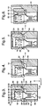
- the electrical connector 10 in accordance with the present invention comprises a housing 12 having a first part 14 and a second part 16; and one or more electric contacts 18 (only one is shown in the drawings).
- the first part 14 of the housing has a front face 20 and a rear face 22.
- a channel 24 is formed in the front face 20, and a number of through bores 26 (only one is shown in the drawings) extend between the rear face 22 and the channel 24 in a direction substantially perpendicular to the rear face.
- the channel 24 has an internal wall 28 which is remote from the front face 20 and preferably substantially parallel to the rear face 22.
- One of the side walls 30 defining the channel 24 has a shoulder 32 directed towards the front face 20, and an angled surface 34 extending between the shoulder and the internal wall 28.
- the shoulder 32 is preferably at a small angle compared to the internal wall 28.
- the angled surface 34 is at a greater angle relative to the internal wall 28 than the shoulder 32.
- the second part 16 of the housing 12 has a front face 36 and a rear face 38, and a number of through bores 40 (only one of which is shown in the drawings) which extend between the front and rear faces in a direction substantially perpendicular to the rear face. Adjacent the front face 36, an internal shoulder 42 is formed in each bore 40. A resilient latch tang 44 is also positioned in each bore 40. The latch tang 44 extends towards the front face 36 and has a lip 46 formed adjacent the free end directed towards the front face and the internal shoulder 42.
- the second part 16 of the housing 12 is positioned in the channel 24 in the first part 14 of the housing, with the rear face 38 of the second part resting on the shoulder 32 in the channel, as shown in Figure 1. In this initial position, the bores 26,40 in the first and second parts 14,16, respectively, are substantially aligned.
- Each electric contact 18 has a front face 48 and first and second rearwardly directed shoulders 50,52.
- the contact 18 is connected to an electrical conductor (not shown) in any suitable manner, such as by way of crimping to a crimp portion 54 on the contact.
- the electric contact 18 is inserted in the direction X into the bore 26 of the first part from the rear face 22 and into the bore 40 of the second part, with the front face 48 of the contact directed towards the internal shoulder 42 in the bore of the second part.
- the contact 18 is inserted until the lip 46 on the latch tang 44 makes a snap fit with the first shoulder 50 on the contact to provide a first lock for the contact, as shown in Figure 1.
- the first lock substantially prevents movement of the contact 18 relative to the housing 12 in a direction opposite to direction X.
- the internal shoulder 42 prevents over insertion of the contact 18 into the bores 26,44 and substantially prevents further movement of the contact relative to the housing 12 in the direction X after the first lock has been achieved.
- the second shoulder 52 on the contact is substantially aligned with the rear face 38 of the second part 16 of the housing 12.
- the second part 16 of the housing 12 is pushed towards the first part 14.
- the rear face 38 of the second part 16 slides on the shoulder 32 and the angled surface 34 so that the second part moves in a direction opposite to direction X, and in a direction Y substantially perpendicular to direction X, relative to the first part 14 to move the bores 26,40 out of alignment and to bring the rear face 38 of the second part 16 of the housing 12 into engagement with the internal wall 28 of the channel 24 (as shown in Figure 2).
- This also brings the second shoulder 52 on the contact 18 into engagement with the internal wall 28 of the channel 24 to provide a second lock for the contact.
- the second lock substantially prevents movement of the contact 18 relative to the housing 12 in a direction opposite to direction X.
- the connector 10 With the first and second locks engaged, the connector 10 is fully assembled. Any suitable means (not shown) may be used to lock the first and second parts 14,16 of the housing 12 in the fully assembled position.
- the contact 18 is mateable with a corresponding contact (not shown) which enters the bore 40 of the second part 16 of the housing 12 through the front face 36 of the second part.
- the electrical connector 10 of Figures 3 to 6 is identical to the electrical connector 10 of Figures 1 and 2.
- Figures 3 to 6 illustrate alternative assembly steps before reaching the fully assembled position.
- the electric contact 18 is inserted in the direction X into the bore 26 of the first part from the rear face 22 and into the bore 40 of the second part, with the front face 48 of the contact directed towards the internal shoulder 42 in the bore of the second part as before.
- the first lock for the contact 18 is not engaged, and the second shoulder 52 of the contact is not aligned with the rear face 38 of the second part 16 of the housing 12.
- the second part 16 of the housing 12 is then pushed towards the first part 14.
- the present invention therefore provides an electrical connector in which the or each electric contact has a double lock (first and second locks) in one direction to prevent withdrawal of the electric contact after the electrical connector is fully assembled. No additional parts are required to establish the double lock. Alternative assembly steps still ensure a double lock for the electric contact in the fully assembled position of the electrical connector.
- the present invention provides an electrical connector which is easier and cheaper to assemble, and lends itself to automated assembly.
Landscapes
- Connector Housings Or Holding Contact Members (AREA)
- Details Of Connecting Devices For Male And Female Coupling (AREA)
Claims (7)
- Connecteur électrique (10) comprenant un logement (12) ayant une première partie (14) et une seconde partie (16) ; et un contact électrique (18), dans lequel la première partie du logement a une face avant (20) et une face arrière (22), un canal (24) formé dans la face avant (20) et ayant une paroi interne (28) distante de la face avant (20), et un alésage traversant (26) s'étendant entre la face arrière (22) et le canal (24) ; dans lequel la seconde partie (16) du logement a une face avant (36), une face arrière (38) ; dans lequel la seconde partie (16) est positionnée dans le canal (24) dans la première partie (14) et est mobile ; et dans lequel le contact électrique (18) a un premier épaulement orienté vers l'arrière (50) et un second épaulement orienté vers l'arrière (52) ; caractérisé en ce que le canal (24) a une paroi latérale (30) avec un épaulement (32) orienté vers la face avant (20) de la première partie (14) et une surface angulaire (34) entre l'épaulement (32) et la paroi interne (28) ; en ce que la seconde partie (16) du logement (12) a un orifice traversant (40) s'étendant entre les faces avant et arrière (36, 38) de la seconde partie, et une languette de verrouillage élastique (44) à l'intérieur de l'alésage (40) orientée vers la face avant (36) avec une lèvre (46) orientée vers la face avant ; en ce que la seconde partie (16) est mobile entre une position d'assemblage initiale dans laquelle la face arrière (38) de la seconde partie (16) est en prise avec l'épaulement (32) dans le canal (24) et les alésages (26, 40) sont sensiblement alignés, et une position d'assemblage complet dans laquelle la face arrière (38) de la seconde partie (16) est en prise avec la paroi interne (28) du canal (24) et les alésages (26, 40) ne sont pas alignés, la face arrière (38) de la seconde partie (16) étant en prise avec la surface angulaire (34) pendant le mouvement de la position d'assemblage initiale à la position d'assemblage complet ; et en ce que le contact électrique (18) est positionné dans les alésages (26, 40), le premier épaulement (50) étant en prise avec la lèvre (46) sur la languette de verrouillage (44) et le second épaulement (52) se mettant en prise avec la paroi interne (28) du canal (24) lorsque la seconde partie (16) du logement est dans la position d'assemblage complet.
- Connecteur électrique selon la revendication 1, dans lequel l'épaulement (32) dans le canal (24) est à un petit angle par rapport à la paroi interne (28) du canal, et la surface angulaire (34) est à un angle plus grand par rapport à la paroi interne.
- Connecteur électrique selon la revendication 1 ou la revendication 2, dans lequel l'alésage (40) dans la seconde partie (16) du logement (12) a un épaulement interne (42) adjacent à la face avant (36) de la seconde partie qui agit comme une butée pour le contact électrique (18).
- Connecteur électrique selon l'une quelconque des revendications 1 à 3, dans lequel la paroi interne (28) du canal (24) est sensiblement parallèle à la face arrière (22) de la première partie (14) du logement (12).
- Connecteur électrique selon l'une quelconque des revendications 1 à 4, dans lequel l'alésage (26) dans la première partie (14) du logement (12) est sensiblement perpendiculaire à la paroi interne (28) du canal (24) ; et dans lequel l'alésage (40) dans la seconde partie (16) du logement est sensiblement perpendiculaire à la face arrière (38) de la seconde partie.
- Connecteur électrique selon l'une quelconque des revendications 1 à 5, dans lequel le premier épaulement (50) du contact électrique (18) est en prise avec la lèvre (46) sur la languette de verrouillage (44) lorsque la seconde partie (16) du logement (12) est dans la position d'assemblage initiale.
- Connecteur électrique selon l'une quelconque des revendications 1 à 5, dans lequel le second épaulement (52) du contact électrique (18) est en prise avec la paroi interne (28) du canal (24) avant que la seconde partie (16) du logement (12) ne soit dans la position d'assemblage complet.
Applications Claiming Priority (2)
| Application Number | Priority Date | Filing Date | Title |
|---|---|---|---|
| DE19847369 | 1998-10-14 | ||
| DE19847369A DE19847369A1 (de) | 1998-10-14 | 1998-10-14 | Elektrischer Verbinder |
Publications (3)
| Publication Number | Publication Date |
|---|---|
| EP0994530A2 EP0994530A2 (fr) | 2000-04-19 |
| EP0994530A3 EP0994530A3 (fr) | 2002-05-29 |
| EP0994530B1 true EP0994530B1 (fr) | 2006-01-11 |
Family
ID=7884451
Family Applications (1)
| Application Number | Title | Priority Date | Filing Date |
|---|---|---|---|
| EP99203031A Expired - Lifetime EP0994530B1 (fr) | 1998-10-14 | 1999-09-17 | Connecteur électrique |
Country Status (3)
| Country | Link |
|---|---|
| EP (1) | EP0994530B1 (fr) |
| BR (1) | BR9904953B1 (fr) |
| DE (2) | DE19847369A1 (fr) |
Families Citing this family (1)
| Publication number | Priority date | Publication date | Assignee | Title |
|---|---|---|---|---|
| DE102005050778B4 (de) | 2005-10-24 | 2020-10-08 | Robert Bosch Gmbh | Kontaktgehäuse sowie elektrische Kontaktvorrichtung |
Family Cites Families (5)
| Publication number | Priority date | Publication date | Assignee | Title |
|---|---|---|---|---|
| JPH01197979A (ja) * | 1988-01-31 | 1989-08-09 | Amp Inc | タブルロックを有するコネクター |
| US5181862A (en) * | 1991-07-29 | 1993-01-26 | Amp Incorporated | Diagnostic header assembly |
| JP2604378Y2 (ja) * | 1993-12-06 | 2000-05-08 | 矢崎総業株式会社 | フロントホルダ付き二重係止コネクタ |
| DE19535979B4 (de) * | 1995-09-27 | 2006-03-23 | The Whitaker Corp., Wilmington | Steckergehäuse mit einem Grundteil und einem Verriegelungsteil sowie Verwendung des Steckergehäuses |
| DE29517133U1 (de) * | 1995-10-28 | 1997-02-27 | Robert Bosch Gmbh, 70469 Stuttgart | Vierpoliger elektrischer Steckverbinder |
-
1998
- 1998-10-14 DE DE19847369A patent/DE19847369A1/de not_active Withdrawn
-
1999
- 1999-09-17 EP EP99203031A patent/EP0994530B1/fr not_active Expired - Lifetime
- 1999-09-17 DE DE69929393T patent/DE69929393T2/de not_active Expired - Lifetime
- 1999-10-11 BR BRPI9904953-8A patent/BR9904953B1/pt not_active IP Right Cessation
Also Published As
| Publication number | Publication date |
|---|---|
| DE69929393T2 (de) | 2006-07-27 |
| BR9904953B1 (pt) | 2014-04-15 |
| DE19847369A1 (de) | 2000-04-20 |
| EP0994530A2 (fr) | 2000-04-19 |
| DE69929393D1 (de) | 2006-04-06 |
| BR9904953A (pt) | 2000-08-29 |
| EP0994530A3 (fr) | 2002-05-29 |
Similar Documents
| Publication | Publication Date | Title |
|---|---|---|
| US6638109B2 (en) | Connector with a side retainer | |
| EP0726617B1 (fr) | Connecteur avec verrouillage secondaire et mécanisme d'accouplement | |
| US6244880B1 (en) | Low-insertion force connector | |
| US4797116A (en) | Electrical connector having a movable contact guide and lance-maintaining member | |
| EP0971442B1 (fr) | Connecteur électrique avec verrouillage latéral | |
| US7204725B2 (en) | Connector and method of assembling it | |
| US4479691A (en) | Connector assembly | |
| US20050106951A1 (en) | Terminal locking mechanism for hybrid electrical connector | |
| WO1996032760A1 (fr) | Prise electrique a cran de blocage secondaire | |
| EP1271705A1 (fr) | Connecteur ayant un limiteur d' ouvrage pour un dispositif de retenue | |
| EP0905819B1 (fr) | Connecteur avec verrouillage | |
| US5755600A (en) | Connector with terminal locking member | |
| US6685506B1 (en) | Connector and a method for connecting such connector with a mating connector | |
| US5647772A (en) | Terminal position assurance system for an electrical connector | |
| EP0660451A2 (fr) | Connecteur | |
| US6435921B2 (en) | Connector and a set of terminal fittings | |
| EP1094559B1 (fr) | Connecteur électrique ayant un dispositif de retenue des contacts | |
| KR100446796B1 (ko) | 커넥터 | |
| EP1006380B1 (fr) | Connecteur électrique et/ou optique | |
| US20090042434A1 (en) | Electrical Connector | |
| US6551146B2 (en) | Connector and a method for assembling a connector | |
| EP0994530B1 (fr) | Connecteur électrique | |
| US5971815A (en) | Electrical connector with terminal locking member | |
| US6669508B2 (en) | Connector | |
| US6488547B2 (en) | Connector with longitudinally spaced locks for retaining terminal fittings |
Legal Events
| Date | Code | Title | Description |
|---|---|---|---|
| PUAI | Public reference made under article 153(3) epc to a published international application that has entered the european phase |
Free format text: ORIGINAL CODE: 0009012 |
|
| AK | Designated contracting states |
Kind code of ref document: A2 Designated state(s): AT BE CH CY DE DK ES FI FR GB GR IE IT LI LU MC NL PT SE |
|
| AX | Request for extension of the european patent |
Free format text: AL;LT;LV;MK;RO;SI |
|
| PUAL | Search report despatched |
Free format text: ORIGINAL CODE: 0009013 |
|
| AK | Designated contracting states |
Kind code of ref document: A3 Designated state(s): AT BE CH CY DE DK ES FI FR GB GR IE IT LI LU MC NL PT SE |
|
| AX | Request for extension of the european patent |
Free format text: AL;LT;LV;MK;RO;SI |
|
| 17P | Request for examination filed |
Effective date: 20021129 |
|
| AKX | Designation fees paid |
Designated state(s): DE ES FR GB IT |
|
| 17Q | First examination report despatched |
Effective date: 20040924 |
|
| GRAP | Despatch of communication of intention to grant a patent |
Free format text: ORIGINAL CODE: EPIDOSNIGR1 |
|
| GRAS | Grant fee paid |
Free format text: ORIGINAL CODE: EPIDOSNIGR3 |
|
| GRAA | (expected) grant |
Free format text: ORIGINAL CODE: 0009210 |
|
| AK | Designated contracting states |
Kind code of ref document: B1 Designated state(s): DE ES FR GB IT |
|
| REF | Corresponds to: |
Ref document number: 69929393 Country of ref document: DE Date of ref document: 20060406 Kind code of ref document: P |
|
| PG25 | Lapsed in a contracting state [announced via postgrant information from national office to epo] |
Ref country code: ES Free format text: LAPSE BECAUSE OF FAILURE TO SUBMIT A TRANSLATION OF THE DESCRIPTION OR TO PAY THE FEE WITHIN THE PRESCRIBED TIME-LIMIT Effective date: 20060422 |
|
| ET | Fr: translation filed | ||
| PLBE | No opposition filed within time limit |
Free format text: ORIGINAL CODE: 0009261 |
|
| STAA | Information on the status of an ep patent application or granted ep patent |
Free format text: STATUS: NO OPPOSITION FILED WITHIN TIME LIMIT |
|
| 26N | No opposition filed |
Effective date: 20061012 |
|
| GBPC | Gb: european patent ceased through non-payment of renewal fee |
Effective date: 20060917 |
|
| PG25 | Lapsed in a contracting state [announced via postgrant information from national office to epo] |
Ref country code: GB Free format text: LAPSE BECAUSE OF NON-PAYMENT OF DUE FEES Effective date: 20060917 |
|
| REG | Reference to a national code |
Ref country code: FR Ref legal event code: PLFP Year of fee payment: 18 |
|
| REG | Reference to a national code |
Ref country code: FR Ref legal event code: PLFP Year of fee payment: 19 |
|
| REG | Reference to a national code |
Ref country code: FR Ref legal event code: PLFP Year of fee payment: 20 |
|
| PGFP | Annual fee paid to national office [announced via postgrant information from national office to epo] |
Ref country code: DE Payment date: 20180927 Year of fee payment: 20 Ref country code: IT Payment date: 20180920 Year of fee payment: 20 Ref country code: FR Payment date: 20180925 Year of fee payment: 20 |
|
| REG | Reference to a national code |
Ref country code: DE Ref legal event code: R082 Ref document number: 69929393 Country of ref document: DE Representative=s name: MANITZ FINSTERWALD PATENT- UND RECHTSANWALTSPA, DE Ref country code: DE Ref legal event code: R082 Ref document number: 69929393 Country of ref document: DE Representative=s name: MANITZ FINSTERWALD PATENTANWAELTE PARTMBB, DE Ref country code: DE Ref legal event code: R081 Ref document number: 69929393 Country of ref document: DE Owner name: APTIV TECHNOLOGIES LIMITED, BB Free format text: FORMER OWNER: DELPHI TECHNOLOGIES, INC., TROY, MICH., US |
|
| REG | Reference to a national code |
Ref country code: DE Ref legal event code: R071 Ref document number: 69929393 Country of ref document: DE |