EP0994367B1 - Neutronendetektor mit Doppelbereich und gammastrahlenbeständiger Schicht - Google Patents
Neutronendetektor mit Doppelbereich und gammastrahlenbeständiger Schicht Download PDFInfo
- Publication number
- EP0994367B1 EP0994367B1 EP99308107A EP99308107A EP0994367B1 EP 0994367 B1 EP0994367 B1 EP 0994367B1 EP 99308107 A EP99308107 A EP 99308107A EP 99308107 A EP99308107 A EP 99308107A EP 0994367 B1 EP0994367 B1 EP 0994367B1
- Authority
- EP
- European Patent Office
- Prior art keywords
- detector
- chamber
- neutron
- gamma
- coating
- Prior art date
- Legal status (The legal status is an assumption and is not a legal conclusion. Google has not performed a legal analysis and makes no representation as to the accuracy of the status listed.)
- Expired - Lifetime
Links
Images


Classifications
-
- G—PHYSICS
- G01—MEASURING; TESTING
- G01T—MEASUREMENT OF NUCLEAR OR X-RADIATION
- G01T1/00—Measuring X-radiation, gamma radiation, corpuscular radiation, or cosmic radiation
- G01T1/16—Measuring radiation intensity
- G01T1/185—Measuring radiation intensity with ionisation chamber arrangements
-
- G—PHYSICS
- G01—MEASURING; TESTING
- G01T—MEASUREMENT OF NUCLEAR OR X-RADIATION
- G01T3/00—Measuring neutron radiation
Definitions
- This invention relates generally to radiation detectors. More particularly, the application relates to a dual range neutron detection device.
- assay of nuclear materials requires measurements of low levels of neutrons in a high gamma environment.
- the 3 He neutron proportional counter is a high sensitivity detector which may be used for low level neutron measurements.
- this detector has a high enough sensitivity to gamma radiation in these applications to make it virtually unusable.
- the primary cause of gamma response in detectors is the interaction of gamma rays with the construction materials of the detectors. The unique construction of this detector reduces the response to gamma radiation, allowing it to be used in high gamma environments.
- a single detector would be advantageous where space limitations prevent the use of two detectors or changing detectors is difficult and/or impractical. The present invention seeks to satisfy that need.
- a dual range neutron detector comprising a chamber which serves as a cathode, an insulator at either end of the chamber, an anode located within the chamber and supported by the insulators, and an electrical connector mounted on one of the insulators for transmission of a signal collected by the anode.
- the chamber is filled with 3 He and an inner wall of the chamber is provided with a boron coating.
- a method of measuring neutron levels in nuclear fuel which includes providing a dual range neutron detector as defined above proximate the nuclear fuel to be measured, and detecting the neutron level in the fuel.
- fuel is spent nuclear fuel.
- a dual range neutron detector of the invention comprising a hermetically sealed chamber 4 which acts as the cathode with a seal 6 and at least one insulator 8 at one end of the chamber 4.
- An anode 10 in the form of a wire is suspended within the chamber along the central longitudinal axis A of the chamber between the seal 6 and the insulator 8.
- An external electrical connector 12 is provided at one end of the chamber for transmission of a signal collected by the anode 10.
- the chamber contains two sensitive materials, namely 3 He gas 14 and a thin coating 16 of boron containing 10 B on the wall 18 of the chamber.
- the 3 He is normally present in the chamber at a pressure ranging from 10.1 kPa (0.1 atmosphere) up to 2030 kPa (20 atmospheres). In some instances pressures greater than 2030 KPa (20 atmospheres) may be employed.
- the boron coating is typically measured by mass of boron per surface area (density). Typical coating densities can range from 0.01 mg/cm 2 to 1.0 mg/cm 2 .
- the boron coating is applied by painting onto the cathode surface, or by flame spraying the material onto the surface. To paint the boron onto the surface, a binder is first applied to the boron which is then suspended in a liquid carrier.
- a typical binder is that supplied by Accheson Colloids. The painting and flame spraying techniques are known to persons of ordinary skill in the art.
- the chamber is typically fabricated from aluminum or stainless steel. Examples of other materials which may be used are metals such as nickel, copper, brass and titanium.
- the chamber may be of any suitable cross-section, but is typically cylindrical, with the cathode as the outer shell and the signal collecting anode suspended in the center with insulators.
- the dimensions of the cylinder typically range from 6,35 mm (0.25 inches) in diameter to 15,2 mm (6 inches) in diameter, or larger.
- the length of the detector may range from about 63,5 mm (2.5 inches) up to 2,03 m (80 inches) or more.
- the boron coating is typically enriched to greater than about 90% of the 10 B isotope, more usually greater than about 92% 10 B.
- the naturally occurring isotopic concentration of boron may be used.
- Naturally occurring boron consists of about 80% 11 B and 20% 10 B.
- the coating may also consist entirely of boron enriched in the "B isotope.
- the boron coating reduces the number of electrons produced in the cathode from entering the active volume of the detector.
- the active volume of the detector is the volume between the anode and the cathode. The volume primarily starts and ends where the anode is exposed within the detector. Boron is employed for this purpose because of its low atomic number, which lowers the gamma production of electrons in the boron itself.
- the total sensitivity of the detector may be varied by adjusting the 3 He gas pressure and the 10 B coating thickness. Sensitivity adjustments may be accomplished by two methods. The first is achieved by adjusting the amount of 3 He within the detector volume which is measured by the filling pressure. An increase in pressure, or amount of 3 He, increases sensitivity, and conversely a reduction in pressure reduces sensitivity. According to the second method, the 10 B coating thickness is varied. Increasing the coating thickness increases detector sensitivity until the coating begins to shield the detector volume by excessive adsorption of neutrons. Excessive coating thicknesses prevent the reaction products from entering the gas volume and thus prevent the signal from being collected on the anode.
- the insulators are typically fabricated from high purity alumina ceramics.
- the ceramics which are used for the seal assembly, item 6 in Figure 1 have metal flanges brazed to them which are then brazed into one end of the detector. The electrical feed through in the center of the insulator is also brazed into place.
- the internal insulator, item 8 in Figure 1 is held in place by mechanically capturing it on the end plate of the detector.
- the seal assembly and internal insulator may also be attached by using epoxy.
- Alternative materials for the insulators are plastics, TEFLON® (polytetrafluoroethylene), glass or other ceramic materials.
- the anode is typically a piece of wire suspended between the insulators, typically tungsten wire.
- Other conductive materials may be used such as stainless steel, nickel or nickel alloys, copper, quartz and various other materials.
- the anode may be welded, crimped, tied or epoxied in place.
- the anode is attached to metal parts mounted on the seal and internal insulator.
- the chamber is hermetically sealed using conventional techniques.
- the hermetic seal is typically accomplished by both welding and brazing the components together. In some instances the components are epoxied, or soldered together.
- the fill gas is introduced into the detector through a hollow metal fill tube which is sealed by cold welding.
- neutrons are neutral particles, in order to be detected, they must be charged by reaction with the materials they encounter in the detector.
- the detection media utilized in the present detector are 3 He gas and the thin boron coating. Both materials have been selected in view of their high capture cross-section for neutrons.
- the 3 He gas and the boron coating are subjected to an electric field within the chamber and the neutrons present react with the materials in a way such that charged particles are produced which ionize the 3 He gas.
- the resulting ions produce an electric signal in the form of output electronic pulses collected at the anode.
- the size of each pulse is proportional to the energy of the reaction of the neutron with the specific material.
- the detector of the invention is a neutron proportional counter.
- the 3 He reaction produces an energy response up to 765 KeV.
- the 10 B reaction produces a response up to 1470 KeV.
- Figure 2 shows an integral bias curve obtained by plotting counts per 10 seconds against discriminator (volts).
- Detectors SK-2015-BN and SK-2016-BC are examples of the invention and incorporate a 10 B coating on the cathode.
- Detector SK-2016-MC is a conventional 3 He filled detector without a 10 B coating.
- This graph shows the counting rate versus the energies from the 3 He and 10 B response from the detectors.
- discriminator levels greater than 4.5 volts (765 KeV) there is still a neutron response for the detectors of the invention, and none for the conventional 3 He detector.
- pulse height discrimination of the detector signal can be used.
- the dual range advantage can also be obtained by changing the tube operating bias.
- the discriminator By electronically measuring the energies from above 150 KeV, the response from both the 3 He gas and the 10 B coating will be measured for maximum sensitivity applications. By electronically discriminating all energies below 765 KeV, the higher 10 B reaction energies will be utilized for reduced sensitivity applications. This is shown in the integral bias curve of Figure 2. For maximum sensitivity use the discriminator would be set at approximately 0.5 to 1.0 volts. For reduced sensitivity use the discriminator would be set at approximately 4.5 volts.
- Table I below displays the total sensitivity and the sensitivity from 10 B reactions greater than 765 KeV of 12 prototype detectors.
- Figure 3 shows detector response in a mixed neutron and gamma field.
- the detector which has only the typical carbon coating on the body shell shows elevated counts due to gamma response at 1500 volts.
- the detector with the boron coating shows no appreciable increase due to gamma response at 1500 volts.
- the reduction in count rate at the 1500 volt point can be seen due to the addition of the boron at the cathode.
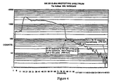
- Figure 4 shows a spectrum of the energy response of the detector. Signals up to energy 765 KeV are due primarily to the 3 He reaction. Signals greater than 765 KeV are due to the 10 B reaction. Channel 85 and lower shows the response from the 3 He and lower energy 10 B reactions, less than 765 KeV. Above channel 85 shows the response from the 10 B reactions up to 1470 KeV.
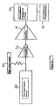
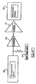
- Figures 5A and 5B show two typical circuit diagrams use in operation of the device.
- Figure 5A depicts the system used to operate the detector with a fixed or variable discriminator and a fixed or variable high voltage supply.
- the detector 22 is connected via a high voltage supply 24 to a preamplifier 26 connected to an amplifier 28.
- the amplifier is connected to a discriminator 30 which may be variable or fixed.
- a counter 32 is connected to the discriminator. When a fixed discriminator is used the gamma discrimination is accomplished by decreasing the high voltage. When a fixed high voltage is used, the discriminator is varied to eliminate the gamma response.
- Figure 5B shows the circuit employing a multi-channel analyzer. This circuit is similar to that depicted in Figure 5A except that the amplifier is connected a multi-channel analyzer 34 which looks at all pulses and generates a graph based on pulse heights. When this system is used, the gamma response is eliminated by only integrating the neutron signal which appears above the gamma signal.
- FIG 6 shows an actual application of the invention for the Plutonium Canister Counter (PCC) used to measure spent nuclear fuel. This application is described in more detail in the Example below.
- PCC Plutonium Canister Counter
- the device is used as follows.
- the detector measures thermal neutrons. If the neutrons emitted from the sample are not in the thermal energy range, the detector must be placed in a moderator, which is typically high density polyethylene. In the event the gamma field is excessive, additional shielding may be added between the detector and the sample.
- a single detector may be used or multiple detectors based upon the measurement efficiency required and the expected neutron activity of the sample. The higher the efficiency required, the more detectors are needed.
- the sample to be measured is placed external to the detector or detector moderator assembly.
- the neutrons emitted from the sample are measured by the detector for a fixed period of time.
- the reactivity of the source can be established by the number of events (counts) measured by the detector for a fixed period of time.
- a discriminator is an electronic cutoff point which allows pulses collected from the detector below a certain size to be eliminated from the measured signal. Pulses from the 3 He reaction have a smaller height, or size, than the higher energy pulses from the 10 B reaction products.
- the discriminator level can be left at a fixed level and the detector high voltage can be reduced which runs the detector signal at a reduced pulse height. This will reduce the gamma induced, or 3 He reaction pulses to a height smaller than the preset discriminator, thus eliminating them from the collected signal.
- the voltage can be left at a fixed value and the discriminator can be adjusted, raised, to eliminate the smaller gamma induced or 3 He reaction pulses, eliminating them from the collected signal.
- the amplification from the amplifier can be reduced to reduce the pulse size. This will reduce the gamma induced or 3 He reaction pulses to levels below the discriminator, eliminating them from the collected signal.
- the unwanted gamma induced or 3 He reaction pulses can be eliminated from the measured signal by simply using the pulse height spectrum accumulated on the pulses height analyzer (multi-channel analyzer, MCA).
- MCA acquires data by providing an energy spectrum which is generated through the pulse height of the reaction products.
- An example of a spectrum is seen in Figure 4.
- the count rate can be determined.
- the summing of the counts for specific areas of the spectrum can be accomplished which allows elimination from the total, which permits discrimination between gamma induced or 3 He reaction pulses.
- a device which utilizes a combination of neutron sensitive materials having difference levels of efficiency and energy responses to produce a dual range neutron detector.
- the use of the 3 He reaction provides high sensitivity for low neutron fluxes and the use of the 10 B reaction provides a low sensitivity for high neutron fluxes.
- the combined use of the two sensitive materials, namely a boron coating enriched in 10 B in conjunction with the 3 He gas, increases the detector efficiency and maintains neutron sensitivity in high level gamma fluxes.
- the device possesses a dual range capability by using the higher energy 10 B pulses to operate at a reduced efficiency in a higher gamma flux or when a lower sensitivity is desired in a high neutron flux
- the presence of the boron coating at the cathode reduces the number of gamma induced electrons generated from the cathode wall.
- the device of the invention may be used for high level radiation waste monitoring, particularly where high levels of gamma radiation are present. Application to fuel storage pools where low to high level neutron fluxes are present is also possible.
- the device may be employed as a reactor start-up monitor, and may be utilized to allow extended neutron flux monitoring with a single detector.
- the detector is particularly useful in any application where vastly different levels of neutron and gamma radiation are present. Such instances occur in reactor research work, spent fuel monitoring, nuclear waste assay, and other nuclear safeguards applications.
- the detector of the invention has immediate applications for nuclear waste measurements in high gamma field applications.
- FIG. 6 depicts the use dual range 3 He plus 10 B tube devices for a detector known as a Plutonium Canister Counter (PCC), generally referenced 36.
- PCC 36 utilizes three dual range tubes 38 of the invention to surround a spent fuel canister 40 with a handle 41 containing 22 spent fuel rods 42. Each dual range tube is placed proximate to the spent fuel to facilitate measurement thereof.
- proximate as used in the context of the present invention means that the detector is located in relation to the sample as determined by overall system requirements to enable measurements to be taken. The system requirements will vary based upon the sample activity, and size. Standard practice would place the detector such that a minimum count rate of 0.005 counts per second per active inch of the detector is achieved and a maximum total count rate of less than 10 6 counts per second is not exceeded.
- the canister 40 is disposed in a well 44 and surrounded by water 46 to moderate or slow down neutrons emitted from the spent fuel rods 42.
- Each dual range detector 38 is mounted in a lead sheath 46 which is thicker in the direction of the spent fuel rods.
- Figure 7 shows a side cut-away view of a detector of the invention 38 within a lead sheath 46.
- the detector is connected to a PDT 150W preamplifier 48, as shown in the Figures 5A and 5B.
- the gamma-ray dose at the detector tube position is high and in the range of 20 to 1000 R/h from the fission products in the spent fuel.
- the dual range capability using the 10 B feature permits measurement of neutrons in the high gamma dose.
Claims (8)
- Zweibereichs-Neutronendetektor, aufweisend:eine Kammer (2) mit zwei Enden und einer Innenwand (4), wobei die Kammer zwei Enden und eine Innenwand besitzt, die als eine Kathode dient, und mit 3He Gas (14) gefüllt ist;einen Isolator (8) an jedem Ende der Kammer;eine Anode (10), die innerhalb der Kammer angeordnet ist und von jedem Isolator unterstützt wird;eine Bor-Beschichtung (16) auf der Innenwand der Kammer;einen elektrischen Verbinder (12), der auf einem der Isolatoren zum Übertragen eines durch die Anode gesammelten Signals montiert ist.
- Vorrichtung nach Anspruch 1, wobei das 3He bei einem Druck in dem Bereich von 10,1 kPa (0,1 Atmosphäre) ist 2030 kPa (20 Atmosphären) vorliegt.
- Vorrichtung nach Anspruch 1, wobei die Bor-Beschichtung eine Beschichtungsdichte in dem Bereich von 0,01 mg/cm2 bis 1,0 mg/cm2 aufweist.
- Vorrichtung nach Anspruch 1, wobei die Bor-Beschichtung die natürlich auftretende Isotopenkonzentration von 10B enthält.
- Vorrichtung nach Anspruch 1, wobei die Bor-Beschichtung auf etwa 92 % des 10B Isotops angereichert ist.
- Vorrichtung nach Anspruch 4, wobei die Bor-Beschichtung auf etwa 20 % des 10B Isotops angereichert ist.
- Verfahren zum Messen von Neutronenpegeln in Kernbrennstoff, mit den Schritten(a) Aufstellen eines Zweibereichs-Neutronendetektors in der Nähe des zu messenden Kernbrennstoffs, wobei der Detektor aufweist: eine Kammer mit zwei Enden und einer Innenwand, die als eine Kathode dient, wobei die Kammer zwei Enden und eine Innenwand besitzt und mit 3He Gas gefüllt ist; einen Isolator an jedem Ende der Kammer; eine Anode, die innerhalb der Kammer angeordnet ist und von jedem Isolator unterstützt wird; eine Bor-Beschichtung auf der Innenwand der Kammer; und einen elektrischen Verbinder, der auf einem der Isolatoren zum Übertragen eines durch die Anode gesammelten Signals montiert ist;(b) Detektieren des Neutronenpegels in dem Brennstoff.
- Verfahren nach Anspruch 7, wobei der Brennstoff verbrauchter Kernbrennstoff ist.
Applications Claiming Priority (2)
| Application Number | Priority Date | Filing Date | Title |
|---|---|---|---|
| US10423198P | 1998-10-14 | 1998-10-14 | |
| US104231P | 1998-10-14 |
Publications (2)
| Publication Number | Publication Date |
|---|---|
| EP0994367A1 EP0994367A1 (de) | 2000-04-19 |
| EP0994367B1 true EP0994367B1 (de) | 2005-08-17 |
Family
ID=22299345
Family Applications (1)
| Application Number | Title | Priority Date | Filing Date |
|---|---|---|---|
| EP99308107A Expired - Lifetime EP0994367B1 (de) | 1998-10-14 | 1999-10-14 | Neutronendetektor mit Doppelbereich und gammastrahlenbeständiger Schicht |
Country Status (2)
| Country | Link |
|---|---|
| US (1) | US6426504B1 (de) |
| EP (1) | EP0994367B1 (de) |
Families Citing this family (26)
| Publication number | Priority date | Publication date | Assignee | Title |
|---|---|---|---|---|
| US6678343B1 (en) * | 2000-02-14 | 2004-01-13 | The United States Of America As Represented By The Secretary Of The Army | Neutron spectrometer with titanium proton absorber |
| US6349124B1 (en) * | 2000-02-14 | 2002-02-19 | The United States Of America As Represented By The Secretary Of The Army | Dodecahedron neutron spectrometer |
| US20030213917A1 (en) * | 2002-05-20 | 2003-11-20 | General Electric Company | Gamma resistant dual range neutron detector |
| US7078705B1 (en) * | 2003-09-30 | 2006-07-18 | The Regents Of The University Of California | Neutron and gamma detector using an ionization chamber with an integrated body and moderator |
| CA3090413C (en) | 2004-06-04 | 2023-10-10 | Abbott Diabetes Care Inc. | Glucose monitoring and graphical representations in a data management system |
| US8330116B2 (en) * | 2008-06-16 | 2012-12-11 | Proportional Technologies, Inc. | Long range neutron-gamma point source detection and imaging using rotating detector |
| US9606248B2 (en) * | 2009-04-13 | 2017-03-28 | General Electric Company | Neutron sensitivity using detector arrays |
| US8084747B2 (en) * | 2009-04-13 | 2011-12-27 | General Electric | Composite dielectric fins in enhanced area boron coated neutron detectors |
| US8129690B2 (en) * | 2009-04-13 | 2012-03-06 | General Electric Company | High sensitivity B-10 neutron detectors using high surface area inserts |
| US7952078B2 (en) | 2009-04-13 | 2011-05-31 | General Electric Company | Neutron sensitivity by increasing boron surface area |
| US7910893B2 (en) * | 2009-04-13 | 2011-03-22 | General Electric Company | B10 neutron detector in pie shaped sectors |
| US8569710B2 (en) * | 2009-06-02 | 2013-10-29 | Proportional Technologies, Inc. | Optimized detection of fission neutrons using boron coated straw detectors distributed in moderator material |
| US9817138B2 (en) | 2009-08-27 | 2017-11-14 | Douglas S. McGregor | Gas-filled neutron detectors and imaging system and array of such detectors |
| WO2011025853A1 (en) * | 2009-08-27 | 2011-03-03 | Mcgregor Douglas S | Gas-filled neutron detectors having improved detection efficiency |
| US7964852B2 (en) | 2009-09-18 | 2011-06-21 | General Electric Company | Neutron sensitivity using detector arrays |
| US8080807B2 (en) * | 2009-09-22 | 2011-12-20 | General Electric Company | Using UV light source for self testing gas filled gamma and neutron detectors |
| US8565364B2 (en) * | 2009-11-16 | 2013-10-22 | General Electric Company | Water based dispersions of boron or boron compounds for use in coating boron lined neutron detectors |
| WO2011143512A1 (en) * | 2010-05-12 | 2011-11-17 | Lacy Jeffrey L | Neutron detectors for active interrogation |
| EP2569799A4 (de) * | 2010-05-13 | 2015-01-21 | Proportional Technologies Inc | Abgedichtete borbeschichtete strohdetektoren |
| US10136845B2 (en) | 2011-02-28 | 2018-11-27 | Abbott Diabetes Care Inc. | Devices, systems, and methods associated with analyte monitoring devices and devices incorporating the same |
| FR2975108A1 (fr) * | 2011-05-12 | 2012-11-16 | Onectra | Procede de depot de bore sur une tole metallique pour appareil de detection de neutrons ou chambre d'ionisation |
| US8502157B2 (en) * | 2011-09-09 | 2013-08-06 | General Electric Company | Boron containing coating for neutron detection |
| US20130119261A1 (en) * | 2011-11-10 | 2013-05-16 | General Electric Company | Neutron detector and method for detecting neutrons |
| DE102012108766A1 (de) * | 2012-09-18 | 2014-03-20 | CDT Cascade Detector Technologies GmbH | Neutronendetektoreinheit sowie Neutronendetektoranordnung |
| US9217793B2 (en) * | 2012-10-25 | 2015-12-22 | Schlumberger Technology Corporation | Apparatus and method for detecting radiation |
| JP6214095B2 (ja) | 2014-06-13 | 2017-10-18 | 三菱重工メカトロシステムズ株式会社 | 中性子モニター装置及び中性子測定方法 |
Family Cites Families (13)
| Publication number | Priority date | Publication date | Assignee | Title |
|---|---|---|---|---|
| GB1133789A (en) * | 1966-07-22 | 1968-11-20 | Atomic Energy Authority Uk | Improvements in or relating to neutron flux detectors |
| US3956654A (en) * | 1975-02-03 | 1976-05-11 | Westinghouse Electric Corporation | Long lived proportional counter neutron detector |
| US4086490A (en) * | 1976-07-07 | 1978-04-25 | Westinghouse Electric Corporation | Wide range neutron detection system |
| US4121106A (en) * | 1977-02-08 | 1978-10-17 | General Electric Company | Shielded regenerative neutron detector |
| JPS5927873B2 (ja) * | 1979-11-15 | 1984-07-09 | 株式会社東芝 | 中性子検出器 |
| US4476391A (en) * | 1982-03-08 | 1984-10-09 | Mobil Oil Corporation | Method for improving accuracy in a neutron detector |
| US4634568A (en) * | 1983-10-19 | 1987-01-06 | General Electric Company | Fixed incore wide range neutron sensor |
| US5002720A (en) * | 1989-06-30 | 1991-03-26 | The United States Of America As Represented By The Secretary Of The Air Force | Electret enabled thermal neutron flux detection and measurement |
| FR2670301B1 (fr) * | 1990-12-07 | 1993-02-12 | Merlin Gerin | Dispositif de detection neutronique a dynamique etendue pour le controle et la commande des reacteurs nucleaires. |
| US5180917A (en) * | 1991-08-08 | 1993-01-19 | Schlumberger Technology Corporation | Self-calibrating proportional counter |
| US5399863A (en) * | 1993-10-19 | 1995-03-21 | Mission Research Corporation | Detector for thermal neutrons utilizing alternating boron slabs and CCD arrays |
| US5726453A (en) * | 1996-09-30 | 1998-03-10 | Westinghouse Electric Corporation | Radiation resistant solid state neutron detector |
| US5973328A (en) * | 1997-10-29 | 1999-10-26 | Lockheed Martin Energy Research Corporation | Neutron detector using sol-gel absorber |
-
1999
- 1999-10-14 US US09/418,997 patent/US6426504B1/en not_active Expired - Lifetime
- 1999-10-14 EP EP99308107A patent/EP0994367B1/de not_active Expired - Lifetime
Also Published As
| Publication number | Publication date |
|---|---|
| EP0994367A1 (de) | 2000-04-19 |
| US6426504B1 (en) | 2002-07-30 |
Similar Documents
| Publication | Publication Date | Title |
|---|---|---|
| EP0994367B1 (de) | Neutronendetektor mit Doppelbereich und gammastrahlenbeständiger Schicht | |
| US20030213917A1 (en) | Gamma resistant dual range neutron detector | |
| EP0732730B1 (de) | Gas-ionisations-netzdetektoren für die radiographie | |
| US4447727A (en) | Large area neutron proportional counter and portal monitor detector | |
| Ruddy et al. | Nuclear reactor power monitoring using silicon carbide semiconductor radiation detectors | |
| US4086490A (en) | Wide range neutron detection system | |
| US4481421A (en) | Lithium-6 coated wire mesh neutron detector | |
| US4071764A (en) | Gamma and alpha compensated fission chamber | |
| Landsberger et al. | Compton suppression neutron activation analysis: past, present and future | |
| CA1084176A (en) | Self-powered neutron flux detector assembly | |
| US4501988A (en) | Ethylene quenched multi-cathode Geiger-Mueller tube with sleeve-and-screen cathode | |
| CN1053763C (zh) | 测井用伴随α中子管 | |
| Deruytter et al. | The accurate fission cross-section of 235U from 0· 002 to 0· 15 eV and its reference value at 2200 m/s | |
| Anderson et al. | A focusing gas scintillation proportional counter | |
| Wehring et al. | Application of cold-neutron prompt gamma activation analysis at the University of Texas reactor | |
| US4091288A (en) | Threshold self-powered gamma detector for use as a monitor of power in a nuclear reactor | |
| JP4395054B2 (ja) | 放射線測定装置及び放射性廃棄物検査方法 | |
| US4638159A (en) | Graded shaped spatial resolution nuclear detectors | |
| Tomitani et al. | Large area proportional counter for assessment of plutonium lung burden | |
| Gloystein et al. | A two-detector anticoincidence system for reduction of Compton scattered high energy γ-ray background in PIXE analysis | |
| US2683221A (en) | Particle and gamma-ray energy spectrometer | |
| Prasad et al. | Uranium‐233 fission detectors for neutron flux measurement in reactors | |
| Maddox et al. | A one-dimensionally position-sensitive scintillation detector | |
| Xia et al. | Reactor Nuclear Measurements and Radiation Monitoring | |
| Lafont et al. | Multitube monitors: a new-generation of neutron beam monitors |
Legal Events
| Date | Code | Title | Description |
|---|---|---|---|
| PUAI | Public reference made under article 153(3) epc to a published international application that has entered the european phase |
Free format text: ORIGINAL CODE: 0009012 |
|
| AK | Designated contracting states |
Kind code of ref document: A1 Designated state(s): FR GB |
|
| AX | Request for extension of the european patent |
Free format text: AL;LT;LV;MK;RO;SI |
|
| 17P | Request for examination filed |
Effective date: 20001019 |
|
| AKX | Designation fees paid |
Free format text: FR GB |
|
| REG | Reference to a national code |
Ref country code: DE Ref legal event code: 8566 |
|
| GRAP | Despatch of communication of intention to grant a patent |
Free format text: ORIGINAL CODE: EPIDOSNIGR1 |
|
| RIN1 | Information on inventor provided before grant (corrected) |
Inventor name: BEDDINGFIELD, DAVID HARRIS Inventor name: JOHNSON, NATHAN HERBERT Inventor name: MENLOVE, HOWARD OLSON |
|
| GRAS | Grant fee paid |
Free format text: ORIGINAL CODE: EPIDOSNIGR3 |
|
| GRAA | (expected) grant |
Free format text: ORIGINAL CODE: 0009210 |
|
| AK | Designated contracting states |
Kind code of ref document: B1 Designated state(s): FR GB |
|
| REG | Reference to a national code |
Ref country code: GB Ref legal event code: FG4D |
|
| ET | Fr: translation filed | ||
| PLBE | No opposition filed within time limit |
Free format text: ORIGINAL CODE: 0009261 |
|
| STAA | Information on the status of an ep patent application or granted ep patent |
Free format text: STATUS: NO OPPOSITION FILED WITHIN TIME LIMIT |
|
| 26N | No opposition filed |
Effective date: 20060518 |
|
| PGFP | Annual fee paid to national office [announced via postgrant information from national office to epo] |
Ref country code: GB Payment date: 20061025 Year of fee payment: 8 |
|
| GBPC | Gb: european patent ceased through non-payment of renewal fee |
Effective date: 20071014 |
|
| PG25 | Lapsed in a contracting state [announced via postgrant information from national office to epo] |
Ref country code: GB Free format text: LAPSE BECAUSE OF NON-PAYMENT OF DUE FEES Effective date: 20071014 |
|
| REG | Reference to a national code |
Ref country code: FR Ref legal event code: PLFP Year of fee payment: 17 |
|
| PGFP | Annual fee paid to national office [announced via postgrant information from national office to epo] |
Ref country code: FR Payment date: 20151019 Year of fee payment: 17 |
|
| REG | Reference to a national code |
Ref country code: FR Ref legal event code: ST Effective date: 20170630 |
|
| PG25 | Lapsed in a contracting state [announced via postgrant information from national office to epo] |
Ref country code: FR Free format text: LAPSE BECAUSE OF NON-PAYMENT OF DUE FEES Effective date: 20161102 |