EP0994065A1 - Method and device for compensating crane boom deformation in load lifting and placing - Google Patents
Method and device for compensating crane boom deformation in load lifting and placing Download PDFInfo
- Publication number
- EP0994065A1 EP0994065A1 EP99117500A EP99117500A EP0994065A1 EP 0994065 A1 EP0994065 A1 EP 0994065A1 EP 99117500 A EP99117500 A EP 99117500A EP 99117500 A EP99117500 A EP 99117500A EP 0994065 A1 EP0994065 A1 EP 0994065A1
- Authority
- EP
- European Patent Office
- Prior art keywords
- crane boom
- deformation
- boom
- crane
- load
- Prior art date
- Legal status (The legal status is an assumption and is not a legal conclusion. Google has not performed a legal analysis and makes no representation as to the accuracy of the status listed.)
- Withdrawn
Links
Images


Classifications
-
- B—PERFORMING OPERATIONS; TRANSPORTING
- B66—HOISTING; LIFTING; HAULING
- B66C—CRANES; LOAD-ENGAGING ELEMENTS OR DEVICES FOR CRANES, CAPSTANS, WINCHES, OR TACKLES
- B66C13/00—Other constructional features or details
- B66C13/18—Control systems or devices
- B66C13/46—Position indicators for suspended loads or for crane elements
-
- B—PERFORMING OPERATIONS; TRANSPORTING
- B66—HOISTING; LIFTING; HAULING
- B66C—CRANES; LOAD-ENGAGING ELEMENTS OR DEVICES FOR CRANES, CAPSTANS, WINCHES, OR TACKLES
- B66C13/00—Other constructional features or details
- B66C13/18—Control systems or devices
- B66C13/20—Control systems or devices for non-electric drives
-
- B—PERFORMING OPERATIONS; TRANSPORTING
- B66—HOISTING; LIFTING; HAULING
- B66C—CRANES; LOAD-ENGAGING ELEMENTS OR DEVICES FOR CRANES, CAPSTANS, WINCHES, OR TACKLES
- B66C23/00—Cranes comprising essentially a beam, boom, or triangular structure acting as a cantilever and mounted for translatory of swinging movements in vertical or horizontal planes or a combination of such movements, e.g. jib-cranes, derricks, tower cranes
- B66C23/88—Safety gear
- B66C23/90—Devices for indicating or limiting lifting moment
- B66C23/905—Devices for indicating or limiting lifting moment electrical
Definitions
- the invention relates to a method and device for compensating for crane boom deformation during load lifting and placing.
- FIG. 3 depicts a crane boom 1 of a crane in the unloaded condition, a load 2 to be lifted being secured to the crane hook.
- the lifting force F lift which counteracts the force resulting from the weight of the load, F L , is gradually increased. Only when the force F lift exceeds the force F L is the load lifted from the ground.
- the lifting force F lift is still somewhat less than the force F L incurred by the weight of the load, considerable forces act on the crane boom 1 even though the load 2 to be lifted is still fully on the ground.
- the deformation of the crane boom 1 caused by the lifting force results in an increase in the horizontal distance of the boom jib away from the fulcrum point of the upper structure, this distance generally being termed radius or length of jib.
- Fig. 4b depicts vectorially the forces acting on the load 2 when the boom is deformed in such manner.
- the force F lift which acts on the load is composed of a vertical component F lift , for overcoming the weight force F L incurred by the load, and a horizontal component F p .
- the force F P acting in the horizontal direction results in the load swinging upon being lifted. This may result in hazardous situations when e.g. unloading concrete wall elements from a truck since the lifted load has uncontrolled movement and, thus, becomes a hazard to man and equipment in the vicinity.
- the crane operator To compensate for the deformation of the boom during lifting and placing of a load, the crane operator must change the angle of the boom 1 by actuating the elevating mechanism 3 in order to compensate for the increase or decrease in radius resulting from deformation. Thus, the operator would compensate by elevating the boom during lifting and compensate the reduced deformation of the boom when placing the load by lowering the boom. Since operation of the crane boom must always be as near optimum as possible, and the deformation of the crane boom may be considerable as a result of the high forces involved, proper compensation is important for lifting and placing a load.
- the crane operator acts as the controller.
- the flow of information in such a compensating action is illustrated in Fig. 6.
- the crane operator observes the working area and takes note, e.g. when lifting a load, of the momentary radius of the crane boom in the unloaded condition. This serves as the target value for him for the radius of the boom in the complete elevating procedure.
- a device for limiting the loading moment shows him the information obtained via sensors as to the actual condition of the boom, it being particularly the information regarding the radius that is of importance to him, this serving as the actual value for his controlling response.
- other values as regards the actual condition of the crane could also be displayed to be likewise taken into account in compensating the situation.
- the crane operator needs to always keep an eye on the working area, in addition to noting the displayed actual values, to keep a check on the effect of his actions.
- An object of the present invention is to provide a method and device for compensating the deformation of a crane boom upon lifting and placing of a load by which safety in crane operation may be enhanced.
- a controller device which receives data pertaining to the sensed deformation of the crane boom, as well as a target value for the position of the crane boom. From these two input variables, i.e. the target value for the position of the crane boom and the actual value of crane boom deformation as measured or established from measured variables, suitable control signals are established by a controller device which signal or control at least one positioner for the crane boom.
- the crane boom is, thus, maintained in a suitable position during lifting or placement of a load, substantially in its target position.
- the position of the crane boom is modified so that the target position of the crane boom, more particularly of the crane boom jib, remains substantially unchanged.
- the jib of the crane boom is thereby maintained plumb above the load to be lifted without any horizontal displacement, irrespective of the magnitude of the momentary lifting force.
- the angle of elevation of the crane boom may be adjusted by the boom elevating mechanism so that the crane boom jib remains plumb above the load to be lifted even with increasing curvature of the crane boom.
- the controlling action may also be achieved by modifying concurrently several manipulated variables such as, e.g., the length of the crane boom and the angle of elevation, as long as it is achieved during lifting or placement of a load that the jib of the boom always remains substantially directly above the load which is standing on the ground despite changes in boom condition resulting from the lifting forces.
- the measured values of various sensors may be employed.
- a position transducer arranged at the jib of the crane boom for measuring at the lower end the momentary angle of elevation of the crane boom jib; a position transducer disposed on the crane boom jib and measuring the momentary angle of elevation of the crane boom jib; a linear transducer for measuring the overall length of the crane boom; a pressure transducer on the elevating mechanism, especially on the elevating cylinder; a transducer for measuring the load or change in load of a single section (i.e., a telescoping section of the boom), such as one or more strain gauges or a load sensing roller arranged at the upper end of the crane boom and located on the upper end of the elevating jib for measuring the force acting momentarily on the jib of crane boom. It is possible thereby to make use of the data provided by all of the above sensors in
- the deformation of the crane boom may be detected e.g. by making use only of the data of a position transducer on the underside or in the lower region of the boom, a position transducer on the upper side or in the upper region of the crane boom and a linear transducer which senses the overall length of the crane boom.
- the data of other sensors for the controlling action from which the actual deformation of the crane boom may be detected. This may also be done e.g. by means of the data of a pressure transducer on the elevating cylinder or a linear transducer for detecting the length of the crane boom as a whole.
- the deformation of the crane boom may be detected by the actual value of the radius of the crane boom being sensed by one or more suitable sensors. It is also possible as described above, to detect the magnitude of the momentary deformation or radius of the crane boom from individual or several measured variables of the crane, such as the actual boom length or actual boom elevation, in conjunction with the momentary lifting force. In general, each and every individual measured variable or combination of measured values may be used to determine the deformation of the crane boom from which it may be detected how the deformation or radius of the crane boom has changed. This then provides a measure of the horizontal spacing between the standing load and boom jib.
- the controller device may also be furnished advantageously with even further values, such as the desired rate and direction of movement of the hoisting or lifting mechanism.
- This manipulated variable may be entered by the crane operator via a control lever. From the desired rate of the hoisting mechanism the controller is able to detect the deformation time profile that the crane boom will probably have and, thus, suitably control the positioner of the crane boom to maintain the latter in its target position.
- the target value for the position of the crane boom it is preferred to use the radius of the boom immediately prior to placement of a load or immediately prior to lifting a load, the crane boom jib in each case being located plumb above the load without any lateral displacement.
- the controlling action is in accordance with this target value, the conditions of the crane boom in lifting or placing a load as shown in Figs. 4 and 5 may be avoided. It is also possible, however, to take the position of the crane boom on activation of the controller device as the target value. It would then be the task of the crane operator to make sure that the controller device is activated at a suitable moment in time, i.e. when the boom jib is precisely above the load.
- the signals output by the controller device are preferably those with which the positioner of the crane boom, such as the elevating mechanism of the crane may be controlled, so that the rate of change in the angle of elevation of the crane boom, and also the direction of the change in the angle of elevation, may be controlled via the rate and direction of movement of the elevating mechanism.
- the horizontal departure of the crane boom jib from the target position, the position plumb above the load may be controlled. For example, in the operating condition as shown in Fig.
- the elevating mechanism can be controlled so that the angle of elevation of the crane boom is increased, thereby returning the jib of the crane boom to a position which is plumb above the load to be lifted.
- control the hoisting mechanism as the crane boom positioner i.e. by controlling the hoisting mechanism so that the rate and/or direction of movement of the hoisting mechanism is controlled.
- the controlling action may be done, for example, in conjunction with the control of the elevating mechanism, as described above, so that the complete lifting or placement action of a load is controlled so that no jerking movements or undesirable side swinging movements of the load occur.
- controller device needs only to receive suitable input variables from which the deformation or actual departure of the crane boom from a target condition may be sensed in order to determine therefrom suitable control signals which are then output to bring the crane boom, more particularly the crane boom jib, to the desired position.
- a plurality of input variables are applied to the controller device, such as the actual value of the angle of the boom, the actual value of the length of the boom, the measured lifting force and the like, and furthermore, a plurality of output variables need to be output from the controller device, such as the direction and rate of movement of the hoisting mechanism and the direction and rate of change of the actual position of the elevating mechanism, it is of advantage to use a fuzzy controller.
- This kind of control may be appreciated as a kind of fuzzy expert system, the control response of which may be defined in a quasi-natural language on the basis of linguistic expressions, one exemplary definition of the controlling action being e.g.:
- the preceding logical statement relates to a situation wherein a large control deviation, such as a long radius, occurs, and the crane operator further dictates that lifting is to be achieved at a relatively high rate.
- the fuzzy controller device would output control signals which prompt a fast change in the radius to the target position, such as a fast increase in the angle of elevation of the crane boom relative to the horizontal, and at the same time the hoisting mechanism is controlled so that the rate at which the load is to be lifted is made to be relatively slow, i.e. slower than defined by the crane operator.
- a fuzzy control action is composed of a plurality of such linguistic conditions for describing the various possible control actions.
- control actions comprise the control algorithm.
- recourse may be made to the experience of the crane operator who, as already mentioned, needs to implement boom elevating and lowering actions manually in the usual manner.
- An apparatus in accordance with the invention for compensating for the deformation of a crane boom in lifting or placing a load comprises a positioner for positioning the crane boom so that it may be maintained substantially in a target position, i.e., so that the crane boom jib exhibits substantially no horizontal displacement from a target position. Further, a measuring device, or a combination of several measuring devices, is provided in a controller device for detecting the deformation of the crane boom for defining a target value for the crane boom position. The positioner for the crane boom is coupled to the controller device so that the target position of the crane boom may be set by the controller device from the defined target and actual values.
- the device for measuring or detecting the deformation of the crane boom is a sensor, or a combination of several sensors, capable of measuring or detecting the radius and/or curvature of the crane boom, as indicated above.
- Sensors may be provided which measure, e.g., the boom length, the angle of elevation of the boom, or the actual lifting force acting on the crane boom. It is not necessary, of course, as already mentioned above, that all of the aforementioned sensors are used. It is possible that only one or more sensors are used in combination for measuring or detecting the deformation of the crane boom.
- the elevating mechanism of the crane is used as the positioner for controlling the position of the crane boom and maintaining the boom at a target position.
- the rate and/or direction of the change in the angle of elevation of the crane boom may be adjusted in order to maintain the target position.
- the hoisting mechanism of the crane for the controlling action.
- the elevating mechanism and hoisting mechanism in combination for suitably maintaining the target position of the crane boom, such as by adapting the lifting force produced by the hoisting mechanism in lifting a load to the momentary position of the elevating mechanism so that no excessive or jerking deformation of the crane boom may occur.
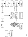
- Fig. 1 there is illustrated an embodiment of a control loop in accordance with the invention whereby the crane operator is able to switch the controller in and out of circuit and to define merely manipulated variables or target variables for the direction and/or rate of movement of the hoisting mechanism for the controller.
- the crane operator is thus able, e.g., via a single control lever for the hoisting mechanism, to affect lifting and placing of a load with the controller device controlling the boom so that the crane boom jib is always maintained above the load (at the target position) and no horizontal shifting of the jib occurs which, as described above, may result in hazardous swinging when lifting a load.
- the controller 10 as shown in Fig. 1 receives input of data representing actual values of variables as measured by sensors 12 which define the actual condition of the boom.
- Useful data may be provided by sensors which measure the curvature or radius of the boom; the angle of elevation of the boom, more particularly the angle of elevation at the upper and lower ends of the boom, respectively; the boom length; the forces acting on the boom; or the pressure existing at the elevating cylinder.
- the actual value of the angle of elevation of the boom and the actual value of the length of the boom are particularly useful values.
- boom monitor 14 which may also handle additional functions, such as load moment limiting (LML). Boom monitor 14 then applies the values as measured by the sensors and, where necessary, further processed, to the controller 10. At this stage certain features may already be extracted from the measured values, for example, in making use of characteristics or suitable computations.
- LML load moment limiting
- the boom monitor 14 may further record the actual values of the boom characteristics measured by the sensors upon activation of the controlling action, such as the sensed radius, as the target values to which the subsequent controlling action is to respond. It is likewise possible, as evident from Fig. 1, to record the target value in a separate memory MEM 16. In this arrangement the target value may be recorded, e.g., upon activating the controller. It is also possible, however, to store the target value automatically upon sensing the load or upon lifting the load. This may be done, e.g., as soon as a freely selectable tensile force (e.g. 50 KG) is exceeded. It is the difference between this stored target value and the measured actual value of the radius - the error - that is applied to the controller.
- a freely selectable tensile force e.g. 50 KG
- Input from the operator is provided manually by levers and switches or the like, identified collectively at 18 in Figure 1. Signals for operator input of movement direction, rate of movement, etc., and activation or de-activation of the controller may be thus input. From the input variables the controller detects, by means of the fuzzy control algorithm specified by linguistic expressions, the output variables for controlling the hoisting mechanism and/or the elevating mechanism and/or the telescoping mechanism. Signals controlling the direction and/or rate of change are output, as shown at 10a and 10b to the hoisting mechanism, and/or at 10c and 10d to the elevating mechanism. Such control may also be applied by the controller to a telescoping mechanism (not shown).
- the hoisting mechanism influences the deformation of the boom via the lifting force applied to the lifting cable supported by the boom.
- the elevating mechanism sets or adjusts the angle of elevation of the boom. In this arrangement the length of the boom or the angle of elevation must always be adjusted or controlled so that the momentary deformation of the crane boom resulting from the changing load is compensated in each case so that the jib of the crane boom has substantially no horizontal departure from its target position.
- Fig. 2 there is illustrated a flow diagram of the information in an operation for compensating for boom deformation in accordance with the invention.
- the working area is firstly observed by the crane operator.
- the crane operator sees that, e.g., a load is to be lifted, he activates the controlling action and defines a manipulated value for the hoisting mechanism via a control lever.
- the controlling action receives as additional input data representing the actual values detected by the sensors for the deformation of the boom, which are transferred from the boom monitor by, for example, a CAN bus, to the controlling action.
- control signals for the movement of the winch of the hoisting mechanism and/or for the elevating mechanism are output, both of which influence the position and shape of the boom. Accordingly, the crane operator simply defines a manipulated value, e.g., rate of lift for desired lifting of a load.
- the controlling action controlling the crane boom such as the elevating mechanism and hoisting mechanism, take into account the defined manipulated value so that substantially no variation of the radius of the crane boom occurs.
- the boom monitor which may also serve to define or limit the loading moment, as described above, indicates the measured actual value of the crane boom to the crane operator.
- the controlling action in accordance with the invention relieves the crane operator from some of the monitoring tasks typically required of him hitherto in lifting and placing a load so that he is now able to more fully concentrate on the working area.
Abstract
The present invention relates to a device and method for controlling,
or compensating for, the deformation of a crane boom (1) in lifting or placing
a load (2). The deformation of a crane boom (1) is detected or measured and the
detected or measured deformation is applied to a controller device (10). A
target value for the position of the crane boom (1) is applied to the controller
device (10) and the controller device (10) outputs signals which control or drive at
least one positioner for the crane boom (1) so that the crane boom (1) is
maintained substantially in its target position.
Description
- The invention relates to a method and device for compensating for crane boom deformation during load lifting and placing.
- It is known that a crane boom deforms relative to its unloaded condition when lifting a load, this deformation being proportional to the load. Optimizing the capacity of a crane boom requires that these deformations be taken into account.
- Problems may result especially in lifting and placing a load. Fig. 3 depicts a
crane boom 1 of a crane in the unloaded condition, aload 2 to be lifted being secured to the crane hook. To achieve lifting, the lifting force Flift, which counteracts the force resulting from the weight of the load, FL, is gradually increased. Only when the force Flift exceeds the force FL is the load lifted from the ground. When the lifting force Flift is still somewhat less than the force FL incurred by the weight of the load, considerable forces act on thecrane boom 1 even though theload 2 to be lifted is still fully on the ground. This results in deformation of thecrane boom 1 as is illustrated in Fig. 4a. The deformation of thecrane boom 1 caused by the lifting force results in an increase in the horizontal distance of the boom jib away from the fulcrum point of the upper structure, this distance generally being termed radius or length of jib. - Fig. 4b depicts vectorially the forces acting on the
load 2 when the boom is deformed in such manner. Due to the increased radius of thecrane boom 1, the force Flift which acts on the load is composed of a vertical component Flift, for overcoming the weight force FL incurred by the load, and a horizontal component Fp. When lifting force Flift is sufficient to overcome the force incurred by the weight of the load, the force FP acting in the horizontal direction results in the load swinging upon being lifted. This may result in hazardous situations when e.g. unloading concrete wall elements from a truck since the lifted load has uncontrolled movement and, thus, becomes a hazard to man and equipment in the vicinity. Also, such a situation requires a greater force F'lift to be generated by the hoisting mechanism in order to lift the load. This is greater than the lesser force Flift which would be required if the lifting force is applied in a purely vertical direction by a boom which is not shifted laterally by such deformation as illustrated in Figure 4a. - Similar undesirable effects occur when placing the load. As illustrated in Fig. 5, the
crane boom 1, supporting a lifted load, is deformed as it is just about to place the load. This is shown at A in Fig. 5. When load is placed and the force acting on theload 2 from thecrane boom 1 is then slowly reduced, this results in thecrane boom 1 translating into its non-deformed unloaded condition, as identified by B in Fig. 5. To unhook or release the load, the jib of theboom 1 needs to be repositioned directly above theload 2 since, otherwise, the crane hook on release would tend to swing once released. However, the situations in placing the load are generally not as critical or dangerous as in lifting the load since the friction force of the load at the moment of placement prevents the load itself from swinging. - To compensate for the deformation of the boom during lifting and placing of a load, the crane operator must change the angle of the
boom 1 by actuating theelevating mechanism 3 in order to compensate for the increase or decrease in radius resulting from deformation. Thus, the operator would compensate by elevating the boom during lifting and compensate the reduced deformation of the boom when placing the load by lowering the boom. Since operation of the crane boom must always be as near optimum as possible, and the deformation of the crane boom may be considerable as a result of the high forces involved, proper compensation is important for lifting and placing a load. - In these compensating actions, i.e. elevating and lowering the boom, the crane operator acts as the controller. The flow of information in such a compensating action is illustrated in Fig. 6. The crane operator observes the working area and takes note, e.g. when lifting a load, of the momentary radius of the crane boom in the unloaded condition. This serves as the target value for him for the radius of the boom in the complete elevating procedure. A device for limiting the loading moment (LML) shows him the information obtained via sensors as to the actual condition of the boom, it being particularly the information regarding the radius that is of importance to him, this serving as the actual value for his controlling response. In addition, other values as regards the actual condition of the crane could also be displayed to be likewise taken into account in compensating the situation. For this purpose the crane operator needs to always keep an eye on the working area, in addition to noting the displayed actual values, to keep a check on the effect of his actions.
- In such a compensating procedure it is necessary that the crane operator has sufficient experience. Otherwise, uncontrolled and, thus, hazardous operating conditions may easily arise in lifting the load. The crane operator needs to observe several displays at the same time whilst operating various control levers to suitably control the hoisting or lifting mechanism for lifting the load, and suitably track the elevating mechanism to compensate for deformation of the crane boom. This puts a considerable strain on the crane operator, who is required to simultaneously observe various displays and operate the various control levers, so that he may no longer be able to fully concentrate at all times on the working area. This increases the chances that hazardous operating conditions may arise. This may result in danger for man and machines in the vicinity when a load is lifted.
- An object of the present invention is to provide a method and device for compensating the deformation of a crane boom upon lifting and placing of a load by which safety in crane operation may be enhanced.
- In accordance with the invention, a controller device is provided which receives data pertaining to the sensed deformation of the crane boom, as well as a target value for the position of the crane boom. From these two input variables, i.e. the target value for the position of the crane boom and the actual value of crane boom deformation as measured or established from measured variables, suitable control signals are established by a controller device which signal or control at least one positioner for the crane boom. The crane boom is, thus, maintained in a suitable position during lifting or placement of a load, substantially in its target position.
- For example, for an ever-increasing lifting force and a corresponding increasing deformation of the crane boom, resulting in an increased radius, the position of the crane boom is modified so that the target position of the crane boom, more particularly of the crane boom jib, remains substantially unchanged. The jib of the crane boom is thereby maintained plumb above the load to be lifted without any horizontal displacement, irrespective of the magnitude of the momentary lifting force. More particularly, the angle of elevation of the crane boom may be adjusted by the boom elevating mechanism so that the crane boom jib remains plumb above the load to be lifted even with increasing curvature of the crane boom.
- It is also possible to maintain the angle of elevation of the crane boom constant and to alter, e.g., the length of the crane boom or the position of the crane carriage. The controlling action may also be achieved by modifying concurrently several manipulated variables such as, e.g., the length of the crane boom and the angle of elevation, as long as it is achieved during lifting or placement of a load that the jib of the boom always remains substantially directly above the load which is standing on the ground despite changes in boom condition resulting from the lifting forces.
- In detecting the deformation of the crane boom, the measured values of various sensors may be employed. In this respect it is of particular advantage to employ the following sensors: a position transducer arranged at the jib of the crane boom for measuring at the lower end the momentary angle of elevation of the crane boom jib; a position transducer disposed on the crane boom jib and measuring the momentary angle of elevation of the crane boom jib; a linear transducer for measuring the overall length of the crane boom; a pressure transducer on the elevating mechanism, especially on the elevating cylinder; a transducer for measuring the load or change in load of a single section (i.e., a telescoping section of the boom), such as one or more strain gauges or a load sensing roller arranged at the upper end of the crane boom and located on the upper end of the elevating jib for measuring the force acting momentarily on the jib of crane boom. It is possible thereby to make use of the data provided by all of the above sensors in detecting the deformation or radius of the crane boom. In addition, of course, use may be made of further data sensed by further sensors of the crane or crane boom to support the controlling action.
- It is also possible to detect the deformation of the crane boom with but one of the aforementioned sensors or with any combination thereof. Thus, the deformation of the crane boom may be detected e.g. by making use only of the data of a position transducer on the underside or in the lower region of the boom, a position transducer on the upper side or in the upper region of the crane boom and a linear transducer which senses the overall length of the crane boom. As an alternative it is also possible to use the data of other sensors for the controlling action from which the actual deformation of the crane boom may be detected. This may also be done e.g. by means of the data of a pressure transducer on the elevating cylinder or a linear transducer for detecting the length of the crane boom as a whole. In addition, for this purpose use may be made of the data furnished by a position transducer in the upper or lower region of the crane boom, it also being possible to detect the data relevant to controlling the deformation of the crane boom by making use of a combination of the aforementioned sensors.
- To enhance the quality of the controlling action it may be of advantage to obtain the deformation values of the crane boom on the basis e.g. of families of characteristics detected by testing prior to actual use of the crane.
- The aforementioned combinations of the individual sensors are cited merely as exemplary embodiments, it being possible to make use of other sensors for measuring specific variables, whereby then the total deformation of the crane boom may be sensed from the combination of the variables detected by these sensors.
- In one embodiment of the invention the deformation of the crane boom may be detected by the actual value of the radius of the crane boom being sensed by one or more suitable sensors. It is also possible as described above, to detect the magnitude of the momentary deformation or radius of the crane boom from individual or several measured variables of the crane, such as the actual boom length or actual boom elevation, in conjunction with the momentary lifting force. In general, each and every individual measured variable or combination of measured values may be used to determine the deformation of the crane boom from which it may be detected how the deformation or radius of the crane boom has changed. This then provides a measure of the horizontal spacing between the standing load and boom jib.
- In addition to the measured values serving to detect the deformation of the crane boom, the controller device may also be furnished advantageously with even further values, such as the desired rate and direction of movement of the hoisting or lifting mechanism. This manipulated variable may be entered by the crane operator via a control lever. From the desired rate of the hoisting mechanism the controller is able to detect the deformation time profile that the crane boom will probably have and, thus, suitably control the positioner of the crane boom to maintain the latter in its target position.
- For the target value for the position of the crane boom it is preferred to use the radius of the boom immediately prior to placement of a load or immediately prior to lifting a load, the crane boom jib in each case being located plumb above the load without any lateral displacement. When the controlling action is in accordance with this target value, the conditions of the crane boom in lifting or placing a load as shown in Figs. 4 and 5 may be avoided. It is also possible, however, to take the position of the crane boom on activation of the controller device as the target value. It would then be the task of the crane operator to make sure that the controller device is activated at a suitable moment in time, i.e. when the boom jib is precisely above the load.
- The signals output by the controller device are preferably those with which the positioner of the crane boom, such as the elevating mechanism of the crane may be controlled, so that the rate of change in the angle of elevation of the crane boom, and also the direction of the change in the angle of elevation, may be controlled via the rate and direction of movement of the elevating mechanism. As a result, the horizontal departure of the crane boom jib from the target position, the position plumb above the load, may be controlled. For example, in the operating condition as shown in Fig. 4a, in which the crane boom jib is no longer located plumb above the load to be lifted, the elevating mechanism can be controlled so that the angle of elevation of the crane boom is increased, thereby returning the jib of the crane boom to a position which is plumb above the load to be lifted.
- It is further of advantage to control the hoisting mechanism as the crane boom positioner, i.e. by controlling the hoisting mechanism so that the rate and/or direction of movement of the hoisting mechanism is controlled. In this arrangement the controlling action may be done, for example, in conjunction with the control of the elevating mechanism, as described above, so that the complete lifting or placement action of a load is controlled so that no jerking movements or undesirable side swinging movements of the load occur.
- It is also possible to control automatically only one variable, or only certain variables of a positioner as noted above, whereby other control variables may be defined directly by the crane operator, such as detecting whether the hoisting mechanism is to implement a lifting or lowering movement. The controller device needs only to receive suitable input variables from which the deformation or actual departure of the crane boom from a target condition may be sensed in order to determine therefrom suitable control signals which are then output to bring the crane boom, more particularly the crane boom jib, to the desired position.
- Since embodiments are possible in which a plurality of input variables are applied to the controller device, such as the actual value of the angle of the boom, the actual value of the length of the boom, the measured lifting force and the like, and furthermore, a plurality of output variables need to be output from the controller device, such as the direction and rate of movement of the hoisting mechanism and the direction and rate of change of the actual position of the elevating mechanism, it is of advantage to use a fuzzy controller. This kind of control may be appreciated as a kind of fuzzy expert system, the control response of which may be defined in a quasi-natural language on the basis of linguistic expressions, one exemplary definition of the controlling action being e.g.:
- WHEN radius of the jib position is rather large AND lifting is rapid
- THEN raise the boom angle quickly AND lift the load slowly
-
- By way of explanation, the preceding logical statement relates to a situation wherein a large control deviation, such as a long radius, occurs, and the crane operator further dictates that lifting is to be achieved at a relatively high rate. In this situation, the fuzzy controller device would output control signals which prompt a fast change in the radius to the target position, such as a fast increase in the angle of elevation of the crane boom relative to the horizontal, and at the same time the hoisting mechanism is controlled so that the rate at which the load is to be lifted is made to be relatively slow, i.e. slower than defined by the crane operator. In a situation as set forth, it may even be necessary that the load is lowered at moments, rather than raised, in order to control deformation of the boom.
- In general, a fuzzy control action is composed of a plurality of such linguistic conditions for describing the various possible control actions. Collectively, such control actions comprise the control algorithm. For implementing such a controlling action, recourse may be made to the experience of the crane operator who, as already mentioned, needs to implement boom elevating and lowering actions manually in the usual manner.
- An apparatus in accordance with the invention for compensating for the deformation of a crane boom in lifting or placing a load comprises a positioner for positioning the crane boom so that it may be maintained substantially in a target position, i.e., so that the crane boom jib exhibits substantially no horizontal displacement from a target position. Further, a measuring device, or a combination of several measuring devices, is provided in a controller device for detecting the deformation of the crane boom for defining a target value for the crane boom position. The positioner for the crane boom is coupled to the controller device so that the target position of the crane boom may be set by the controller device from the defined target and actual values.
- Preferably the device for measuring or detecting the deformation of the crane boom is a sensor, or a combination of several sensors, capable of measuring or detecting the radius and/or curvature of the crane boom, as indicated above.
- Sensors may be provided which measure, e.g., the boom length, the angle of elevation of the boom, or the actual lifting force acting on the crane boom. It is not necessary, of course, as already mentioned above, that all of the aforementioned sensors are used. It is possible that only one or more sensors are used in combination for measuring or detecting the deformation of the crane boom.
- In a preferred embodiment, the elevating mechanism of the crane is used as the positioner for controlling the position of the crane boom and maintaining the boom at a target position. In such an embodiment the rate and/or direction of the change in the angle of elevation of the crane boom may be adjusted in order to maintain the target position. It is likewise possible to use the hoisting mechanism of the crane for the controlling action. It is also possible to make use of the elevating mechanism and hoisting mechanism in combination for suitably maintaining the target position of the crane boom, such as by adapting the lifting force produced by the hoisting mechanism in lifting a load to the momentary position of the elevating mechanism so that no excessive or jerking deformation of the crane boom may occur.
- Preferred embodiments of a method and apparatus in accordance with the invention will now be discussed with reference to the accompanying drawings in which:
- Fig. 1 is a block diagram representing the control loop in accordance with the invention;
- Fig. 2 is a flow diagram of the information in accordance with the invention for controlling the deformation of the crane boom;
- Fig. 3 is an illustration of an unloaded crane boom to which a load is secured,
- Fig. 4a is an illustration of a loaded crane boom applying a lifting force to a load, wherein the lifting force has not increased to a magnitude sufficient to actually lift the load;
- Fig. 4b is a force diagram representing the forces occurring at the load as shown in Fig. 4a;
- Fig. 5 is an illustration of a loaded crane boom directly after having placed a load as well as of an unloaded crane boom; and
- Fig. 6 is a flow diagram of the information for conventionally elevating or lowering the crane boom by the crane operator.
-
- Referring now to Fig. 1 there is illustrated an embodiment of a control loop in accordance with the invention whereby the crane operator is able to switch the controller in and out of circuit and to define merely manipulated variables or target variables for the direction and/or rate of movement of the hoisting mechanism for the controller. The crane operator is thus able, e.g., via a single control lever for the hoisting mechanism, to affect lifting and placing of a load with the controller device controlling the boom so that the crane boom jib is always maintained above the load (at the target position) and no horizontal shifting of the jib occurs which, as described above, may result in hazardous swinging when lifting a load.
- The
controller 10 as shown in Fig. 1 receives input of data representing actual values of variables as measured bysensors 12 which define the actual condition of the boom. Useful data may be provided by sensors which measure the curvature or radius of the boom; the angle of elevation of the boom, more particularly the angle of elevation at the upper and lower ends of the boom, respectively; the boom length; the forces acting on the boom; or the pressure existing at the elevating cylinder. The actual value of the angle of elevation of the boom and the actual value of the length of the boom are particularly useful values. - In this arrangement the values measured by the sensors are first transferred to a
boom monitor 14 which may also handle additional functions, such as load moment limiting (LML). Boom monitor 14 then applies the values as measured by the sensors and, where necessary, further processed, to thecontroller 10. At this stage certain features may already be extracted from the measured values, for example, in making use of characteristics or suitable computations. - The boom monitor 14 may further record the actual values of the boom characteristics measured by the sensors upon activation of the controlling action, such as the sensed radius, as the target values to which the subsequent controlling action is to respond. It is likewise possible, as evident from Fig. 1, to record the target value in a
separate memory MEM 16. In this arrangement the target value may be recorded, e.g., upon activating the controller. It is also possible, however, to store the target value automatically upon sensing the load or upon lifting the load. This may be done, e.g., as soon as a freely selectable tensile force (e.g. 50 KG) is exceeded. It is the difference between this stored target value and the measured actual value of the radius - the error - that is applied to the controller. - Input from the operator is provided manually by levers and switches or the like, identified collectively at 18 in Figure 1. Signals for operator input of movement direction, rate of movement, etc., and activation or de-activation of the controller may be thus input. From the input variables the controller detects, by means of the fuzzy control algorithm specified by linguistic expressions, the output variables for controlling the hoisting mechanism and/or the elevating mechanism and/or the telescoping mechanism. Signals controlling the direction and/or rate of change are output, as shown at 10a and 10b to the hoisting mechanism, and/or at 10c and 10d to the elevating mechanism. Such control may also be applied by the controller to a telescoping mechanism (not shown). The hoisting mechanism influences the deformation of the boom via the lifting force applied to the lifting cable supported by the boom. The elevating mechanism sets or adjusts the angle of elevation of the boom. In this arrangement the length of the boom or the angle of elevation must always be adjusted or controlled so that the momentary deformation of the crane boom resulting from the changing load is compensated in each case so that the jib of the crane boom has substantially no horizontal departure from its target position.
- Referring now to Fig. 2 there is illustrated a flow diagram of the information in an operation for compensating for boom deformation in accordance with the invention. The working area is firstly observed by the crane operator. When the crane operator sees that, e.g., a load is to be lifted, he activates the controlling action and defines a manipulated value for the hoisting mechanism via a control lever. The controlling action receives as additional input data representing the actual values detected by the sensors for the deformation of the boom, which are transferred from the boom monitor by, for example, a CAN bus, to the controlling action.
- From these input variables control signals for the movement of the winch of the hoisting mechanism and/or for the elevating mechanism are output, both of which influence the position and shape of the boom. Accordingly, the crane operator simply defines a manipulated value, e.g., rate of lift for desired lifting of a load. The controlling action controlling the crane boom, such as the elevating mechanism and hoisting mechanism, take into account the defined manipulated value so that substantially no variation of the radius of the crane boom occurs. The boom monitor, which may also serve to define or limit the loading moment, as described above, indicates the measured actual value of the crane boom to the crane operator.
- Accordingly, the controlling action in accordance with the invention relieves the crane operator from some of the monitoring tasks typically required of him hitherto in lifting and placing a load so that he is now able to more fully concentrate on the working area.
Claims (18)
- A method for compensating for the deformation of a crane boom (1) in lifting or placing a load (2), comprisingdetecting the deformation of the crane boom (1);applying data representing detected deformation of said crane boom (1) to a controlling device (10);applying a target value representing a target position of said crane boom (1) to said controlling device (10 ); andoutputting signals from said controlling device (10) for controlling at least one device for positioning said crane boom (1) so that said crane boom (1) is substantially maintained in its target position.
- The method for compensating for the deformation of a crane boom as set forth in claim 1, wherein deformation of said crane boom (1) is detected by measuring the curvature of said crane boom (1).
- The method for compensating for the deformation of a crane boom as set forth in claim 1, wherein deformation of said crane boom (1) is detected by measuring the radius of said crane boom.
- The method for compensating for the deformation of a crane boom as set forth in claim 1, wherein deformation of said crane boom (1) is measured by measuring the angle of elevation of said crane boom.
- The method for compensating for the deformation of a crane boom as set forth in claim 1, wherein deformation of said crane boom (1) is measured by measuring the length of said crane boom.
- The method for compensating for the deformation of a crane boom as set forth in claim 1, wherein deformation of said crane boom (1) is measured by measuring the magnitude of the lifting force acting on said crane boom.
- The method for compensating for the deformation of a crane boom as set forth in claim 1, wherein at least one of the rate of movement and the direction of movement of the hoisting or lifting mechanism is applied manually to the controller device during an operation for lifting or placing a load.
- The method for compensating for the deformation of a crane boom as set forth in claim 1, wherein the radius of the crane boom prior to placement or lifting of a load is used as said target value for said position of said crane boom.
- The method for compensating for the deformation of a crane boom as set forth in claim 1, wherein the radius of said crane boom upon activation of said controlling action is used as said target value for said target position of said crane boom.
- The method for compensating for deformation of a crane boom as set forth in claim 1, wherein said at least one device for positioning said crane boom is an elevating mechanism for said boom, wherein at least one of the rate of movement and the direction of movement of said elevating mechanism is controlled by the controlling device.
- The method for compensating for the deformation of a crane boom as set forth in claim 1, wherein said at least one device for positioning said crane boom is a hoisting mechanism, wherein at least one of the rate of movement and the direction of movement of said hoisting mechanism is controlled by the controlling device.
- The method for compensating for the deformation of a crane boom as set forth in claim 1, wherein a control algorithm is implemented as a fuzzy controller.
- A device for compensating for the deformation of a crane boom (1) in lifting or placing a load (2), comprisingat least one positioner (3) for changing the position of the crane boom (1);at least one detection device (12) for measuring deformation of said crane boom (1);means for defining a target value for the position of said crane boom (1); anda controller (10) connected to said at least one detection device for measuring said deformation of said crane boom and to said means for defining a target value for said position of said crane boom, wherein said controller is connected to said at least one positioner (3) for said crane boom for maintaining said crane boom in its target position during operation.
- The device as set forth in claim 13, wherein said at least one device for measuring said deformation of said crane boom is a device for measuring at least one of the curvature of said crane boom and radius of said crane boom.
- The device as set forth in claim 13, wherein said at least one detection device for measuring said deformation of said crane boom is a device for measuring at least one of the angle of elevation of said crane boom, the length of said crane boom, and the force acting on said crane boom.
- The device as set forth in claim 13 wherein said at least one positioner for said crane boom is an elevating mechanism (3) which is capable of changing the angle of elevation of said crane boom.
- The device as set forth in claim 13, further comprising a hoisting mechanism for lifting or placing a load, wherein said hoisting mechanism is responsive to said controller for varying at least one of the rate of movement of said load and direction of movement of said load.
- The device as set forth in claim 16, wherein said controller (10) controls at least one of the rate of change of the elevation of said crane boom and the direction of change of the elevation of said crane boom.
Applications Claiming Priority (2)
| Application Number | Priority Date | Filing Date | Title |
|---|---|---|---|
| DE19842436 | 1998-09-16 | ||
| DE1998142436 DE19842436A1 (en) | 1998-09-16 | 1998-09-16 | Method and device for compensating for the deformation of a crane boom when lifting and lowering loads |
Publications (1)
| Publication Number | Publication Date |
|---|---|
| EP0994065A1 true EP0994065A1 (en) | 2000-04-19 |
Family
ID=7881180
Family Applications (1)
| Application Number | Title | Priority Date | Filing Date |
|---|---|---|---|
| EP99117500A Withdrawn EP0994065A1 (en) | 1998-09-16 | 1999-09-13 | Method and device for compensating crane boom deformation in load lifting and placing |
Country Status (4)
| Country | Link |
|---|---|
| EP (1) | EP0994065A1 (en) |
| JP (1) | JP2000191277A (en) |
| CA (1) | CA2282004A1 (en) |
| DE (1) | DE19842436A1 (en) |
Cited By (5)
| Publication number | Priority date | Publication date | Assignee | Title |
|---|---|---|---|---|
| EP2145852A1 (en) * | 2008-07-16 | 2010-01-20 | Manitowoc Crane Companies, Inc. | Load monitoring and control system with selective boom-up lockout |
| EP2202194A1 (en) * | 2008-12-29 | 2010-06-30 | Bronto Skylift OY AB | Method of measuring bending of personnel hoist boom, personnel hoist, and measurement system |
| US10100974B2 (en) | 2013-09-26 | 2018-10-16 | Siemens Aktiengesellschaft | Stand with device for distortion compensation |
| US10683194B2 (en) | 2016-09-15 | 2020-06-16 | Liebherr-Werk Ehingen Gmbh | Apparatus for stabilizing a crane |
| CN113479775A (en) * | 2021-06-28 | 2021-10-08 | 杭州鸿泉物联网技术股份有限公司 | Crane hoisting identification method and system |
Families Citing this family (7)
| Publication number | Priority date | Publication date | Assignee | Title |
|---|---|---|---|---|
| DE19931301B4 (en) * | 1999-07-07 | 2005-08-18 | Liebherr-Werk Ehingen Gmbh | Method and device for guiding a crane load hook |
| DE102007039408A1 (en) | 2007-05-16 | 2008-11-20 | Liebherr-Werk Nenzing Gmbh | Crane control system for crane with cable for load lifting by controlling signal tower of crane, has sensor unit for determining cable angle relative to gravitational force |
| DE102009032270A1 (en) * | 2009-07-08 | 2011-01-13 | Liebherr-Werk Nenzing Gmbh | Method for controlling a drive of a crane |
| DE102012004739A1 (en) | 2012-03-08 | 2013-09-12 | Liebherr-Werk Nenzing Gmbh | Crane and crane control method |
| JP2014031223A (en) * | 2012-08-01 | 2014-02-20 | Tadano Ltd | Work range figure, and device for displaying the same |
| CN105905807A (en) * | 2016-06-27 | 2016-08-31 | 哈尔滨理工大学 | Positioning and anti-swing control method for bridge crane based on fuzziness |
| DE102017125715A1 (en) | 2016-11-09 | 2018-05-09 | Liebherr-Werk Biberach Gmbh | Device for compensation of diagonal tension in cranes |
Citations (7)
| Publication number | Priority date | Publication date | Assignee | Title |
|---|---|---|---|---|
| FR2401407A1 (en) * | 1977-06-16 | 1979-03-23 | Preux Roger | Electronic control of crane motor output - uses pressure transducer in hydraulic ram to monitor crane load |
| GB2050294A (en) * | 1979-05-18 | 1981-01-07 | Coles Cranes Ltd | Safe load indicator |
| EP0219062A2 (en) * | 1985-10-15 | 1987-04-22 | Mecanum Ab | Method of guaranteeing the correct delivering position of loads irrespective of the mast deflection of fork lift trucks |
| EP0449329A2 (en) * | 1990-03-30 | 1991-10-02 | KABUSHIKI KAISHA KOBE SEIKO SHO also known as Kobe Steel Ltd. | Vertical releasing control device of crane hanging load |
| EP0672889A2 (en) * | 1994-03-17 | 1995-09-20 | FAUN GmbH | Procedure to determine the variation in radius of the boom of a crane |
| US5711440A (en) * | 1993-11-08 | 1998-01-27 | Komatsu Ltd. | Suspension load and tipping moment detecting apparatus for a mobile crane |
| US5732835A (en) * | 1993-12-28 | 1998-03-31 | Komatsu Ltd. | Crane control device |
Family Cites Families (2)
| Publication number | Priority date | Publication date | Assignee | Title |
|---|---|---|---|---|
| JP2744110B2 (en) * | 1990-03-30 | 1998-04-28 | 株式会社神戸製鋼所 | Vertical cutoff control device for suspended load in crane |
| JPH03284599A (en) * | 1990-03-30 | 1991-12-16 | Kobe Steel Ltd | Perpendicular off-ground control device of hanging load on crane |
-
1998
- 1998-09-16 DE DE1998142436 patent/DE19842436A1/en not_active Ceased
-
1999
- 1999-09-09 CA CA002282004A patent/CA2282004A1/en not_active Abandoned
- 1999-09-13 EP EP99117500A patent/EP0994065A1/en not_active Withdrawn
- 1999-09-16 JP JP11261895A patent/JP2000191277A/en active Pending
Patent Citations (7)
| Publication number | Priority date | Publication date | Assignee | Title |
|---|---|---|---|---|
| FR2401407A1 (en) * | 1977-06-16 | 1979-03-23 | Preux Roger | Electronic control of crane motor output - uses pressure transducer in hydraulic ram to monitor crane load |
| GB2050294A (en) * | 1979-05-18 | 1981-01-07 | Coles Cranes Ltd | Safe load indicator |
| EP0219062A2 (en) * | 1985-10-15 | 1987-04-22 | Mecanum Ab | Method of guaranteeing the correct delivering position of loads irrespective of the mast deflection of fork lift trucks |
| EP0449329A2 (en) * | 1990-03-30 | 1991-10-02 | KABUSHIKI KAISHA KOBE SEIKO SHO also known as Kobe Steel Ltd. | Vertical releasing control device of crane hanging load |
| US5711440A (en) * | 1993-11-08 | 1998-01-27 | Komatsu Ltd. | Suspension load and tipping moment detecting apparatus for a mobile crane |
| US5732835A (en) * | 1993-12-28 | 1998-03-31 | Komatsu Ltd. | Crane control device |
| EP0672889A2 (en) * | 1994-03-17 | 1995-09-20 | FAUN GmbH | Procedure to determine the variation in radius of the boom of a crane |
Cited By (6)
| Publication number | Priority date | Publication date | Assignee | Title |
|---|---|---|---|---|
| EP2145852A1 (en) * | 2008-07-16 | 2010-01-20 | Manitowoc Crane Companies, Inc. | Load monitoring and control system with selective boom-up lockout |
| US7677401B2 (en) | 2008-07-16 | 2010-03-16 | Manitowoc Crane Companies, Inc. | Load monitoring and control system with selective boom-up lockout |
| EP2202194A1 (en) * | 2008-12-29 | 2010-06-30 | Bronto Skylift OY AB | Method of measuring bending of personnel hoist boom, personnel hoist, and measurement system |
| US10100974B2 (en) | 2013-09-26 | 2018-10-16 | Siemens Aktiengesellschaft | Stand with device for distortion compensation |
| US10683194B2 (en) | 2016-09-15 | 2020-06-16 | Liebherr-Werk Ehingen Gmbh | Apparatus for stabilizing a crane |
| CN113479775A (en) * | 2021-06-28 | 2021-10-08 | 杭州鸿泉物联网技术股份有限公司 | Crane hoisting identification method and system |
Also Published As
| Publication number | Publication date |
|---|---|
| JP2000191277A (en) | 2000-07-11 |
| CA2282004A1 (en) | 2000-03-16 |
| DE19842436A1 (en) | 2000-03-30 |
Similar Documents
| Publication | Publication Date | Title |
|---|---|---|
| US7416169B2 (en) | Hoisting-cable drive comprising a single bottom-hook block and two winches | |
| US6431816B1 (en) | Adaptive load-clamping system | |
| EP0535339B1 (en) | Load moment indicator system | |
| EP0994065A1 (en) | Method and device for compensating crane boom deformation in load lifting and placing | |
| US6390751B2 (en) | Adaptive load-clamping system | |
| US20070272906A1 (en) | Apparatus And Method For Heave Compensation | |
| EP2668476B1 (en) | Method in the check weighing of a weighing system and software product and arrangement in the check weighing of a weighing system and materials handling equipment | |
| US8779306B2 (en) | Weight sensing method and apparatus for forklifts | |
| US20030017040A1 (en) | Adaptive load-clamping system | |
| EP2910912A1 (en) | Improved monitoring system | |
| EP2090542A2 (en) | A safety device for cable-lifting apparatus | |
| CN113382946B (en) | Control device for lifting off ground and crane | |
| JPH01256496A (en) | Load vibration preventer at time of ungrounding of slinging load of crane with boom | |
| CN110790142B (en) | Crane amplitude deflection compensation method and system and crane | |
| US11174134B2 (en) | Apparatus for compensating diagonal pull in cranes | |
| KR910016615A (en) | Vertical discharge control device of load suspended from crane | |
| US11235961B2 (en) | Height adjustment assistance device, crane comprising same, and height adjustment method | |
| JPH02138096A (en) | Crane device | |
| US20230399207A1 (en) | Lifting gear | |
| CN113382947B (en) | Ground-off determination device, ground-off control device, mobile crane, and ground-off determination method | |
| CN217051351U (en) | Automatic balance device for hoisting and placing overweight goods for lifting type telescopic fork | |
| EP3763664B1 (en) | Method for operating a crane, crane operation system and crane comprising it | |
| US20220098009A1 (en) | Lifting control device and mobile crane | |
| JP7266601B2 (en) | Measuring device for hoist load measurement | |
| JP2000191286A (en) | Sensing method and device for actual load of crane |
Legal Events
| Date | Code | Title | Description |
|---|---|---|---|
| PUAI | Public reference made under article 153(3) epc to a published international application that has entered the european phase |
Free format text: ORIGINAL CODE: 0009012 |
|
| AK | Designated contracting states |
Kind code of ref document: A1 Designated state(s): AT BE CH CY DE DK ES FI FR GB GR IE IT LI LU MC NL PT SE |
|
| AX | Request for extension of the european patent |
Free format text: AL;LT;LV;MK;RO;SI |
|
| 17P | Request for examination filed |
Effective date: 20001019 |
|
| AKX | Designation fees paid |
Free format text: AT BE CH CY DE DK ES FI FR GB GR IE IT LI LU MC NL PT SE |
|
| STAA | Information on the status of an ep patent application or granted ep patent |
Free format text: STATUS: THE APPLICATION HAS BEEN WITHDRAWN |
|
| 18W | Application withdrawn |
Withdrawal date: 20001121 |