EP0993989B2 - Lighting device of simplified construction, in particular for a vehicle - Google Patents
Lighting device of simplified construction, in particular for a vehicle Download PDFInfo
- Publication number
- EP0993989B2 EP0993989B2 EP99120394A EP99120394A EP0993989B2 EP 0993989 B2 EP0993989 B2 EP 0993989B2 EP 99120394 A EP99120394 A EP 99120394A EP 99120394 A EP99120394 A EP 99120394A EP 0993989 B2 EP0993989 B2 EP 0993989B2
- Authority
- EP
- European Patent Office
- Prior art keywords
- fresnel lens
- optical diffuser
- optical
- light
- lens member
- Prior art date
- Legal status (The legal status is an assumption and is not a legal conclusion. Google has not performed a legal analysis and makes no representation as to the accuracy of the status listed.)
- Expired - Lifetime
Links
- 238000010276 construction Methods 0.000 title 1
- 230000003287 optical effect Effects 0.000 claims description 33
- 238000009792 diffusion process Methods 0.000 claims description 11
- 230000001154 acute effect Effects 0.000 claims description 2
- 238000004519 manufacturing process Methods 0.000 description 3
- 238000000034 method Methods 0.000 description 2
- 238000000465 moulding Methods 0.000 description 2
- 230000000694 effects Effects 0.000 description 1
- 230000010354 integration Effects 0.000 description 1
- 238000012986 modification Methods 0.000 description 1
- 230000004048 modification Effects 0.000 description 1
Images


Classifications
-
- B—PERFORMING OPERATIONS; TRANSPORTING
- B60—VEHICLES IN GENERAL
- B60Q—ARRANGEMENT OF SIGNALLING OR LIGHTING DEVICES, THE MOUNTING OR SUPPORTING THEREOF OR CIRCUITS THEREFOR, FOR VEHICLES IN GENERAL
- B60Q1/00—Arrangement of optical signalling or lighting devices, the mounting or supporting thereof or circuits therefor
- B60Q1/0029—Spatial arrangement
- B60Q1/0041—Spatial arrangement of several lamps in relation to each other
-
- F—MECHANICAL ENGINEERING; LIGHTING; HEATING; WEAPONS; BLASTING
- F21—LIGHTING
- F21S—NON-PORTABLE LIGHTING DEVICES; SYSTEMS THEREOF; VEHICLE LIGHTING DEVICES SPECIALLY ADAPTED FOR VEHICLE EXTERIORS
- F21S43/00—Signalling devices specially adapted for vehicle exteriors, e.g. brake lamps, direction indicator lights or reversing lights
- F21S43/20—Signalling devices specially adapted for vehicle exteriors, e.g. brake lamps, direction indicator lights or reversing lights characterised by refractors, transparent cover plates, light guides or filters
- F21S43/26—Refractors, transparent cover plates, light guides or filters not provided in groups F21S43/235 - F21S43/255
-
- F—MECHANICAL ENGINEERING; LIGHTING; HEATING; WEAPONS; BLASTING
- F21—LIGHTING
- F21S—NON-PORTABLE LIGHTING DEVICES; SYSTEMS THEREOF; VEHICLE LIGHTING DEVICES SPECIALLY ADAPTED FOR VEHICLE EXTERIORS
- F21S43/00—Signalling devices specially adapted for vehicle exteriors, e.g. brake lamps, direction indicator lights or reversing lights
- F21S43/50—Signalling devices specially adapted for vehicle exteriors, e.g. brake lamps, direction indicator lights or reversing lights characterised by aesthetic components not otherwise provided for, e.g. decorative trim, partition walls or covers
- F21S43/51—Attachment thereof
Definitions
- the present invention relates to an optical device, in particular for a vehicle, provided with a light collimation device and a light diffusion device produced in order to simplify assembly.
- lighting units that incorporate parking and indicator lights are provided with optical devices for the collimation and diffusion of the light in order to obtain a lighting and/or external visibility effect that has specific characteristics.
- These devices generally comprise a Fresnel lens member (collimation) and an optical diffuser (diffusion) which are produced in at least two separate pieces and subsequently assembled during mounting of the lighting unit.
- the quality of the finished product and the percentage of rejects may also be exacerbated as a result, for instance, of the chain of tolerances that has to be provided or of processing errors.
- the object of the present invention is to provide a lighting unit that is free from the above-mentioned drawbacks and that is simple and economic to produce.
- the present invention therefore relates to a multiple lighting unit, in particular for a vehicle, comprising at least one support housing, a first lighting device, provided with light diffusion means, in particular a parking light, a second lighting device, provided with light collimation means, in particular an indicator light, and an outer lens, the light diffusion means being formed by an optical diffuser disposed in front of at least the first and second lighting devices and the light collimation means being formed by a Fresnel lens member interposed between the second lighting device and the optical diffuser, as claimed in Claim 1.
- the integration of several members into one part makes it possible to eliminate some of the manufacturing tolerances that have to be respected for the assembly of the components, thereby improving the quality of the finished product and reducing the number of rejects.
- a further advantage of the invention lies in the fact that the assembly of the components is simplified and more suited to automation.
- a lighting unit comprising a support housing 2, a parking light 3, an indicator light 4, light diffusion means 5 and light collimation means 6 is shown overall by 1.
- the lighting unit 1 further comprises an outer front lens 7 and a fog lamp 8 which are known and not described in further detail.
- the light diffusion means 5 are formed by an optical diffuser having a smooth surface 5a and a prismatic surface 5b.
- the light collimation means 6 are formed by a Fresnel lens member obtained in one piece, having a smooth surface 6a and a surface 6b on which a group of Fresnel lens is obtained by moulding.
- the diffuser 5 and the Fresnel lens member 6, at their respective first ends 10 and 11, are connected rigidly to form a single component in order to form an optical device 9 (shown in Figs. 4 to 7 ) adapted to carry out the functions of light collimation and diffusion.
- the diffuser 5 and the Fresnel lens member 6 are reciprocally disposed to form an acute angle with their respective surfaces 5a and 6a (both smooth) facing one another and are further connected by a pair of braces 12a and 12b.
- the brace 12a extends rigidly between respective upper edges 13a and 14a of the diffuser 5 and the Fresnel lens member 6.
- brace 12b extends between respective lower edges 13b and 14b of the diffuser 5 and the Fresnel lens member 6.
- the braces 12a and 12b also bear respective locking teeth 15a and 15b obtained rigidly and extending externally from opposite sides.
- These locking teeth 15a and 15b are respectively adapted to cooperate with a projection 16 and a shoulder 17 of the support housing 2 in order to enable the snap-locking of the optical device 9 on this housing 2, as shown in Fig. 2 .
- the diffuser 4 rigidly bears a pair of lugs 19a and 19b projecting internally respectively from the upper edge 14a and the lower edge 16b and adapted to maintain the optical device 9 in its operating position, as described below.
- a third lug 19c is obtained rigidly with the optical device 9 and projects to the rear from an edge 20 of this device at the junction of the first ends 10 and 11 respectively of the optical diffuser 5 and the Fresnel lens member 6.
- the lug 19c is inserted in a corresponding housing 21 provided in the support housing 2.
- the braces 12a and 12b are provided in a longitudinal position such that they extend from a second end 22 of the Fresnel lens member 6 to an intermediate portion of the diffuser 5.
- the optical diffuser 5 When the optical device 9 is in its operating position, the optical diffuser 5 is disposed in front of the parking light 3 and the indicator light 4, while the Fresnel lens member 6 is interposed between the indicator light 4 and the optical diffuser 5.
- the diffuser 5 which intercepts the light beams generated both by the parking light 3 and by the indicator light 4, makes these latter more comparable.
- the Fresnel lens member 6 is adapted to mask, to an external observer, the presence of the coloured lamp of the indicator light 4.
- the optical device 9 may be modified such that the diffuser 5 extends so as also to cover the front of a headlamp that may be disposed adjacent to the parking light 3 or the indicator light 4.
- optical diffusers differing from that described and comprising, for instance, a surface on which microprisms or holograms are obtained in place of the prismatic surface 5b.
- lugs and locking teeth for the snap-locking of the optical device 9 on the housing 2 may differ from what has been described above in terms of their number, shape and arrangement.
Description
- The present invention relates to an optical device, in particular for a vehicle, provided with a light collimation device and a light diffusion device produced in order to simplify assembly.
- As is known, i.e from
US 4,849,861 , lighting units that incorporate parking and indicator lights are provided with optical devices for the collimation and diffusion of the light in order to obtain a lighting and/or external visibility effect that has specific characteristics. - These devices generally comprise a Fresnel lens member (collimation) and an optical diffuser (diffusion) which are produced in at least two separate pieces and subsequently assembled during mounting of the lighting unit.
- This entails some drawbacks, as the number of parts to be produced requires complex and costly industrial processes both as regards the processing of the components themselves and the procedures for their assembly which are not very suited to automation.
- Moreover, the quality of the finished product and the percentage of rejects may also be exacerbated as a result, for instance, of the chain of tolerances that has to be provided or of processing errors.
- The object of the present invention is to provide a lighting unit that is free from the above-mentioned drawbacks and that is simple and economic to produce.
- The present invention therefore relates to a multiple lighting unit, in particular for a vehicle, comprising at least one support housing, a first lighting device, provided with light diffusion means, in particular a parking light, a second lighting device, provided with light collimation means, in particular an indicator light, and an outer lens, the light diffusion means being formed by an optical diffuser disposed in front of at least the first and second lighting devices and the light collimation means being formed by a Fresnel lens member interposed between the second lighting device and the optical diffuser, as claimed in
Claim 1. - It will be appreciated from the above that the production of the prismatic lens and the Fresnel lenses in one piece makes it possible to reduce the number of components needed to produce the lighting unit.
- This entails a first economic advantage since the number of moulding processes is reduced.
- Moreover, the integration of several members into one part makes it possible to eliminate some of the manufacturing tolerances that have to be respected for the assembly of the components, thereby improving the quality of the finished product and reducing the number of rejects.
- A further advantage of the invention lies in the fact that the assembly of the components is simplified and more suited to automation.
- The present invention is set out in further detail in the following description of a preferred embodiment thereof, given purely by way of non-limiting example with reference to the accompanying drawings, in which:
-
Fig. 1 is a front elevation of a lighting unit of the present invention; -
Fig. 2 is a lateral elevation, in cross-section along the line II-II, of the lighting unit ofFig. 1 ; -
Fig. 3 is a top plan view, in cross-section along the line III-III, of the lighting unit ofFig. 1 ; -
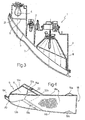
Fig. 4 is a perspective view of a detail of the lighting unit ofFig. 1 ; -
Fig. 5 is a front elevation of the detail ofFig. 4 ; -
Fig. 6 is a top plan view of the detail ofFig. 4 ; -
Fig. 7 is a rear elevation of the detail ofFig. 4 . - In
Figs. 1 to 3 , a lighting unit comprising asupport housing 2, aparking light 3, anindicator light 4, light diffusion means 5 and light collimation means 6 is shown overall by 1. - The
lighting unit 1 further comprises an outer front lens 7 and afog lamp 8 which are known and not described in further detail. - The light diffusion means 5 are formed by an optical diffuser having a
smooth surface 5a and aprismatic surface 5b. - The light collimation means 6 are formed by a Fresnel lens member obtained in one piece, having a
smooth surface 6a and asurface 6b on which a group of Fresnel lens is obtained by moulding. - The
diffuser 5 and the Fresnellens member 6, at their respectivefirst ends Figs. 4 to 7 ) adapted to carry out the functions of light collimation and diffusion. - Moreover, with particular reference to
Figs. 4 and6 , thediffuser 5 and the Fresnellens member 6 are reciprocally disposed to form an acute angle with theirrespective surfaces braces 12a and 12b. - The
brace 12a extends rigidly between respectiveupper edges diffuser 5 and the Fresnellens member 6. - Similarly, the brace 12b extends between respective
lower edges diffuser 5 and the Fresnellens member 6. - The
braces 12a and 12b also bearrespective locking teeth - These
locking teeth projection 16 and ashoulder 17 of thesupport housing 2 in order to enable the snap-locking of theoptical device 9 on thishousing 2, as shown inFig. 2 . - In the vicinity of one of its
front ends 18, thediffuser 4 rigidly bears a pair oflugs upper edge 14a and the lower edge 16b and adapted to maintain theoptical device 9 in its operating position, as described below. - A
third lug 19c is obtained rigidly with theoptical device 9 and projects to the rear from anedge 20 of this device at the junction of thefirst ends optical diffuser 5 and the Fresnellens member 6. - In operation, the
lug 19c is inserted in acorresponding housing 21 provided in thesupport housing 2. - The
braces 12a and 12b are provided in a longitudinal position such that they extend from asecond end 22 of the Fresnellens member 6 to an intermediate portion of thediffuser 5. - When the
optical device 9 is in its operating position, theoptical diffuser 5 is disposed in front of theparking light 3 and theindicator light 4, while the Fresnellens member 6 is interposed between theindicator light 4 and theoptical diffuser 5. - The optical effect obtained in this way is twofold.
- The
diffuser 5, which intercepts the light beams generated both by theparking light 3 and by theindicator light 4, makes these latter more comparable. - Moreover, the Fresnel
lens member 6 is adapted to mask, to an external observer, the presence of the coloured lamp of theindicator light 4. - It will be appreciated that modifications and variations not departing from the scope of protection of the present invention may be made to the
lighting unit 1. - In particular, the
optical device 9 may be modified such that thediffuser 5 extends so as also to cover the front of a headlamp that may be disposed adjacent to theparking light 3 or theindicator light 4. - Moreover, use may be made of optical diffusers differing from that described and comprising, for instance, a surface on which microprisms or holograms are obtained in place of the
prismatic surface 5b. - It will lastly be appreciated that the lugs and locking teeth for the snap-locking of the
optical device 9 on thehousing 2 may differ from what has been described above in terms of their number, shape and arrangement.
Claims (4)
- A multiple lighting unit (1), in particular for a vehicle, comprising at least one support housing (2), a first lighting device, provided with light diffusion means (5), in particular a parking light (3), a second lighting device, provided with light collimation means (6), in particular an indicator light (4), and an outer lens (7), the light diffusion means (5) being formed by an optical diffuser (5) disposed in front of at least the first (3) and second (4) lighting devices and the light collimation means (6) being formed by a Fresnel lens member interposed between the second lighting device (4) and the optical diffusers (5), wherein the Fresnel lens member (6) and the optical diffuser (5) are connected rigidly to form a single component, in order to form an optical device (9) adapted to carry out the functions of light collimation and diffusion; wherein the optical diffuser (5) and the Fresnel lens (6) member are reciprocally connected by their respective first ends (10, 11) in order to form an acute angle between one another, characterised in that the optical diffuser (5) and the Fresnel lens member (6) comprise respective smooth surfaces (5a, 6a), the optical diffuser (5) comprising a second prismatic surface (5b), the Fresnel lens member (6) comprising a surface bearing a group of Fresnel lenses (6b) and the first smooth surfaces (5a, 6a) being disposed to face one another.
- A lighting unit (1) as claimed in claim 1, characterised in that the optical device comprises means for snap-locking (15a, 15b) on the support housing (2).
- A lighting unit (1) as claimed in any one of the preceding claims, characterised in that the optical diffuser (5) and the Fresnel lens member (6) are further connected by a first and a second brace (12a, 12b), the first brace (12a) extending rigidly between respective upper edges (13a, 14a) and the second brace extending rigidly between respective lower edges (13b, 14b) of the optical diffuser (5) and the Fresnel lens (6) member.
- A lighting unit (1) as claimed in claim 3, characterised in that the first and second braces (12a, 12b) each rigidly bear at least one locking tooth (15a, 15b) obtained transversely thereon, the optical diffuser (5) bearing a first and a second locking lug (19a, 19b) obtained rigidly in the vicinity of a second end of the optical diffuser (5) and projecting internally respectively from the upper edge (14a) and the lower edge (14b) of the optical diffuser (5), a third locking lug (19c) obtained rigidly with the optical device projecting to the rear from the first ends of the optical diffuser (5) and the Fresnel lens member (6).
Priority Applications (1)
| Application Number | Priority Date | Filing Date | Title |
|---|---|---|---|
| DE69936330T DE69936330T3 (en) | 1998-10-14 | 1999-10-13 | Simplified construction for a vehicle lighting device |
Applications Claiming Priority (2)
| Application Number | Priority Date | Filing Date | Title |
|---|---|---|---|
| IT1998MI002210A IT1302671B1 (en) | 1998-10-14 | 1998-10-14 | SIMPLIFIED CONSTRUCTION OPTICAL DEVICE, IN PARTICULAR FOR A VEHICLE. |
| ITMI982210 | 1998-10-14 |
Publications (3)
| Publication Number | Publication Date |
|---|---|
| EP0993989A1 EP0993989A1 (en) | 2000-04-19 |
| EP0993989B1 EP0993989B1 (en) | 2007-06-20 |
| EP0993989B2 true EP0993989B2 (en) | 2012-03-28 |
Family
ID=11380870
Family Applications (1)
| Application Number | Title | Priority Date | Filing Date |
|---|---|---|---|
| EP99120394A Expired - Lifetime EP0993989B2 (en) | 1998-10-14 | 1999-10-13 | Lighting device of simplified construction, in particular for a vehicle |
Country Status (3)
| Country | Link |
|---|---|
| EP (1) | EP0993989B2 (en) |
| DE (1) | DE69936330T3 (en) |
| IT (1) | IT1302671B1 (en) |
Families Citing this family (3)
| Publication number | Priority date | Publication date | Assignee | Title |
|---|---|---|---|---|
| FR2809061B1 (en) * | 2000-05-16 | 2002-12-06 | Ecia Equip Composants Ind Auto | OPTICAL BLOCK FOR MOTOR VEHICLE, CORRESPONDING FRONT PANEL AND FRONT BLOCK |
| FR2965328B1 (en) * | 2010-09-24 | 2016-03-25 | Valeo Vision | METHOD FOR MANUFACTURING A COMPLEX PART OF A LIGHTING AND / OR SIGNALING DEVICE |
| DE102015115128B4 (en) * | 2015-09-09 | 2023-05-11 | HELLA GmbH & Co. KGaA | Lighting device for vehicles |
Citations (5)
| Publication number | Priority date | Publication date | Assignee | Title |
|---|---|---|---|---|
| DE1980059U (en) † | 1967-06-20 | 1968-02-29 | Westfaelische Metall Ind K G H | SINAL LIGHT FOR MOTOR VEHICLES. |
| DE3305218A1 (en) † | 1983-02-16 | 1984-08-16 | Westfälische Metall Industrie KG Hueck & Co, 4780 Lippstadt | Multi-chamber light for motor vehicles |
| JPH092142A (en) † | 1995-06-23 | 1997-01-07 | Stanley Electric Co Ltd | Lamp tool for vehicle |
| JPH0999777A (en) † | 1995-08-03 | 1997-04-15 | Koito Mfg Co Ltd | Vehicular marker lamp |
| EP0869312A2 (en) † | 1997-04-04 | 1998-10-07 | Britax Vega Limited | Vehicle signal lamp |
Family Cites Families (3)
| Publication number | Priority date | Publication date | Assignee | Title |
|---|---|---|---|---|
| JPH01235101A (en) * | 1988-03-16 | 1989-09-20 | Koito Mfg Co Ltd | Lighting fixture for vehicle |
| FR2727660A1 (en) * | 1994-12-06 | 1996-06-07 | Axo Scintex Cie Equip Automobi | TAIL LIGHTS OF MOTOR VEHICLES |
| FR2733950B1 (en) * | 1995-05-11 | 1997-08-01 | Valeo Vision | SIGNAL LIGHT COMPRISING A SEALING THROAT |
-
1998
- 1998-10-14 IT IT1998MI002210A patent/IT1302671B1/en active IP Right Grant
-
1999
- 1999-10-13 DE DE69936330T patent/DE69936330T3/en not_active Expired - Lifetime
- 1999-10-13 EP EP99120394A patent/EP0993989B2/en not_active Expired - Lifetime
Patent Citations (5)
| Publication number | Priority date | Publication date | Assignee | Title |
|---|---|---|---|---|
| DE1980059U (en) † | 1967-06-20 | 1968-02-29 | Westfaelische Metall Ind K G H | SINAL LIGHT FOR MOTOR VEHICLES. |
| DE3305218A1 (en) † | 1983-02-16 | 1984-08-16 | Westfälische Metall Industrie KG Hueck & Co, 4780 Lippstadt | Multi-chamber light for motor vehicles |
| JPH092142A (en) † | 1995-06-23 | 1997-01-07 | Stanley Electric Co Ltd | Lamp tool for vehicle |
| JPH0999777A (en) † | 1995-08-03 | 1997-04-15 | Koito Mfg Co Ltd | Vehicular marker lamp |
| EP0869312A2 (en) † | 1997-04-04 | 1998-10-07 | Britax Vega Limited | Vehicle signal lamp |
Also Published As
| Publication number | Publication date |
|---|---|
| EP0993989A1 (en) | 2000-04-19 |
| IT1302671B1 (en) | 2000-09-29 |
| DE69936330D1 (en) | 2007-08-02 |
| ITMI982210A1 (en) | 2000-04-14 |
| ITMI982210A0 (en) | 1998-10-14 |
| EP0993989B1 (en) | 2007-06-20 |
| DE69936330T3 (en) | 2012-08-09 |
| DE69936330T2 (en) | 2008-02-21 |
Similar Documents
| Publication | Publication Date | Title |
|---|---|---|
| CN112074687B (en) | Projection type headlamp | |
| US20080186725A1 (en) | Headlamp For Vehicles | |
| US9671078B2 (en) | Lighting unit for a motor vehicle | |
| JP3542113B2 (en) | Multi-eye lighting | |
| US7527404B2 (en) | Lighting and/or signalling apparatus for a motor vehicle | |
| EP2769879B1 (en) | Lighting apparatus | |
| EP0993989B2 (en) | Lighting device of simplified construction, in particular for a vehicle | |
| WO2011151352A1 (en) | External rear-view mirror assembly having a housing comprising a circuit board supporting a plurality of light emitting diodes | |
| CN110836355B (en) | Lighting system for a vehicle | |
| JP4666174B2 (en) | Vehicle lighting | |
| CZ290408B6 (en) | Car lamp with a hologram | |
| EP3540295B1 (en) | Vehicle headlamp assembly | |
| CN220707136U (en) | Dual function optical system for illuminating fender | |
| JPH0364962B2 (en) | ||
| JP6324017B2 (en) | Vehicle lamp | |
| CZ2018107A3 (en) | Vehicle lighting equipment | |
| CN116221649A (en) | Dual function optical system for illuminating fender | |
| JP6186844B2 (en) | Vehicle lighting | |
| CN112334702B (en) | Configurable vehicle lighting device with uniform appearance | |
| JPH07230706A (en) | Marker lamp for car | |
| JP2860136B2 (en) | Inner lens for vehicle signal lights | |
| WO2023189960A1 (en) | Vehicle lamp | |
| JP6817044B2 (en) | Vehicle headlights | |
| KR19980064217A (en) | Car lamp | |
| ITRM980555A1 (en) | LIGHTING OR SIGNALING DEVICE WITH OPTICAL LIGHT DUCT MAINLY FOR AUTOMOTIVE VEHICLES |
Legal Events
| Date | Code | Title | Description |
|---|---|---|---|
| PUAI | Public reference made under article 153(3) epc to a published international application that has entered the european phase |
Free format text: ORIGINAL CODE: 0009012 |
|
| AK | Designated contracting states |
Kind code of ref document: A1 Designated state(s): DE ES FR GB |
|
| AX | Request for extension of the european patent |
Free format text: AL;LT;LV;MK;RO;SI |
|
| 17P | Request for examination filed |
Effective date: 20000316 |
|
| AKX | Designation fees paid |
Free format text: DE ES FR GB |
|
| GRAP | Despatch of communication of intention to grant a patent |
Free format text: ORIGINAL CODE: EPIDOSNIGR1 |
|
| GRAS | Grant fee paid |
Free format text: ORIGINAL CODE: EPIDOSNIGR3 |
|
| GRAA | (expected) grant |
Free format text: ORIGINAL CODE: 0009210 |
|
| AK | Designated contracting states |
Kind code of ref document: B1 Designated state(s): DE ES FR GB |
|
| REG | Reference to a national code |
Ref country code: GB Ref legal event code: FG4D |
|
| REF | Corresponds to: |
Ref document number: 69936330 Country of ref document: DE Date of ref document: 20070802 Kind code of ref document: P |
|
| ET | Fr: translation filed | ||
| PG25 | Lapsed in a contracting state [announced via postgrant information from national office to epo] |
Ref country code: ES Free format text: LAPSE BECAUSE OF FAILURE TO SUBMIT A TRANSLATION OF THE DESCRIPTION OR TO PAY THE FEE WITHIN THE PRESCRIBED TIME-LIMIT Effective date: 20071001 |
|
| PLBI | Opposition filed |
Free format text: ORIGINAL CODE: 0009260 |
|
| PLAX | Notice of opposition and request to file observation + time limit sent |
Free format text: ORIGINAL CODE: EPIDOSNOBS2 |
|
| 26 | Opposition filed |
Opponent name: VALEO VISION Effective date: 20080320 |
|
| GBPC | Gb: european patent ceased through non-payment of renewal fee |
Effective date: 20071013 |
|
| PLAF | Information modified related to communication of a notice of opposition and request to file observations + time limit |
Free format text: ORIGINAL CODE: EPIDOSCOBS2 |
|
| PLBB | Reply of patent proprietor to notice(s) of opposition received |
Free format text: ORIGINAL CODE: EPIDOSNOBS3 |
|
| PG25 | Lapsed in a contracting state [announced via postgrant information from national office to epo] |
Ref country code: GB Free format text: LAPSE BECAUSE OF NON-PAYMENT OF DUE FEES Effective date: 20071013 |
|
| PUAH | Patent maintained in amended form |
Free format text: ORIGINAL CODE: 0009272 |
|
| STAA | Information on the status of an ep patent application or granted ep patent |
Free format text: STATUS: PATENT MAINTAINED AS AMENDED |
|
| 27A | Patent maintained in amended form |
Effective date: 20120328 |
|
| AK | Designated contracting states |
Kind code of ref document: B2 Designated state(s): DE ES FR GB |
|
| REG | Reference to a national code |
Ref country code: DE Ref legal event code: R102 Ref document number: 69936330 Country of ref document: DE Effective date: 20120328 |
|
| REG | Reference to a national code |
Ref country code: DE Ref legal event code: R082 Ref document number: 69936330 Country of ref document: DE Representative=s name: DREISS PATENTANWAELTE PARTG MBB, DE Ref country code: DE Ref legal event code: R082 Ref document number: 69936330 Country of ref document: DE Representative=s name: DREISS PATENTANWAELTE PARTNERSCHAFT, DE |
|
| REG | Reference to a national code |
Ref country code: FR Ref legal event code: PLFP Year of fee payment: 18 |
|
| REG | Reference to a national code |
Ref country code: FR Ref legal event code: PLFP Year of fee payment: 19 |
|
| REG | Reference to a national code |
Ref country code: FR Ref legal event code: PLFP Year of fee payment: 20 |
|
| PGFP | Annual fee paid to national office [announced via postgrant information from national office to epo] |
Ref country code: FR Payment date: 20180920 Year of fee payment: 20 |
|
| PGFP | Annual fee paid to national office [announced via postgrant information from national office to epo] |
Ref country code: DE Payment date: 20180819 Year of fee payment: 20 |
|
| REG | Reference to a national code |
Ref country code: DE Ref legal event code: R071 Ref document number: 69936330 Country of ref document: DE |