EP0993869A2 - Pipetting device - Google Patents
Pipetting device Download PDFInfo
- Publication number
- EP0993869A2 EP0993869A2 EP99120448A EP99120448A EP0993869A2 EP 0993869 A2 EP0993869 A2 EP 0993869A2 EP 99120448 A EP99120448 A EP 99120448A EP 99120448 A EP99120448 A EP 99120448A EP 0993869 A2 EP0993869 A2 EP 0993869A2
- Authority
- EP
- European Patent Office
- Prior art keywords
- pipetting
- micropumps
- micropump
- pipetting device
- channel
- Prior art date
- Legal status (The legal status is an assumption and is not a legal conclusion. Google has not performed a legal analysis and makes no representation as to the accuracy of the status listed.)
- Granted
Links
Images
Classifications
-
- B—PERFORMING OPERATIONS; TRANSPORTING
- B01—PHYSICAL OR CHEMICAL PROCESSES OR APPARATUS IN GENERAL
- B01L—CHEMICAL OR PHYSICAL LABORATORY APPARATUS FOR GENERAL USE
- B01L3/00—Containers or dishes for laboratory use, e.g. laboratory glassware; Droppers
- B01L3/02—Burettes; Pipettes
- B01L3/021—Pipettes, i.e. with only one conduit for withdrawing and redistributing liquids
- B01L3/0213—Accessories for glass pipettes; Gun-type pipettes, e.g. safety devices, pumps
-
- G—PHYSICS
- G01—MEASURING; TESTING
- G01N—INVESTIGATING OR ANALYSING MATERIALS BY DETERMINING THEIR CHEMICAL OR PHYSICAL PROPERTIES
- G01N35/00—Automatic analysis not limited to methods or materials provided for in any single one of groups G01N1/00 - G01N33/00; Handling materials therefor
- G01N2035/00178—Special arrangements of analysers
- G01N2035/00237—Handling microquantities of analyte, e.g. microvalves, capillary networks
Definitions
- the present invention relates to a pipetting device with at least one pipetting channel and with at least one interacting with the pipetting channel Pumping device for suctioning and dispensing Liquid.
- Such pipetting devices are especially known as Multi-channel pipettes used to a variety of on Supply the samples arranged in the titer plates at the same time to be able to. All pipettes are from one common drive member via a piston and a Air cushions are actuated and point the pipetting channels interchangeable pipette tips, which the the to be dosed Record volume and can be exchanged to to avoid the spread of contamination. The Contamination of the pipette channels themselves is caused by the Avoid air pockets. In the known devices is particularly disadvantageous that the pipetting volume due to the stroke of the piston even with the smallest Piston diameters cannot be minimized at will. This problem exists with both directly operated as also with air-cushion pipettes.
- the object of the invention is a pipetting device propose with the arbitrarily small volumes with a small space requirement of the pump device can be pipetted.
- micropumps open up the Possibility to convey very small volumes and this also set exactly.
- the delivery volume during the suction process is the delivery volume during the suction process as well exactly adjustable during the dosing process.
- Both promote Pump the medium in opposite directions in only one direction and can be used accordingly just be set up. Because of their low They can also be used without space without enlargement of the construction volume compared to conventional pipettes accommodate
- the micropump can be piezoelectric, electromagnetic or driven electrostatically. With the electrostatic Repulsion forces become different Charges used.
- an air cushion in the pipetting channel and the pumping device arranged that a contact of the to be promoted Prevents medium with the micropumps.
- the micropumps are not contaminated and when using pipetting tips remain the pipetting channels from that medium to be funded untouched.
- the one micropump with its pressure connection and the other micropump with its suction connection with the Environment is in connection with the Air cushions in the micropumps themselves only convey air the two micropumps with their respective connections with the environment for aspirating or dispensing Air related.
- the suction and pressure sides also advantageously have Connections of the micropumps check valves to the opposite flow direction in both micropumps to force.
- the two micropumps can be activated independently of each other, so that the a micropump sucked volume of the medium from the Volume delivered by the other micropump will not have to be identical. It can therefore be multiple pipetting operations in a single suction stroke perform one after the other.
- the two micropumps each advantageously a constant stroke so that both micropumps on have a defined pump volume and the pumped or The volume delivered is defined by the number of strokes is.
- each pipetting channel is preferably one Pump device assigned. That is the possibility given the delivery volume at each individual pipetting channel to define independently and thus for example Series experiments with different titration volumes in perform one work step.
- the micropumps are advantageously designed as diaphragm pumps, since it takes up a minimum of space with the largest Have functional reliability.
- the membrane can rubber-elastic materials, e.g. Polymers, but also consist of metallic or ceramic materials.
- the metering device an electronic control device for actuating the electric drive of each micropump with which on the one hand, the two assigned to a pipetting channel Micropumps checked, on the other hand the micropumps different pipetting channels independently of each other can be operated.
- the invention is based on an exemplary embodiment described.
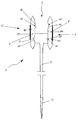
- the drawing shows schematically a pipetting device 1, consisting of a pipetting channel 2 and one Pump device 3. On the lower end of the pipetting channel 2, a pipette tip 4 is detachably attached.
- the pump device 3 consists of a first micropump 5 and a second micropump 6.
- the two micropumps 5 and 6 each have a pump chamber 7, 8 and a suction side connection 9, 12 and one pressure side each Connection 10.11 on.
- the connections 9,10,11,12 are protected against kickback with simple valve flaps 15, 16, 17, 18.
- the micropumps 5 and 6 are with each a connection 9, 11 with the pipetting channel 2 and their respective second connection 10, 12 with the environment in Connection. So the micropump 5 on the suction side Pipetting channel 2 connected and on the pressure side the surrounding area while the other micropump 6 on the pressure side with the pipetting channel 2 and on the suction side with related to the environment.
- the micropumps are 5.6 as diaphragm pumps, each with a diaphragm 19.20 made of a rigid material.
- the membranes 19, 20 are each directly connected to a piezo actuator 13 or 14 connected.
- a piezoelectric actuator 13 Micropump 5 via control electronics, not shown controlled so that the volume of the Pump chamber 7 enlarged, air from pipetting channel 2 with port 9 open and port 10 closed is sucked into the pump chamber 7 of the micropump 5 and due to the negative pressure created in the pipetting channel 2 medium to be conveyed enters the pipette tip 4.
- a piezoelectric actuator 14 is the Micropump 6 actuated so that the volume of the pumping chamber 8 enlarged, the pressure side port 11 closed remains and ambient air through the suction side Port 12 flows into the pump chamber 8.
- the stroke of the Actuator 13 can be controlled electronically so that a freely definable volume is sucked in. By setting the stroke rate can be the total volume for one Dosing process can be varied.
- the two actuators 13 and 14 actuated so that the volumes of the pump chamber 7 and 8 reduce, with the pump chamber 7 from Micropump 5 air via the pressure-side connection 10 is released and the suction-side connection 9 is closed is.
- the air from the pump chamber 8 of the micropump 6 becomes via the pressure side connection 11 of the micropump 6 in pressed the pipetting channel 2. It is in the Pipette tip 4 located medium corresponding to the Stroke volume of the micropump 6, possibly several times according to the set number of strokes.
- the void volume between the two micropumps accordingly be interpreted. If necessary, the drive of the pump not working at the work cycle of the other Pump can be reversed to close the valve flaps to ensure.
Abstract
Description
Die vorliegende Erfindung betrifft eine Pipettiervorrichtung mit zumindest einem Pipettierkanal und mit zumindest einer mit dem Pipettierkanal zusammenwirkenden Pumpeinrichtung zum Ansaugen und dosierten Abgeben von Flüssigkeit.The present invention relates to a pipetting device with at least one pipetting channel and with at least one interacting with the pipetting channel Pumping device for suctioning and dispensing Liquid.
Solche Pipettiervorrichtungen besitzen in der Labortechnik ein breites Anwendungsgebiet. Für viele Nachweise, Analysen, Synthesen etc. ist eine exakte Zudosierung und/oder Entnahme von Flüssigkeiten in kleinen bis kleinsten Mengen notwendig. Wichtig ist dabei vor allem die Voreinstellbarkeit und die Reproduzierbarkeit des zudosierten Volumens sowie die Eignung zur Durchführung von Reihenversuchen.Such pipetting devices are used in laboratory technology a wide range of applications. For a lot of evidence, Analyzes, syntheses etc. is an exact addition and / or withdrawal of liquids in small to smallest quantities necessary. The most important thing is the presettability and the reproducibility of the metered volume and suitability for implementation of serial tests.
Solche Pipettiervorrichtungen werden insbesonders als Mehrkanalpipetten eingesetzt, um eine Vielzahl von auf Titerplatten angeordneten Proben gleichzeitig versorgen zu können. Dabei werden sämtliche Pipetten von einem gemeinsamen Antriebsglied über je einen Kolben und ein Luftpolster betätigt und weisen die Pipettierkanäle auswechselbare Pipettierspitzen aus, die das zu dosierende Volumen aufnehmen und ausgetauscht werden können, um das Verschleppen von Kontaminationen zu vermeiden. Die Kontamination der Pipettenkanäle selbst wird durch das Luftpolster vermieden. Bei den bekannten Vorrichtungen ist insbesondere von Nachteil, daß das Pipettiervolumen aufgrund des Hubwegs des Kolbens auch bei kleinsten Kolbendurchmessern nicht beliebig minimiert werden kann. Dieses Problem besteht sowohl bei direkt betriebenen wie auch bei Luftpolster-Pipetten.Such pipetting devices are especially known as Multi-channel pipettes used to a variety of on Supply the samples arranged in the titer plates at the same time to be able to. All pipettes are from one common drive member via a piston and a Air cushions are actuated and point the pipetting channels interchangeable pipette tips, which the the to be dosed Record volume and can be exchanged to to avoid the spread of contamination. The Contamination of the pipette channels themselves is caused by the Avoid air pockets. In the known devices is particularly disadvantageous that the pipetting volume due to the stroke of the piston even with the smallest Piston diameters cannot be minimized at will. This problem exists with both directly operated as also with air-cushion pipettes.
Der Erfindung liegt die Aufgabe zugrunde, eine Pipettiervorrichtung vorzuschlagen, mit der beliebig kleine Volumina bei zugleich geringem Raumbedarf der Pumpeinrichtung pipettiert werden können.The object of the invention is a pipetting device propose with the arbitrarily small volumes with a small space requirement of the pump device can be pipetted.
Diese Aufgabe wird bei einer Pipettiervorrichtung der eingangs genannten Art erfindungsgemäß dadurch gelöst, daß die Pumpeinrichtung aus zwei elektrisch betriebenen Mikropumpen mit jeweils einem saugseitigen und einem druckseitigen Anschluß besteht und daß die eine Mikropumpe saugseitig und die andere druckseitig mit dem Pipettierkanal in Verbindung steht.This task is carried out in a pipetting device solved at the outset according to the invention, that the pumping device consists of two electrically operated Micropumps with one suction side and one each pressure-side connection exists and that the one micropump suction side and the other pressure side with the Pipetting channel is connected.
Die in neuerer Zeit entwickelten Mikropumpen eröffnen die Möglichkeit, sehr kleine Volumina zu fördern und diese zudem genau einzustellen. Mit der Anordnung von zwei Mikropumpen, von denen die eine saugseitig und die andere druckseitig mit dem Pipettierkanal in Verbindung steht, ist das Fördervolumen sowohl beim Ansaugvorgang als auch beim Dosiervorgang exakt einstellbar. Dabei fördern beide Pumpen das Medium jeweils gegenläufig in nur eine Richtung und können hinsichtlich ihrer Anschlüsse entsprechend einfach aufgebaut sein. Aufgrund ihres geringen Raumbedarfs lassen sie sich auch problemlos ohne Vergrösserung des Bauvolumens gegenüber herkömmlichen Pipetten unterbringenThe recently developed micropumps open up the Possibility to convey very small volumes and this also set exactly. With the arrangement of two Micropumps, one on the suction side and the other is connected to the pipetting channel on the pressure side, is the delivery volume during the suction process as well exactly adjustable during the dosing process. Both promote Pump the medium in opposite directions in only one direction and can be used accordingly just be set up. Because of their low They can also be used without space without enlargement of the construction volume compared to conventional pipettes accommodate
Die Mikropumpe kann piezoelektrisch, elektromagnetisch oder elektrostatisch angetrieben werden. Bei dem elektrostatischen Antrieb werden Abstoßungskräfte unterschiedlicher Ladungen genutzt.The micropump can be piezoelectric, electromagnetic or driven electrostatically. With the electrostatic Repulsion forces become different Charges used.
In vorteilhafter Ausführung ist zwischen der Flüssigkeit in dem Pipettierkanal und der Pumpeinrichtung ein Luftpolster angeordnet, das einen Kontakt des zu fördernden Mediums mit den Mikropumpen verhindert. Die Mikropumpen werden nicht kontaminiert und bei Verwendung von Pipettierspitzen bleiben auch die Pipettierkanäle von dem zu fördernden Medium unberührt.In an advantageous embodiment is between the liquid an air cushion in the pipetting channel and the pumping device arranged that a contact of the to be promoted Prevents medium with the micropumps. The micropumps are not contaminated and when using pipetting tips remain the pipetting channels from that medium to be funded untouched.
Dadurch, daß die eine Mikropumpe mit ihrem Druckanschluß und die andere Mikropumpe mit ihrem Sauganschluß mit der Umgebung in Verbindung steht, wird in Verbindung mit dem Luftpolster in den Mikropumpen selbst nur Luft gefördert, wobei die beiden Mikropumpen mit ihren jeweiligen Anschlüssen mit der Umgebung zum Ansaugen oder Abgeben von Luft in Verbindung stehen.Because the one micropump with its pressure connection and the other micropump with its suction connection with the Environment is in connection with the Air cushions in the micropumps themselves only convey air the two micropumps with their respective connections with the environment for aspirating or dispensing Air related.
Weiterhin vorteilhaft weisen die saug- und druckseitigen Anschlüsse der Mikropumpen Rückschlagventile auf, um die jeweils gegenläufige Fließrichtung in beiden Mikropumpen zu erzwingen. The suction and pressure sides also advantageously have Connections of the micropumps check valves to the opposite flow direction in both micropumps to force.
In bevorzugter Ausführung sind die beiden Mikropumpen unabhängig voneinander aktivierbar, so daß das von der einen Mikropumpe angesaugte Volumen des Mediums von dem Volumen, das von der anderen Mikropumpe dosiert abgegeben wird, nicht identisch sein muß. Es lassen sich folglich bei einem einzigen Saughub mehrere Pipettiervorgänge nacheinander durchführen.In a preferred embodiment, the two micropumps can be activated independently of each other, so that the a micropump sucked volume of the medium from the Volume delivered by the other micropump will not have to be identical. It can therefore be multiple pipetting operations in a single suction stroke perform one after the other.
In weiterhin vorteilhafter Ausführung ist jeweils nur einer der mit dem Pipettierkanal in Verbindung stehenden Anschlüsse geöffnet, während der zweite in dieser Zeit geschlossen bleibt. Dadurch wird verhindert, daß Luft in die passive Pumpe einströmt oder aus dessen Pumpkammer angesaugt wird, da dies die dosierte Förderung beeinträchtigen würde.In a further advantageous embodiment is only one of those connected to the pipetting channel Connections opened during the second at that time remains closed. This will prevent air from entering the passive pump flows in or from its pump chamber is sucked in, as this affects the metered delivery would.
Weiterhin weisen die zwei Mikropumpen mit Vorteil jeweils einen konstanten Hub auf, so daß beide Mikropumpen ein definiertes Pumpvolumen aufweisen und das geförderte bzw. abgegebene Volumen über die Anzahl der Hübe definiert ist.Furthermore, the two micropumps each advantageously a constant stroke so that both micropumps on have a defined pump volume and the pumped or The volume delivered is defined by the number of strokes is.
Bei Dosiervorrichtungen mit mehreren Pipettierkanälen, beispielsweise für den Einsatz in Verbindung mit Titerplatten, ist vorzugsweise jedem Pipettierkanal eine Pumpeinrichtung zugeordnet. Damit ist die Möglichkeit gegeben, das Fördervolumen an jedem einzelnen Pipettierkanal unabhängig zu definieren und somit beispielsweise Reihenversuche mit unterschiedlichen Titriervolumina in einem Arbeitsschritt durchzuführen.With dosing devices with several pipetting channels, for example for use in conjunction with titer plates, each pipetting channel is preferably one Pump device assigned. That is the possibility given the delivery volume at each individual pipetting channel to define independently and thus for example Series experiments with different titration volumes in perform one work step.
Mit Vorteil sind die Mikropumpen als Membranpumpen ausgebildet, da sie einen minimalen Platzbedarf bei größter Funktionssicherheit aufweisen. Die Membran kann aus gummielastischen Werkstoffen, z.B. Polymeren, aber auch aus metallischen oder keramischen Werkstoffen bestehen.The micropumps are advantageously designed as diaphragm pumps, since it takes up a minimum of space with the largest Have functional reliability. The membrane can rubber-elastic materials, e.g. Polymers, but also consist of metallic or ceramic materials.
In bevorzugter Ausführung weist die Dosiervorrichtung eine elektronische Steuereinrichtung zur Betätigung des elektrischen Antriebs jeder Mikropumpe auf, mit der einerseits die jeweils zwei einem Pipettierkanal zugeordneten Mikropumpen kontrolliert, andererseits die Mikropumpen verschiedener Pipettierkanäle unabhängig voneinander betätigt werden können.In a preferred embodiment, the metering device an electronic control device for actuating the electric drive of each micropump with which on the one hand, the two assigned to a pipetting channel Micropumps checked, on the other hand the micropumps different pipetting channels independently of each other can be operated.
Nachstehend ist die Erfindung anhand eines Ausführungsbeispiels beschrieben.The invention is based on an exemplary embodiment described.
Die Zeichnung zeigt schematisch eine Pipettiervorrichtung
1, bestehend aus einem Pipettierkanal 2 und einer
Pumpeinrichtung 3. Auf das untere Ende des Pipettierkanals
2 ist eine Pipettierspitze 4 abnehmbar aufgesteckt.The drawing shows schematically a
In dem Pipettierkanal 2 sowie der Pumpeinrichtung 3
befindet sich Luft. Das anzusaugende und zu dosierende
Medium nur mit der Pipettierspitze 4 in Berührung kommt.
Bei einem Austausch der Pipettierspitze 4 ist die Pipettiervorrichtung
1 ohne weitere Reinigung sofort wieder
für andere Medien einsatzbereit.In the pipetting
Die Pumpeinrichtung 3 besteht aus einer ersten Mikropumpe
5 und einer zweiten Mikropumpe 6. Die beiden Mikropumpen
5 und 6 weisen jeweils eine Pumpkammer 7, 8 und jeweils
einen saugseitigen Anschluß 9,12 und jeweils einen druckseitigen
Anschluß 10,11 auf. Die Anschlüsse 9,10,11,12
sind mit einfachen Ventilklappen 15,16,17,18 rückschlaggesichert.
Die Mikropumpen 5 und 6 stehen mit jeweils
einem Anschluß 9,11 mit dem Pipettierkanal 2 und mit
ihrem jeweils zweiten Anschluß 10, 12 mit der Umgebung in
Verbindung. So ist die Mikropumpe 5 saugseitig an den
Pipettierkanal 2 angeschlossen und steht druckseitig mit
der Umgebung in Verbindung, während die andere Mikropumpe
6 druckseitig mit dem Pipettierkanal 2 und saugseitig mit
der Umgebung in Verbindung steht.The
Bei dem gezeigten Ausführungsbeispiel sind die Mikropumpen
5,6 als Membranpumpen mit je einer Membran 19,20
aus einem starren Werkstoff ausgebildet. Die Membranen
19,20 sind unmittelbar mit je einem Piezoaktor 13 bzw. 14
verbunden.In the embodiment shown, the micropumps are
5.6 as diaphragm pumps, each with a diaphragm 19.20
made of a rigid material. The
Beim Ansaugen des zu dosierenden Mediums in die Pipettierspitze
4 wird ein piezoelektrischer Aktor 13 der
Mikropumpe 5 über eine nicht dargestellte Steuerungselektronik
so angesteuert, daß sich das Volumen der
Pumpkammer 7 vergrößert, Luft aus dem Pipettierkanal 2
bei geöffnetem Anschluß 9 und geschlossenem Anschluß 10
in die Pumpkammer 7 der Mikropumpe 5 gesaugt wird und
durch den im Pipettierkanal 2 entstehenden Unterdruck das
zu fördernde Medium in die Pipettierspitze 4 eintritt.
Gleichzeitig wird ein piezoelektrischer Aktor 14 der
Mikropumpe 6 so betätigt, daß sich das Volumen der Pumpkammer
8 vergrößert, der druckseitige Anschluß 11 geschlossen
bleibt und Umgebungsluft durch den saugseitigen
Anschluß 12 in die Pumpkammer 8 strömt. Der Hub des
Aktors 13 kann elektronisch so gesteuert werden, daß ein
frei festlegbares Volumen angesaugt wird. Durch Einstellung
der Hubzahl kann das Gesamtvolumen für einen
Dosiervorgang variiert werden. When aspirating the medium to be dosed into the
Beim Abgeben des Fördermediums werden die beiden Aktoren
13 und 14 so betätigt, daß sich die Volumina der Pumpkammer
7 und 8 verringern, wobei aus der Pumpkammer 7 der
Mikropumpe 5 Luft über den druckseitigen Anschluß 10
abgegeben wird und der saugseitige Anschluß 9 geschlossen
ist. Die Luft aus der Pumpkammer 8 der Mikropumpe 6 wird
über den druckseitigen Anschluß 11 der Mikropumpe 6 in
den Pipettierkanal 2 gedrückt. Dabei wird das in der
Pipettierspitze 4 befindliche Medium entsprechend dem
Hubvolumen der Mikropumpe 6, gegebenenfalls mehrfach
entsprechend der eingestellten Hubzahl, abgegeben.When the delivery medium is dispensed, the two
Um ein ungewolltes Überströmen des Pumpvolumens von einer in die andere Mikropumpe zu vermeiden, muß das Hohlraumvolumen zwischen den beiden Mikropumpen entsprechend ausgelegt werden. Gegebenenfalls kann der Antrieb der nicht arbeitenden Pumpe beim Arbeitstakt der anderen Pumpe umgekehrt werden, um einen Verschluß der Ventilklappen zu gewährleisten.To prevent an unwanted overflow of the pump volume from one To avoid entering the other micropump, the void volume between the two micropumps accordingly be interpreted. If necessary, the drive of the pump not working at the work cycle of the other Pump can be reversed to close the valve flaps to ensure.
Claims (11)
Applications Claiming Priority (2)
| Application Number | Priority Date | Filing Date | Title |
|---|---|---|---|
| DE19847869A DE19847869A1 (en) | 1998-10-17 | 1998-10-17 | Pipetting device |
| DE19847869 | 1998-10-17 |
Publications (3)
| Publication Number | Publication Date |
|---|---|
| EP0993869A2 true EP0993869A2 (en) | 2000-04-19 |
| EP0993869A3 EP0993869A3 (en) | 2002-05-29 |
| EP0993869B1 EP0993869B1 (en) | 2005-01-19 |
Family
ID=7884763
Family Applications (1)
| Application Number | Title | Priority Date | Filing Date |
|---|---|---|---|
| EP99120448A Expired - Lifetime EP0993869B1 (en) | 1998-10-17 | 1999-10-14 | Pipetting device |
Country Status (3)
| Country | Link |
|---|---|
| EP (1) | EP0993869B1 (en) |
| AT (1) | ATE287293T1 (en) |
| DE (2) | DE19847869A1 (en) |
Cited By (5)
| Publication number | Priority date | Publication date | Assignee | Title |
|---|---|---|---|---|
| EP1150013A3 (en) * | 2000-04-28 | 2002-09-18 | Agilent Technologies, Inc. (a Delaware corporation) | Microfluidic pumping |
| WO2004018103A1 (en) * | 2002-08-22 | 2004-03-04 | Fraunhofer-Gesellschaft zur Förderung der angewandten Forschung e.V. | Pipetting device and method for operating a pipetting device |
| WO2005035126A1 (en) * | 2003-09-26 | 2005-04-21 | Hirschmann Laborgeräte GmbH & Co. KG | Multi-channel pipette device |
| WO2007140830A1 (en) * | 2006-06-07 | 2007-12-13 | Henkel Ag & Co. Kgaa | Metering apparatus for flowable compositions |
| CN110898869A (en) * | 2018-09-18 | 2020-03-24 | 埃佩多夫股份公司 | Holding device for holding a pipetting container on a pipetting device |
Families Citing this family (2)
| Publication number | Priority date | Publication date | Assignee | Title |
|---|---|---|---|---|
| DE102006034245C5 (en) * | 2006-07-21 | 2014-05-28 | Stratec Biomedical Systems Ag | Positioning device for positioning pipettes |
| CN106944167A (en) * | 2017-04-07 | 2017-07-14 | 周肇梅 | A kind of use for laboratory dropper |
Citations (2)
| Publication number | Priority date | Publication date | Assignee | Title |
|---|---|---|---|---|
| EP0725267A2 (en) * | 1995-02-01 | 1996-08-07 | Forschungszentrum Rossendorf e.V. | Electrically controlled micro-pipette |
| EP0865824A1 (en) * | 1997-03-20 | 1998-09-23 | F. Hoffmann-La Roche Ag | Micromechanical pipetting device |
-
1998
- 1998-10-17 DE DE19847869A patent/DE19847869A1/en active Pending
-
1999
- 1999-10-14 AT AT99120448T patent/ATE287293T1/en not_active IP Right Cessation
- 1999-10-14 DE DE59911475T patent/DE59911475D1/en not_active Expired - Lifetime
- 1999-10-14 EP EP99120448A patent/EP0993869B1/en not_active Expired - Lifetime
Patent Citations (2)
| Publication number | Priority date | Publication date | Assignee | Title |
|---|---|---|---|---|
| EP0725267A2 (en) * | 1995-02-01 | 1996-08-07 | Forschungszentrum Rossendorf e.V. | Electrically controlled micro-pipette |
| EP0865824A1 (en) * | 1997-03-20 | 1998-09-23 | F. Hoffmann-La Roche Ag | Micromechanical pipetting device |
Non-Patent Citations (3)
| Title |
|---|
| GRAVESEN P ET AL: "MICROFLUIDICS - A REVIEW" JOURNAL OF MICROMECHANICS & MICROENGINEERING, NEW YORK, NY, US, Bd. 3, 1993, Seiten 168-182, XP000601274 ISSN: 0960-1317 * |
| LINNEMANN R ET AL: "A self-priming and bubble-tolerant piezoelectric silicon micropump for liquids and gases" MICRO ELECTRO MECHANICAL SYSTEMS, 1998. MEMS 98. PROCEEDINGS., THE ELEVENTH ANNUAL INTERNATIONAL WORKSHOP ON HEIDELBERG, GERMANY 25-29 JAN. 1998, NEW YORK, NY, USA,IEEE, US, 25. Januar 1998 (1998-01-25), Seiten 532-537, XP010270205 ISBN: 0-7803-4412-X * |
| ZENGERLE R ET AL: "A bidirectional silicon micropump" SENSORS AND ACTUATORS A, ELSEVIER SEQUOIA S.A., LAUSANNE, CH, Bd. 50, Nr. 1-2, August 1995 (1995-08), Seiten 81-86, XP004303517 ISSN: 0924-4247 * |
Cited By (6)
| Publication number | Priority date | Publication date | Assignee | Title |
|---|---|---|---|---|
| EP1150013A3 (en) * | 2000-04-28 | 2002-09-18 | Agilent Technologies, Inc. (a Delaware corporation) | Microfluidic pumping |
| WO2004018103A1 (en) * | 2002-08-22 | 2004-03-04 | Fraunhofer-Gesellschaft zur Förderung der angewandten Forschung e.V. | Pipetting device and method for operating a pipetting device |
| WO2005035126A1 (en) * | 2003-09-26 | 2005-04-21 | Hirschmann Laborgeräte GmbH & Co. KG | Multi-channel pipette device |
| WO2007140830A1 (en) * | 2006-06-07 | 2007-12-13 | Henkel Ag & Co. Kgaa | Metering apparatus for flowable compositions |
| CN110898869A (en) * | 2018-09-18 | 2020-03-24 | 埃佩多夫股份公司 | Holding device for holding a pipetting container on a pipetting device |
| CN110898869B (en) * | 2018-09-18 | 2022-09-20 | 埃佩多夫股份公司 | Holding device for holding a pipetting container on a pipetting device |
Also Published As
| Publication number | Publication date |
|---|---|
| EP0993869A3 (en) | 2002-05-29 |
| DE19847869A1 (en) | 2000-04-20 |
| DE59911475D1 (en) | 2005-02-24 |
| ATE287293T1 (en) | 2005-02-15 |
| EP0993869B1 (en) | 2005-01-19 |
Similar Documents
| Publication | Publication Date | Title |
|---|---|---|
| EP2576068B1 (en) | Device for transporting small volumes of a fluid, in particular a micropump or microvalve | |
| DE10344700A1 (en) | Multichannel pipetting | |
| DE19737173B4 (en) | micro-dosing system | |
| EP0725267B1 (en) | Electrically controlled micro-pipette | |
| EP1699560B1 (en) | Pipette tip, pipette device, pipette tip actuating device and pipetting method in the nanolitre range | |
| EP2205869A1 (en) | Membrane pump | |
| WO2011091943A1 (en) | Micro-fluidic component for manipulating a fluid, and microfluidic chip | |
| DE10337484A1 (en) | Microdosing device and method for the metered dispensing of liquids | |
| DE10010208C2 (en) | Microdosing device for the defined delivery of small, closed liquid volumes | |
| DE2628640A1 (en) | DEVICE FOR PIPETTING WITH CONSTANT VOLUME INCREMENTS | |
| DE102010038414A1 (en) | Pipetting device with throttle point in the pipetting channel | |
| EP0993869A2 (en) | Pipetting device | |
| DE4239464A1 (en) | Electrothermal static micro-pump with fluid-pressure-operated valve - drives liq. past resilient flap into outlet by expansion of vapour bubble generated by electric heating element | |
| EP1414575B1 (en) | Device for pipetting a liquid | |
| EP0672834B1 (en) | Micro fluid manipulator | |
| EP0668500A2 (en) | Chemical microanalyser | |
| EP1827695A1 (en) | Device for pumping fluids, method for production thereof and pipette with said device | |
| DE102013108948A1 (en) | Device for conveying liquids with the aid of a piezo drive device | |
| EP1036594B1 (en) | Multichannel droplet generator | |
| DE102005061629B4 (en) | Apparatus and method for transporting and forming compartments | |
| DE19611270A1 (en) | Micro-mixer for very small volumes of liquids or suspensions | |
| DE102007032951B4 (en) | Apparatus and method for supplying a liquid flow from at least two liquid sections into a measuring cell | |
| DE102016200960A1 (en) | pumping device | |
| EP3485974B1 (en) | Microdosing device for dosing minute fluid samples | |
| DE112019003200T5 (en) | Droplet dispenser |
Legal Events
| Date | Code | Title | Description |
|---|---|---|---|
| PUAI | Public reference made under article 153(3) epc to a published international application that has entered the european phase |
Free format text: ORIGINAL CODE: 0009012 |
|
| AK | Designated contracting states |
Kind code of ref document: A2 Designated state(s): AT BE CH CY DE DK ES FI FR GB GR IE IT LI LU MC NL PT SE |
|
| AX | Request for extension of the european patent |
Free format text: AL;LT;LV;MK;RO;SI |
|
| PUAL | Search report despatched |
Free format text: ORIGINAL CODE: 0009013 |
|
| AK | Designated contracting states |
Kind code of ref document: A3 Designated state(s): AT BE CH CY DE DK ES FI FR GB GR IE IT LI LU MC NL PT SE |
|
| AX | Request for extension of the european patent |
Free format text: AL;LT;LV;MK;RO;SI |
|
| 17P | Request for examination filed |
Effective date: 20021028 |
|
| AKX | Designation fees paid |
Designated state(s): AT BE CH CY DE DK ES FI FR GB GR IE IT LI LU MC NL PT SE |
|
| 17Q | First examination report despatched |
Effective date: 20030805 |
|
| GRAP | Despatch of communication of intention to grant a patent |
Free format text: ORIGINAL CODE: EPIDOSNIGR1 |
|
| GRAS | Grant fee paid |
Free format text: ORIGINAL CODE: EPIDOSNIGR3 |
|
| GRAA | (expected) grant |
Free format text: ORIGINAL CODE: 0009210 |
|
| AK | Designated contracting states |
Kind code of ref document: B1 Designated state(s): AT BE CH CY DE DK ES FI FR GB GR IE IT LI LU MC NL PT SE |
|
| PG25 | Lapsed in a contracting state [announced via postgrant information from national office to epo] |
Ref country code: NL Free format text: LAPSE BECAUSE OF FAILURE TO SUBMIT A TRANSLATION OF THE DESCRIPTION OR TO PAY THE FEE WITHIN THE PRESCRIBED TIME-LIMIT Effective date: 20050119 Ref country code: IT Free format text: LAPSE BECAUSE OF FAILURE TO SUBMIT A TRANSLATION OF THE DESCRIPTION OR TO PAY THE FEE WITHIN THE PRE;WARNING: LAPSES OF ITALIAN PATENTS WITH EFFECTIVE DATE BEFORE 2007 MAY HAVE OCCURRED AT ANY TIME BEFORE 2007. THE CORRECT EFFECTIVE DATE MAY BE DIFFERENT FROM THE ONE RECORDED.SCRIBED TIME-LIMIT Effective date: 20050119 Ref country code: IE Free format text: LAPSE BECAUSE OF FAILURE TO SUBMIT A TRANSLATION OF THE DESCRIPTION OR TO PAY THE FEE WITHIN THE PRESCRIBED TIME-LIMIT Effective date: 20050119 |
|
| REG | Reference to a national code |
Ref country code: GB Ref legal event code: FG4D Free format text: NOT ENGLISH |
|
| REG | Reference to a national code |
Ref country code: CH Ref legal event code: EP |
|
| REG | Reference to a national code |
Ref country code: IE Ref legal event code: FG4D Free format text: GERMAN |
|
| REF | Corresponds to: |
Ref document number: 59911475 Country of ref document: DE Date of ref document: 20050224 Kind code of ref document: P |
|
| REG | Reference to a national code |
Ref country code: CH Ref legal event code: NV Representative=s name: TROESCH SCHEIDEGGER WERNER AG |
|
| GBT | Gb: translation of ep patent filed (gb section 77(6)(a)/1977) |
Effective date: 20050321 |
|
| PG25 | Lapsed in a contracting state [announced via postgrant information from national office to epo] |
Ref country code: SE Free format text: LAPSE BECAUSE OF FAILURE TO SUBMIT A TRANSLATION OF THE DESCRIPTION OR TO PAY THE FEE WITHIN THE PRESCRIBED TIME-LIMIT Effective date: 20050419 Ref country code: GR Free format text: LAPSE BECAUSE OF FAILURE TO SUBMIT A TRANSLATION OF THE DESCRIPTION OR TO PAY THE FEE WITHIN THE PRESCRIBED TIME-LIMIT Effective date: 20050419 Ref country code: DK Free format text: LAPSE BECAUSE OF FAILURE TO SUBMIT A TRANSLATION OF THE DESCRIPTION OR TO PAY THE FEE WITHIN THE PRESCRIBED TIME-LIMIT Effective date: 20050419 |
|
| PG25 | Lapsed in a contracting state [announced via postgrant information from national office to epo] |
Ref country code: ES Free format text: LAPSE BECAUSE OF FAILURE TO SUBMIT A TRANSLATION OF THE DESCRIPTION OR TO PAY THE FEE WITHIN THE PRESCRIBED TIME-LIMIT Effective date: 20050430 |
|
| NLV1 | Nl: lapsed or annulled due to failure to fulfill the requirements of art. 29p and 29m of the patents act | ||
| REG | Reference to a national code |
Ref country code: IE Ref legal event code: FD4D |
|
| PG25 | Lapsed in a contracting state [announced via postgrant information from national office to epo] |
Ref country code: CY Free format text: LAPSE BECAUSE OF FAILURE TO SUBMIT A TRANSLATION OF THE DESCRIPTION OR TO PAY THE FEE WITHIN THE PRESCRIBED TIME-LIMIT Effective date: 20051014 Ref country code: AT Free format text: LAPSE BECAUSE OF NON-PAYMENT OF DUE FEES Effective date: 20051014 |
|
| PG25 | Lapsed in a contracting state [announced via postgrant information from national office to epo] |
Ref country code: MC Free format text: LAPSE BECAUSE OF NON-PAYMENT OF DUE FEES Effective date: 20051031 Ref country code: LU Free format text: LAPSE BECAUSE OF NON-PAYMENT OF DUE FEES Effective date: 20051031 Ref country code: BE Free format text: LAPSE BECAUSE OF NON-PAYMENT OF DUE FEES Effective date: 20051031 |
|
| PLBE | No opposition filed within time limit |
Free format text: ORIGINAL CODE: 0009261 |
|
| STAA | Information on the status of an ep patent application or granted ep patent |
Free format text: STATUS: NO OPPOSITION FILED WITHIN TIME LIMIT |
|
| ET | Fr: translation filed | ||
| 26N | No opposition filed |
Effective date: 20051020 |
|
| BERE | Be: lapsed |
Owner name: HIRSCHMANN LABORGERATE G.M.B.H. & CO. KG Effective date: 20051031 |
|
| PG25 | Lapsed in a contracting state [announced via postgrant information from national office to epo] |
Ref country code: PT Free format text: LAPSE BECAUSE OF NON-PAYMENT OF DUE FEES Effective date: 20050619 |
|
| REG | Reference to a national code |
Ref country code: FR Ref legal event code: PLFP Year of fee payment: 17 |
|
| REG | Reference to a national code |
Ref country code: FR Ref legal event code: PLFP Year of fee payment: 18 |
|
| REG | Reference to a national code |
Ref country code: FR Ref legal event code: PLFP Year of fee payment: 19 |
|
| REG | Reference to a national code |
Ref country code: FR Ref legal event code: PLFP Year of fee payment: 20 |
|
| PGFP | Annual fee paid to national office [announced via postgrant information from national office to epo] |
Ref country code: FI Payment date: 20181019 Year of fee payment: 20 Ref country code: DE Payment date: 20181017 Year of fee payment: 20 |
|
| PGFP | Annual fee paid to national office [announced via postgrant information from national office to epo] |
Ref country code: GB Payment date: 20181025 Year of fee payment: 20 Ref country code: CH Payment date: 20181025 Year of fee payment: 20 Ref country code: FR Payment date: 20181027 Year of fee payment: 20 |
|
| REG | Reference to a national code |
Ref country code: DE Ref legal event code: R071 Ref document number: 59911475 Country of ref document: DE |
|
| REG | Reference to a national code |
Ref country code: CH Ref legal event code: PL |
|
| REG | Reference to a national code |
Ref country code: GB Ref legal event code: PE20 Expiry date: 20191013 |
|
| PG25 | Lapsed in a contracting state [announced via postgrant information from national office to epo] |
Ref country code: GB Free format text: LAPSE BECAUSE OF EXPIRATION OF PROTECTION Effective date: 20191013 |