EP0993231A2 - Sound generating device - Google Patents
Sound generating device Download PDFInfo
- Publication number
- EP0993231A2 EP0993231A2 EP99204458A EP99204458A EP0993231A2 EP 0993231 A2 EP0993231 A2 EP 0993231A2 EP 99204458 A EP99204458 A EP 99204458A EP 99204458 A EP99204458 A EP 99204458A EP 0993231 A2 EP0993231 A2 EP 0993231A2
- Authority
- EP
- European Patent Office
- Prior art keywords
- piezoelectric vibration
- vibration plate
- sound generating
- generating device
- set forth
- Prior art date
- Legal status (The legal status is an assumption and is not a legal conclusion. Google has not performed a legal analysis and makes no representation as to the accuracy of the status listed.)
- Withdrawn
Links
- 125000006850 spacer group Chemical group 0.000 claims abstract description 12
- 230000002093 peripheral effect Effects 0.000 claims description 22
- 230000010355 oscillation Effects 0.000 claims description 20
- 239000013013 elastic material Substances 0.000 claims 2
- 239000007769 metal material Substances 0.000 claims 1
- 239000000919 ceramic Substances 0.000 description 18
- 238000010276 construction Methods 0.000 description 11
- 239000002184 metal Substances 0.000 description 8
- 230000010287 polarization Effects 0.000 description 6
- 230000009471 action Effects 0.000 description 5
- 239000004033 plastic Substances 0.000 description 5
- 239000010409 thin film Substances 0.000 description 5
- 238000006073 displacement reaction Methods 0.000 description 4
- 230000002238 attenuated effect Effects 0.000 description 3
- 230000004048 modification Effects 0.000 description 3
- 238000012986 modification Methods 0.000 description 3
- 230000008901 benefit Effects 0.000 description 2
- WABPQHHGFIMREM-UHFFFAOYSA-N lead(0) Chemical compound [Pb] WABPQHHGFIMREM-UHFFFAOYSA-N 0.000 description 2
- 238000010521 absorption reaction Methods 0.000 description 1
- 239000000470 constituent Substances 0.000 description 1
- 230000007423 decrease Effects 0.000 description 1
- 239000000463 material Substances 0.000 description 1
- 238000012856 packing Methods 0.000 description 1
- 230000009467 reduction Effects 0.000 description 1
- 239000002023 wood Substances 0.000 description 1
Images


Classifications
-
- H—ELECTRICITY
- H04—ELECTRIC COMMUNICATION TECHNIQUE
- H04R—LOUDSPEAKERS, MICROPHONES, GRAMOPHONE PICK-UPS OR LIKE ACOUSTIC ELECTROMECHANICAL TRANSDUCERS; DEAF-AID SETS; PUBLIC ADDRESS SYSTEMS
- H04R1/00—Details of transducers, loudspeakers or microphones
- H04R1/20—Arrangements for obtaining desired frequency or directional characteristics
- H04R1/32—Arrangements for obtaining desired frequency or directional characteristics for obtaining desired directional characteristic only
- H04R1/40—Arrangements for obtaining desired frequency or directional characteristics for obtaining desired directional characteristic only by combining a number of identical transducers
- H04R1/403—Arrangements for obtaining desired frequency or directional characteristics for obtaining desired directional characteristic only by combining a number of identical transducers loud-speakers
-
- H—ELECTRICITY
- H04—ELECTRIC COMMUNICATION TECHNIQUE
- H04R—LOUDSPEAKERS, MICROPHONES, GRAMOPHONE PICK-UPS OR LIKE ACOUSTIC ELECTROMECHANICAL TRANSDUCERS; DEAF-AID SETS; PUBLIC ADDRESS SYSTEMS
- H04R17/00—Piezoelectric transducers; Electrostrictive transducers
Definitions
- the present invention relates to a sound generating device.
- piezoelectric vibration plates there are known unimorphs comprised of a disk-shaped thin metal plate with a piezoelectric ceramic layer formed on just one side and bimorphs comprised of a disk-shaped thin metal plate with piezoelectric ceramic layers formed on both sides. These unimorph and bimorph type piezoelectric vibration plates perform flexing oscillation wherein the centers of the piezoelectric vibration plates alternately flex in opposite directions when the voltage applied to the piezoelectric ceramic layers are changed.
- Known in the art is a speaker which uses such a flexing oscillation of a piezoelectric vibration plate to generate sound.
- the peripheral portion of the piezoelectric vibration plate was usually supported by the frame of the speaker, the center of the piezoelectric vibration plate was connected to an acoustic vibration plate, and the acoustic vibration plate was made to oscillate by the piezoelectric vibration plate so as to produce sound from the acoustic vibration plate (for example, see Japanese Unexamined Patent Publication (Kokai) No. 60-182300).
- This piezoelectric vibration plate has a high natural frequency and a high Q value at the resonance point and has the property of a reduction in the sound pressure level along with a fall in the frequency. Accordingly, there is the problem that when, like in the past, the oscillation of the piezoelectric vibration plate is merely directly transmitted to the acoustic vibration plate as it is, the sound becomes distorted and the bass sound pressure level is insufficient at the resonance point.
- the object of the present invention is to provide a sound generating device which is able to give a sufficiently high sound pressure level even in the bass region.
- a sound generating device provided with a driving device having a plurality of piezoelectric vibration plates which are arranged spaced from each other in an axial direction, wherein either of the peripheral portions or centers of adjacent piezoelectric vibration plates are connected to each other and adjacent piezoelectric vibration plates are made to flex in opposite directions from each other, the piezoelectric vibration plate positioned at one end of said plurality of piezoelectric vibration plates being connected to an acoustic vibration plate.
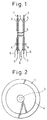
- Figure 1 and Fig. 2 show an example of a driving device for driving an acoustic vibration plate of a sound generating device.
- the driving device is comprised of a pair of disk-shaped metal piezoelectric vibration plates 1 and 2 arranged facing each other across a certain distance in the axial direction. The centers of these piezoelectric vibration plates 1 and 2 are connected to each other by a metal or plastic connecting rod 3.
- On the two sides of each of the piezoelectric vibration plates 1 and 2 are formed annular piezoelectric ceramic layers 4. Accordingly, in the example shown in Fig. 1 and Fig. 2, the piezoelectric vibration plates 1 and 2 are comprised of bimorphs.
- Figure 1 shows the directions of polarization of the piezoelectric ceramic layers 4 of the piezoelectric vibration plates 1 and 2 by the arrows K.
- the piezoelectric vibration plates 1 and 2 are connected by the connecting rod 3 so that the direction of polarization K of the piezoelectric ceramic layers 4 of one piezoelectric vibration plate 1 becomes reverse from the direction of polarization K of the piezoelectric ceramic layers 4 of the other piezoelectric vibration plate 2.
- the piezoelectric vibration plate 2 is for example grounded through a lead wire 5.
- An identical driving voltage is applied through the lead wires 6 to thin film electrodes formed on the surfaces of the piezoelectric ceramic layers 4.
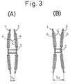
- the piezoelectric ceramic layers 4 formed on one side of the piezoelectric vibration plates 1 and 2 extend in the radial direction, while the piezoelectric ceramic layers 4 formed on the other side contract. As a result, the piezoelectric vibration plates 1 and 2 flex. In the example shown in Fig. 1, as mentioned above, the directions of polarization K of the piezoelectric ceramic layers 4 of the piezoelectric vibration plates 1 and 2 are reverse from each other.
- the piezoelectric vibration plates 1 and 2 flex in reverse directions from each other as shown in Fig. 3(A) and (B). That is, the state of the piezoelectric vibration plates 1 and 2 flexing outward to form a convex shape as shown in Fig. 3(A) and the state of the piezoelectric vibration plates 1 and 2 flexing inward to form a concave shape as shown in Fig. 3(B) are alternately repeated.
- the pair of piezoelectric vibration plates 1 and 2 shown in Fig. 1 shows the smallest unit of combination of piezoelectric vibration plates enabling increase of the output stroke.
- This smallest unit of combination is referred to as a "module”.
- the module obtained by connecting the centers of the pair of the piezoelectric vibration plates 1 and 2 as shown in Fig. 1 is referred to below as a "type I module”.
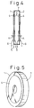
- Figure 4 and Fig. 5 show a module of a construction different from the module shown in Fig. 1. Note that in Fig. 4 and Fig. 5, constituent elements similar to those of Fig. 1 are shown by the same reference numerals.
- the outer peripheries of the pair of piezoelectric vibration plates 1 and 2 are affixed to a metal annular spacer 7 extending along the outer peripheries of the piezoelectric vibration plates 1 and 2. Accordingly, in the example shown in Fig. 4 and Fig. 5, the pair of piezoelectric vibration plates 1 and 2 are connected to each other through the annular spacer 7. In the example shown in Fig. 4 and Fig.
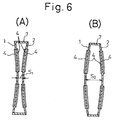
- the direction of polarization K of the piezoelectric ceramic layers 4 of one piezoelectric vibration plate 1 is reverse to that of the direction of polarization K of the piezoelectric ceramic layers 4 of the other piezoelectric vibration plate 2 and an identical drive voltage is applied through the lead wires 6 to the thin film electrodes of the piezoelectric ceramic layers 4. Accordingly, in this case too, when a positive voltage and negative voltage are alternately applied to the thin film electrodes of the piezoelectric ceramic layers 4, the piezoelectric vibration plates 1 and 2 flex alternately in reverse directions as shown by Fig. 6(A) and 6(B).
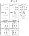
- the representative modules in the case of use of a pair of piezoelectric vibration plates 1 and 2 are the type I module and type II module explained above. These modules may be used as the basis for preparing driving devices comprised of various combinations of three or more piezoelectric vibration plates. Typical examples of these driving devices are shown in Fig. 7. Note that in Fig. 7, the driving devices shown in the column with two piezoelectric vibration plates are the type I module and type II module explained above.
- the driving devices comprised of combinations of three piezoelectric vibration plates are shown as type III and type IV.
- the driving device shown by type III is a combination of the type II module with a single piezoelectric vibration plate 8 and is formed by connecting the center of the piezoelectric vibration plate 2 constituting part of the type II module with the center of the single piezoelectric vibration plate 8 by a connecting rod 3.
- this driving device when a drive voltage is applied, the piezoelectric vibration plate 2 and the piezoelectric vibration plate 8 flex in reverse directions from each other. Therefore, this driving device gives an output stroke three times the output stroke when using a single piezoelectric vibration plate.
- the driving device shown by type IV is also a combination of a type II module and a single piezoelectric vibration plate 9 and is formed by connecting the center of the piezoelectric vibration plate 1 constituting part of the type II module and the center of the single piezoelectric vibration plate 9 by a connecting rod 3.
- this driving device when a drive voltage is applied, the piezoelectric vibration plate 1 and the piezoelectric vibration plate 9 flex in reverse directions from each other and therefore this driving device also gives an output stroke three times the output stroke when using a single piezoelectric vibration plate.
- the driving devices comprising combinations of four piezoelectric vibration plates are shown as type V and type VI.
- the driving device shown by type V is a combination of the type II module and two piezoelectric vibration plates 8 and 9.
- a type II module is inserted between the pair of piezoelectric vibration plates 1 and 2 of a type I module. That is, this driving device is formed by connecting the center of one piezoelectric vibration plate 1 constituting part of the type II module and the center of the piezoelectric vibration plate 9 by a connecting rod 3 and connecting the other piezoelectric vibration plate 2 constituting the type II module and the center of the piezoelectric vibration plate 8 by a connecting rod 3.
- the piezoelectric vibration plate 1 and the piezoelectric vibration plate 9 flex in opposite directions to each other and the piezoelectric vibration plate 2 and the piezoelectric vibration plate 8 flex in opposite directions to each other, so an output stroke four times the output stroke when using a single piezoelectric vibration plate can be obtained.
- the driving device shown by type VI is a combination of two type II modules and is formed by connecting the centers of the piezoelectric vibration plates 1 and 2 of the modules facing each other by a connecting rod 3. In this driving device too, it is possible to obtain a stroke four times the output stroke when using a single piezoelectric vibration plate.
- the driving devices comprising combinations of five piezoelectric vibration plates are shown as type VII and type VIII.
- the driving devices comprising combinations of six piezoelectric vibration plates are shown as type IX and type X.
- the configurations of the type VII, VIII, IX, and X driving devices are clear from Fig. 7, so no particular explanation will be made, but in each of the driving devices of the type VII, VIII, IX, and X, the mutually adjoining piezoelectric vibration plates 1, 2, 8, and 9 flex in mutually opposite directions when a drive voltage is applied.
- an output stroke five times the output stroke when using a single piezoelectric vibration plate is obtained, while in the type IX and X driving devices, an output stroke six times the output stroke when using a single piezoelectric vibration plate is obtained. Note that while not shown in Fig. 7, it is possible to form a driving device comprising seven or more piezoelectric vibration plates in a similar way.
- Figure 8 and Fig. 9 show the case of application of the present invention to a speaker and use of the type I module shown in Fig. 1 as a driving device for the speaker.
- reference numeral 10 shows a speaker frame and 11 an acoustic vibration plate.
- the outer periphery of the acoustic vibration plate 11 is bonded to the outer periphery of the speaker frame 10. Further, a packing 11a is bonded on the outer periphery of the acoustic vibration plate 11.
- the acoustic vibration plate 11 is formed from cone paper, but the acoustic vibration plate 11 may be formed from wood, plastic, or a thin metal sheet.
- the inner periphery of the acoustic vibration plate 11 is connected to the outer periphery of one of the piezoelectric vibration plates 1 of the driving device 12, while the outer periphery of the other piezoelectric vibration plate 1 of the driving device 12 is connected to the speaker frame 10.
- a piezoelectric vibration plate has a high natural frequency and the sound pressure level falls as this frequency falls.
- the drive stroke given by the driving device 12 to the acoustic vibration plate 11 becomes twice that when using a single acoustic vibration plate, so the amplitude of the acoustic vibration plate 11 becomes larger even in the low frequency region and therefore the bass sound pressure level can be made higher.
- the natural frequency of the driving device 12 becomes considerably lower than the natural frequency of the piezoelectric vibration plates and as a result the resonance point moves to the low frequency side. Accordingly, from this viewpoint as well, the amplitude of the acoustic vibration plate at the low frequency region can be made larger and therefore the bass sound pressure level can be raised much higher.
- Figure 10 shows another embodiment.
- an annular elastic member 13 comprised of rubber is attached to the outer periphery of the piezoelectric vibration plate 2. That is, as shown in Fig. 10, since the elastic member 13 has a relatively large mass, it is possible to further reduce the natural frequency of the driving device 13 and therefore to further raise even the bass sound pressure level. Further, if the natural frequency of the driving device 13 is reduced, the resonance point appears at the bass region, but the elastic member 13 functions to reduce the Q value at this resonance point and to reduce the Q value at the next higher resonance point appearing in the high frequency region.
- this elastic member 13 acts to suppress the movement of the peripheral portion of the piezoelectric vibration plate 2 in the forward-reverse direction due to its inertia. Accordingly, as shown in Fig. 10, even if the elastic member 13 is not supported by the speaker frame 10, the acoustic vibration plate 11 is made to oscillate when the piezoelectric vibration plates 1 and 2 engage in flexing motion. When the speed of flexing motion of the piezoelectric vibration plate 2 is slow, however, that is, in the low frequency region, the elastic member 13 moves as a whole in accordance with the movement of the peripheral portion of the piezoelectric vibration plate 2.
- the elastic member 13 when the speed of flexing motion of the piezoelectric vibration plate 2 is fast, that is, in the high frequency region, the elastic member 13 as a whole cannot follow the movement of the peripheral portion of the piezoelectric vibration plate 2 and therefore the movement of the outer periphery of the elastic member 13 lags behind the movement of the inner periphery of the elastic member 13. As a result, the elastic member 13 deforms. This deformation motion is repeated.
- This deformation of the elastic member 13 occurs due to the vibration energy and therefore the larger the amount of deformation of the elastic member 13, the greater the vibration energy consumed to cause the deformation of the elastic member 13. In other words, the larger the amount of deformation of the elastic member 13, the greater the vibration energy absorbed by the elastic member 13. However, as explained above, the amount of deformation of the elastic member 13 becomes greater the higher the frequency. Accordingly, as shown in Fig. 10, if the elastic member 13 is attached to the piezoelectric vibration plate 2, it becomes possible to attenuate the high frequency vibration by this elastic member 13. As a result, it is possible to relatively increase the amplitude of the low frequency region and therefore to raise the bass sound pressure level.
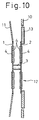
- FIG 11 shows still another embodiment.
- the outer periphery of the annular elastic member 13 is affixed to the speaker frame 10. If the outer periphery of the elastic member 13 is affixed to the speaker frame 10 in this way, the amount of deformation of the elastic member 13 at the time of occurrence of high frequency oscillation becomes further greater and therefore it becomes possible to further attenuate the high frequency oscillation and possible to further reduce the Q value. Also, if the outer periphery of the elastic member 13 is affixed to the speaker frame 10, it becomes possible to greatly suppress the amount of movement of the outer periphery of the piezoelectric vibration plate 2 in the forward-reverse direction at the time of occurrence of low frequency oscillation. As a result, it is possible to increase the amplitude of the acoustic vibration plate 11 at the low frequency region and therefore to increase the bass sound pressure level.
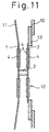
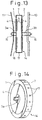
- Figure 12 to Fig. 14 show the case of use of the module of the type II shown in Fig. 4 as the driving device of a speaker.
- the driving device 14 comprised of a module of type II is arranged between the acoustic vibration plate 11 and the speaker frame 10.
- the center of one piezoelectric vibration plate 1 constituting the type II module is connected to the center of the acoustic vibration plate 11 through a metal or plastic connecting rod 3a by for example a nut 15, while the center of the other piezoelectric vibration plate 2 constituting the type II module is connected to the speaker frame 10 through a metal or plastic connecting rod 3b by for example the nut 16.
- the drive stroke given by the driving device 14 to the acoustic vibration plate 11 becomes double that when using a single piezoelectric vibration plate, so the amplitude of the acoustic vibration plate 11 becomes larger even in the low frequency region and therefore it is possible to raise the bass sound pressure level.
- the natural frequency of the driving device 14 becomes considerably lower than the natural frequency of the piezoelectric vibration plates and, as a result, the resonance point moves to the low frequency side. Accordingly, from this viewpoint as well, it is possible to increase the amplitude of the acoustic vibration plate 11 in the low frequency region and therefore the bass sound pressure level is raised much higher.
- a plurality of communicating holes 17 are formed in the annular spacer 7 and an air damper chamber 18 communicating through these communicating holes 17 to the outside air is formed between the pair of piezoelectric vibration plates.
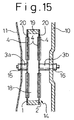
- FIG 15 shows still another embodiment.
- the annular spacer 19 connecting the peripheral portions of the piezoelectric vibration plates 1 and 2 together is formed from an elastic member such as rubber and a plurality of communicating holes 20 communicating the air damper chamber 18 with the outside air are formed in the peripheral portions of the piezoelectric vibration plates 1 and 2. Accordingly, in this embodiment too, it is possible to relatively raise the bass sound pressure level by the attenuation action of the air damper chamber 18 on the high frequency oscillation and possible to make the sound pressure level flat over a wide frequency region. Further, in this embodiment, the higher the frequency, the greater the frequency of deformation of the elastic member 19, so the higher the frequency, the greater the amount of absorption of oscillation by the elastic member 19. Accordingly, in this embodiment, it is possible to further cause the high frequency oscillation to attenuate.
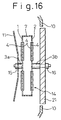
- Figure 16 shows still another embodiment.
- the center of the elastic plate 21 comprised of rubber is connected to the center of the piezoelectric vibration plate 2 through a connecting rod 3b by a nut 16.
- This elastic plate 21 acts in a similar way as the elastic member 13 shown in Fig. 10.
- the elastic plate 21 has a relatively large mass and therefore the elastic plate 21 acts to suppress the movement of the center of the piezoelectric vibration plate 2 in the forward-reverse direction by its inertia. Accordingly, as shown in Fig. 16, even if the elastic plate 21 is not supported by the speaker frame 10, the acoustic vibration plate 11 is made to vibrate when the piezoelectric vibration plates 1 and 2 engage in flexing motion. On the other hand, when the speed of flexing motion of the piezoelectric vibration plates 1 and 2 is slow, that is, in the low frequency region, the elastic body 21 moves as a whole in accordance with the movement of the center of the piezoelectric vibration plate 2.
- the elastic body 21 As opposed to this, when the speed of flexing motion of the piezoelectric vibration plates 1 and 2 is fast, that is, in the high frequency region, the elastic body 21 as a whole cannot follow the movement of the center of the piezoelectric vibration plate 2 and therefore the movement of the outer periphery of the elastic body 21 lags behind the movement of the center of the elastic body 21. As a result, the elastic body 21 deforms and this deformation motion is repeated.
- the amount of deformation of the elastic plate 21 shown in Fig. 16 becomes larger the higher the frequency. Accordingly, as shown in Fig. 16, if the elastic plate 21 is attached to the piezoelectric vibration plate 2, it is possible to cause the high frequency oscillation to attenuate by the elastic plate 21. As a result, it becomes possible to relatively increase the amplitude at the low frequency region and therefore to raise the bass sound pressure level.
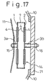
- Figure 17 shows still another embodiment.
- the outer periphery of the elastic plate 21 is affixed to the speaker frame 10. If the outer periphery of the elastic plate 21 is affixed to the speaker frame 10 in this way, the amount of deformation of the elastic plate 21 at the time of occurrence of high frequency oscillation becomes larger and therefore it is possible to further cause the high frequency oscillation to attenuate and further cause the Q value to fall. Also, if the outer periphery of the elastic plate 21 is affixed to the speaker frame 10, the amount of movement of the center of the piezoelectric vibration plate 2 in the forward-reverse direction at the time of occurrence of low frequency oscillation on can be suppressed to a large extent. As a result, it is possible to increase the amplitude of the acoustic vibration plate 11 in the low frequency region and therefore to increase the bass sound pressure level.
- Figure 18 shows the case of use of the driving device of the type VI shown in Fig. 7 as the driving device of a speaker. That is, in the embodiment shown in Fig. 18, the driving device 22 has a construction of two modules of type II shown in Fig. 4 connected in series. The centers of the two piezoelectric vibration plates positioned at the center among the four piezoelectric vibration plates 1 and 2 are connected to each other by a connecting rod 3c. In this embodiment, as explained above, it is possible to obtain an output stroke four times that of the case of use of a single piezoelectric vibration plate as mentioned above.
- Figure 19 shows a modification of the driving device 22 shown in Fig. 18.
- the centers of the two piezoelectric vibration plates 1 and 2 positioned at the center among the four piezoelectric vibration plates 1 and 2 are connected by a hollow sleeve 23. Accordingly, in this embodiment, the air damper chambers 18 formed in the modules are communicated with each other through the hollow sleeve 23.
- Figure 20 shows the case of application of a construction in which use is made of a driving device of the type III shown in Fig. 7 as the driving device of the speaker and use is made of the annular elastic member 13 shown in Fig. 11 to cause attenuation of the high frequency oscillation of the driving device 24. That is, in the driving device 24, the center of the piezoelectric vibration plate 2 constituting part of the type II module and the center of the single piezoelectric vibration plate 8 are connected to each other through a connecting rod 3b. The peripheral portion of the single piezoelectric vibration plate 8 is connected to the speaker frame 10 through an annular elastic member 13 comprised of a rubber.
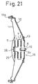
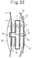
- Figure 21 and Fig. 22 show the case of application of a construction in which use is made of a driving device of the type V shown in Fig. 7 as the driving device of the speaker and use is made of the annular elastic member 13 shown in Fig. 11 to cause attenuation of the high frequency vibration of the driving device 25. That is, in the driving device 25, the center of the piezoelectric vibration plate 2 constituting part of the type II module and the center of the single piezoelectric vibration plate 8 are connected to each other through a connecting rod 3b by a bolt 26 and nut 16. The peripheral portion of the single piezoelectric vibration plate 8 is connected to the speaker frame 10 through an annular elastic member 13 comprised of a rubber.
- the center of the piezoelectric vibration plate 1 constituting part of the type II module and the center of the single piezoelectric vibration plate 9 are connected to each other through the hollow sleeve 27.
- the outer periphery of the single piezoelectric vibration plate 9 is connected to the inner periphery of the acoustic vibration plate 11.
- the front end of the hollow sleeve 27 opens to the outside.
- the opening of the hollow sleeve 27 is closed off by a plug 28 made of a plastic material, for example.
- the plug 28 is not inserted before assembling the driving device 25.
- the plug 28 is inserted into the opening of the hollow sleeve 27 after bolting the piezoelectric vibration plates 2 and 8. This forms an air damper chamber 18 between the piezoelectric vibration plates 1 and 2.
- a diaphragm 29 is attached to cover the single piezoelectric vibration plate 9.
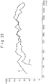
- Figure 23 shows the results of an experiment investigating the relationship between the frequency f and the sound pressure level P.
- A shows a speaker of the construction shown in Fig. 12, while B shows a speaker of the construction shown in Fig. 21.
- Fig. 23 shows the case of application of a drive voltage giving a substantially equal sound pressure level P at a frequency f of 1000 Hz to the driving devices 14 and 25. From Fig. 23, it is learned that the speaker of the construction shown in Fig. 21 has a flat sound pressure level P across a wide frequency region.
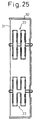
- Figure 24 and Fig. 25 show still another embodiment.
- reference numeral 30 shows a speaker frame and 31 shows an acoustic vibration plate.
- a plurality of driving devices 22 of the type VI in Fig. 7 are arranged in parallel between the speaker frame 30 and the acoustic vibration plate 31. Accordingly, in this embodiment, the acoustic vibration plate 31 is simultaneously driven by a plurality of driving devices 22. Note that in this case, it is possible to use any of the types of driving devices shown in Fig. 7.
- the speaker using the piezoelectric vibration plates of the present invention not only has the advantage of being much lighter in weight compared with the conventional dynamic speakers, but also has the advantage of not requiring the use of permanent magnets as in dynamic speakers and therefore not requiring anti-magnetic devices.
- the present invention was explained heretofore with reference to the case of application to a speaker, the present invention may be applied to all sound generating devices for producing sound, such as telephones or buzzers. Further, needless to say, unimorphs may be used as the piezoelectric vibration plates.
Abstract
Description
- The present invention relates to a sound generating device.
- As piezoelectric vibration plates, there are known unimorphs comprised of a disk-shaped thin metal plate with a piezoelectric ceramic layer formed on just one side and bimorphs comprised of a disk-shaped thin metal plate with piezoelectric ceramic layers formed on both sides. These unimorph and bimorph type piezoelectric vibration plates perform flexing oscillation wherein the centers of the piezoelectric vibration plates alternately flex in opposite directions when the voltage applied to the piezoelectric ceramic layers are changed. Known in the art is a speaker which uses such a flexing oscillation of a piezoelectric vibration plate to generate sound. In such a conventional speaker, the peripheral portion of the piezoelectric vibration plate was usually supported by the frame of the speaker, the center of the piezoelectric vibration plate was connected to an acoustic vibration plate, and the acoustic vibration plate was made to oscillate by the piezoelectric vibration plate so as to produce sound from the acoustic vibration plate (for example, see Japanese Unexamined Patent Publication (Kokai) No. 60-182300).
- This piezoelectric vibration plate, however, has a high natural frequency and a high Q value at the resonance point and has the property of a reduction in the sound pressure level along with a fall in the frequency. Accordingly, there is the problem that when, like in the past, the oscillation of the piezoelectric vibration plate is merely directly transmitted to the acoustic vibration plate as it is, the sound becomes distorted and the bass sound pressure level is insufficient at the resonance point.
- The object of the present invention is to provide a sound generating device which is able to give a sufficiently high sound pressure level even in the bass region.
- According to the present invention, there is provided a sound generating device provided with a driving device having a plurality of piezoelectric vibration plates which are arranged spaced from each other in an axial direction, wherein either of the peripheral portions or centers of adjacent piezoelectric vibration plates are connected to each other and adjacent piezoelectric vibration plates are made to flex in opposite directions from each other, the piezoelectric vibration plate positioned at one end of said plurality of piezoelectric vibration plates being connected to an acoustic vibration plate.
-
- Figure 1 is a cross-sectional side view of a type I module, Fig. 2 is a front view of the module shown in Fig. 1, Fig. 3 is a view for explaining the operation of the module shown in Fig. 1, Fig. 4 is a cross-sectional side view of a type II module, Fig. 5 is perspective view of the module shown in Fig. 4, Fig. 6 is a view for explaining the operation of the module shown in Fig. 4, Fig. 7 is view showing various driving devices, Fig. 8 is a cross-sectional side view of a speaker using the type I module shown in Fig. 1, Fig. 9 is a partially enlarged cross-sectional side view of Fig. 8, Fig. 10 is a cross-sectional side view of part of a speaker showing another embodiment, Fig. 11 is a cross-sectional side view of part of a speaker showing still another embodiment, Fig. 12 is a cross-sectional side view of a speaker using the type II speaker shown in Fig. 4, Fig. 13 is a partially enlarged cross-sectional side view of Fig. 12, Fig. 14 is a perspective view of the type II module, Fig. 15 is a cross-sectional side view of part of a speaker showing another embodiment, Fig. 16 is a cross-sectional side view of part of a speaker showing still another embodiment, Fig. 17 is a cross-sectional side view of part of a speaker showing still another embodiment, Fig. 18 is a cross-sectional side view of part of a speaker showing still another embodiment, Fig. 19 is a cross-sectional side view of part of a speaker showing a modification of Fig. 18, Fig. 20 is a cross-sectional side view of part of a speaker showing still another embodiment, Fig. 21 is a cross-sectional side view of part of a speaker showing still another embodiment, Fig. 22 is a partially enlarged cross-sectional side view of Fig. 21, Fig. 23 is a view showing the relationship of the frequency f and the sound pressure level P, Fig. 24 is a front view of a speaker showing another embodiment, and Fig. 25 is a cross-sectional view seen along line XXV-XXV of Fig. 24.
-
- Figure 1 and Fig. 2 show an example of a driving device for driving an acoustic vibration plate of a sound generating device. Referring to Fig. 1 and Fig. 2, the driving device is comprised of a pair of disk-shaped metal piezoelectric vibration plates 1 and 2 arranged facing each other across a certain distance in the axial direction. The centers of these piezoelectric vibration plates 1 and 2 are connected to each other by a metal or plastic connecting rod 3. On the two sides of each of the piezoelectric vibration plates 1 and 2 are formed annular piezoelectric ceramic layers 4. Accordingly, in the example shown in Fig. 1 and Fig. 2, the piezoelectric vibration plates 1 and 2 are comprised of bimorphs.
- Figure 1 shows the directions of polarization of the piezoelectric ceramic layers 4 of the piezoelectric vibration plates 1 and 2 by the arrows K. As shown in Fig. 1, in the example shown in Fig. 1, the piezoelectric vibration plates 1 and 2 are connected by the connecting rod 3 so that the direction of polarization K of the piezoelectric ceramic layers 4 of one piezoelectric vibration plate 1 becomes reverse from the direction of polarization K of the piezoelectric ceramic layers 4 of the other piezoelectric vibration plate 2. The piezoelectric vibration plate 2 is for example grounded through a lead wire 5. An identical driving voltage is applied through the lead wires 6 to thin film electrodes formed on the surfaces of the piezoelectric ceramic layers 4.
- When a voltage is applied to the thin film electrodes of the piezoelectric ceramic layers 4 of the piezoelectric vibration plates 1 and 2, the piezoelectric ceramic layers 4 formed on one side of the piezoelectric vibration plates 1 and 2 extend in the radial direction, while the piezoelectric ceramic layers 4 formed on the other side contract. As a result, the piezoelectric vibration plates 1 and 2 flex. In the example shown in Fig. 1, as mentioned above, the directions of polarization K of the piezoelectric ceramic layers 4 of the piezoelectric vibration plates 1 and 2 are reverse from each other. In this case, when a positive voltage and negative voltage are alternately applied through the lead wires 6 to the thin film electrodes of the piezoelectric ceramic layers 4, the piezoelectric vibration plates 1 and 2 flex in reverse directions from each other as shown in Fig. 3(A) and (B). That is, the state of the piezoelectric vibration plates 1 and 2 flexing outward to form a convex shape as shown in Fig. 3(A) and the state of the piezoelectric vibration plates 1 and 2 flexing inward to form a concave shape as shown in Fig. 3(B) are alternately repeated.
- In this case, if the distance between the peripheral portions of the piezoelectric vibration plates 1 and 2 in the state shown in Fig. 3(A) is made S1 and the distance between the peripheral portions of the piezoelectric vibration plates 1 and 2 in the state shown in Fig. 3(B) is made S2, then amount of displacement ΔS of the peripheral portions of the piezoelectric vibration plates 1 and 2 becomes
- In this way, it is possible to increase the output stroke by use of a pair of piezoelectric vibration plates 1 and 2. The pair of piezoelectric vibration plates 1 and 2 shown in Fig. 1 in this case shows the smallest unit of combination of piezoelectric vibration plates enabling increase of the output stroke. This smallest unit of combination is referred to as a "module". Note that the module obtained by connecting the centers of the pair of the piezoelectric vibration plates 1 and 2 as shown in Fig. 1 is referred to below as a "type I module".
- Figure 4 and Fig. 5 show a module of a construction different from the module shown in Fig. 1. Note that in Fig. 4 and Fig. 5, constituent elements similar to those of Fig. 1 are shown by the same reference numerals.
- Referring to Fig. 4 and Fig. 5, the outer peripheries of the pair of piezoelectric vibration plates 1 and 2 are affixed to a metal annular spacer 7 extending along the outer peripheries of the piezoelectric vibration plates 1 and 2. Accordingly, in the example shown in Fig. 4 and Fig. 5, the pair of piezoelectric vibration plates 1 and 2 are connected to each other through the annular spacer 7. In the example shown in Fig. 4 and Fig. 5 as well, the direction of polarization K of the piezoelectric ceramic layers 4 of one piezoelectric vibration plate 1 is reverse to that of the direction of polarization K of the piezoelectric ceramic layers 4 of the other piezoelectric vibration plate 2 and an identical drive voltage is applied through the lead wires 6 to the thin film electrodes of the piezoelectric ceramic layers 4. Accordingly, in this case too, when a positive voltage and negative voltage are alternately applied to the thin film electrodes of the piezoelectric ceramic layers 4, the piezoelectric vibration plates 1 and 2 flex alternately in reverse directions as shown by Fig. 6(A) and 6(B).
- In this case, if the distance between the centers of the piezoelectric vibration plates 1 and 2 in the state shown in Fig. 6(A) is made S1 and the distance between the centers of the piezoelectric vibration plates 1 and 2 in the state shown in Fig. 6(B) is made S2, then the amount of displacement ΔS of the centers of the piezoelectric vibration plates 1 and 2 becomes
- The representative modules in the case of use of a pair of piezoelectric vibration plates 1 and 2 are the type I module and type II module explained above. These modules may be used as the basis for preparing driving devices comprised of various combinations of three or more piezoelectric vibration plates. Typical examples of these driving devices are shown in Fig. 7. Note that in Fig. 7, the driving devices shown in the column with two piezoelectric vibration plates are the type I module and type II module explained above.
- Referring to Fig. 7, the driving devices comprised of combinations of three piezoelectric vibration plates are shown as type III and type IV. The driving device shown by type III is a combination of the type II module with a single piezoelectric vibration plate 8 and is formed by connecting the center of the piezoelectric vibration plate 2 constituting part of the type II module with the center of the single piezoelectric vibration plate 8 by a connecting rod 3. In this driving device, when a drive voltage is applied, the piezoelectric vibration plate 2 and the piezoelectric vibration plate 8 flex in reverse directions from each other. Therefore, this driving device gives an output stroke three times the output stroke when using a single piezoelectric vibration plate.
- The driving device shown by type IV is also a combination of a type II module and a single piezoelectric vibration plate 9 and is formed by connecting the center of the piezoelectric vibration plate 1 constituting part of the type II module and the center of the single piezoelectric vibration plate 9 by a connecting rod 3. In this driving device as well, when a drive voltage is applied, the piezoelectric vibration plate 1 and the piezoelectric vibration plate 9 flex in reverse directions from each other and therefore this driving device also gives an output stroke three times the output stroke when using a single piezoelectric vibration plate.
- On the other hand, as shown in Fig. 7, the driving devices comprising combinations of four piezoelectric vibration plates are shown as type V and type VI. The driving device shown by type V is a combination of the type II module and two piezoelectric vibration plates 8 and 9. Seen in another way, a type II module is inserted between the pair of piezoelectric vibration plates 1 and 2 of a type I module. That is, this driving device is formed by connecting the center of one piezoelectric vibration plate 1 constituting part of the type II module and the center of the piezoelectric vibration plate 9 by a connecting rod 3 and connecting the other piezoelectric vibration plate 2 constituting the type II module and the center of the piezoelectric vibration plate 8 by a connecting rod 3. In this driving device, when a drive voltage is applied, the piezoelectric vibration plate 1 and the piezoelectric vibration plate 9 flex in opposite directions to each other and the piezoelectric vibration plate 2 and the piezoelectric vibration plate 8 flex in opposite directions to each other, so an output stroke four times the output stroke when using a single piezoelectric vibration plate can be obtained.
- On the other hand, the driving device shown by type VI is a combination of two type II modules and is formed by connecting the centers of the piezoelectric vibration plates 1 and 2 of the modules facing each other by a connecting rod 3. In this driving device too, it is possible to obtain a stroke four times the output stroke when using a single piezoelectric vibration plate.
- Further, as shown in Fig. 7, the driving devices comprising combinations of five piezoelectric vibration plates are shown as type VII and type VIII. The driving devices comprising combinations of six piezoelectric vibration plates are shown as type IX and type X. The configurations of the type VII, VIII, IX, and X driving devices are clear from Fig. 7, so no particular explanation will be made, but in each of the driving devices of the type VII, VIII, IX, and X, the mutually adjoining piezoelectric vibration plates 1, 2, 8, and 9 flex in mutually opposite directions when a drive voltage is applied. Accordingly, in the type VII and VIII driving devices, an output stroke five times the output stroke when using a single piezoelectric vibration plate is obtained, while in the type IX and X driving devices, an output stroke six times the output stroke when using a single piezoelectric vibration plate is obtained. Note that while not shown in Fig. 7, it is possible to form a driving device comprising seven or more piezoelectric vibration plates in a similar way.
- Next, an explanation will be made of representative examples of the sound generating device using the driving devices shown in Fig. 7 to drive the acoustic vibration plate.
- Figure 8 and Fig. 9 show the case of application of the present invention to a speaker and use of the type I module shown in Fig. 1 as a driving device for the speaker.
- Referring to Fig. 8 and Fig. 9, reference numeral 10 shows a speaker frame and 11 an acoustic vibration plate. The outer periphery of the acoustic vibration plate 11 is bonded to the outer periphery of the speaker frame 10. Further, a packing 11a is bonded on the outer periphery of the acoustic vibration plate 11. In the embodiment shown in Fig. 8 and Fig. 9, the acoustic vibration plate 11 is formed from cone paper, but the acoustic vibration plate 11 may be formed from wood, plastic, or a thin metal sheet. The inner periphery of the acoustic vibration plate 11 is connected to the outer periphery of one of the piezoelectric vibration plates 1 of the driving device 12, while the outer periphery of the other piezoelectric vibration plate 1 of the driving device 12 is connected to the speaker frame 10.
- As explained at the start, a piezoelectric vibration plate has a high natural frequency and the sound pressure level falls as this frequency falls. In the embodiment shown in Fig. 8 and Fig. 9, however, the drive stroke given by the driving device 12 to the acoustic vibration plate 11 becomes twice that when using a single acoustic vibration plate, so the amplitude of the acoustic vibration plate 11 becomes larger even in the low frequency region and therefore the bass sound pressure level can be made higher.
- Further, if the pair of piezoelectric vibration plates 1 and 2 are connected with each other by a connecting rod 3, the natural frequency of the driving device 12 becomes considerably lower than the natural frequency of the piezoelectric vibration plates and as a result the resonance point moves to the low frequency side. Accordingly, from this viewpoint as well, the amplitude of the acoustic vibration plate at the low frequency region can be made larger and therefore the bass sound pressure level can be raised much higher.
- Figure 10 shows another embodiment. As shown in Fig. 10, in this embodiment, to lower the natural frequency of the driving device 13 and further to make the sound pressure level flat over a wide frequency region, an annular elastic member 13 comprised of rubber is attached to the outer periphery of the piezoelectric vibration plate 2. That is, as shown in Fig. 10, since the elastic member 13 has a relatively large mass, it is possible to further reduce the natural frequency of the driving device 13 and therefore to further raise even the bass sound pressure level. Further, if the natural frequency of the driving device 13 is reduced, the resonance point appears at the bass region, but the elastic member 13 functions to reduce the Q value at this resonance point and to reduce the Q value at the next higher resonance point appearing in the high frequency region.
- That is, since the elastic member 13 has a relatively large mass as explained above, this elastic member 13 acts to suppress the movement of the peripheral portion of the piezoelectric vibration plate 2 in the forward-reverse direction due to its inertia. Accordingly, as shown in Fig. 10, even if the elastic member 13 is not supported by the speaker frame 10, the acoustic vibration plate 11 is made to oscillate when the piezoelectric vibration plates 1 and 2 engage in flexing motion. When the speed of flexing motion of the piezoelectric vibration plate 2 is slow, however, that is, in the low frequency region, the elastic member 13 moves as a whole in accordance with the movement of the peripheral portion of the piezoelectric vibration plate 2. As opposed to this, when the speed of flexing motion of the piezoelectric vibration plate 2 is fast, that is, in the high frequency region, the elastic member 13 as a whole cannot follow the movement of the peripheral portion of the piezoelectric vibration plate 2 and therefore the movement of the outer periphery of the elastic member 13 lags behind the movement of the inner periphery of the elastic member 13. As a result, the elastic member 13 deforms. This deformation motion is repeated.
- This deformation of the elastic member 13 occurs due to the vibration energy and therefore the larger the amount of deformation of the elastic member 13, the greater the vibration energy consumed to cause the deformation of the elastic member 13. In other words, the larger the amount of deformation of the elastic member 13, the greater the vibration energy absorbed by the elastic member 13. However, as explained above, the amount of deformation of the elastic member 13 becomes greater the higher the frequency. Accordingly, as shown in Fig. 10, if the elastic member 13 is attached to the piezoelectric vibration plate 2, it becomes possible to attenuate the high frequency vibration by this elastic member 13. As a result, it is possible to relatively increase the amplitude of the low frequency region and therefore to raise the bass sound pressure level.
- On the other hand, at the resonance point, not only does the amplitude become larger, but also the speed of flexing motion of the piezoelectric vibration plate 2 becomes faster and therefore the oscillation at the resonance point is attenuated by the elastic member 13. Accordingly, if the elastic member 13 is attached to the piezoelectric vibration plate 2, the Q value becomes smaller and therefore the sound pressure level can be made flat over a wide frequency region.
- Figure 11 shows still another embodiment. In this embodiment, the outer periphery of the annular elastic member 13 is affixed to the speaker frame 10. If the outer periphery of the elastic member 13 is affixed to the speaker frame 10 in this way, the amount of deformation of the elastic member 13 at the time of occurrence of high frequency oscillation becomes further greater and therefore it becomes possible to further attenuate the high frequency oscillation and possible to further reduce the Q value. Also, if the outer periphery of the elastic member 13 is affixed to the speaker frame 10, it becomes possible to greatly suppress the amount of movement of the outer periphery of the piezoelectric vibration plate 2 in the forward-reverse direction at the time of occurrence of low frequency oscillation. As a result, it is possible to increase the amplitude of the acoustic vibration plate 11 at the low frequency region and therefore to increase the bass sound pressure level.
- Figure 12 to Fig. 14 show the case of use of the module of the type II shown in Fig. 4 as the driving device of a speaker.
- Referring to Fig. 12 and Fig. 13, the driving device 14 comprised of a module of type II is arranged between the acoustic vibration plate 11 and the speaker frame 10. The center of one piezoelectric vibration plate 1 constituting the type II module is connected to the center of the acoustic vibration plate 11 through a metal or plastic connecting rod 3a by for example a nut 15, while the center of the other piezoelectric vibration plate 2 constituting the type II module is connected to the speaker frame 10 through a metal or plastic connecting rod 3b by for example the nut 16. In this embodiment too, the drive stroke given by the driving device 14 to the acoustic vibration plate 11 becomes double that when using a single piezoelectric vibration plate, so the amplitude of the acoustic vibration plate 11 becomes larger even in the low frequency region and therefore it is possible to raise the bass sound pressure level.
- Further, when the pair of piezoelectric vibration plates 1 and 2 are connected to each other by an annular spacer 7 as in this embodiment, the natural frequency of the driving device 14 becomes considerably lower than the natural frequency of the piezoelectric vibration plates and, as a result, the resonance point moves to the low frequency side. Accordingly, from this viewpoint as well, it is possible to increase the amplitude of the acoustic vibration plate 11 in the low frequency region and therefore the bass sound pressure level is raised much higher. Further, in this embodiment, to make the natural frequency of the driving device 13 lower and to make the sound pressure level flat over a wide frequency region, a plurality of communicating holes 17 are formed in the annular spacer 7 and an air damper chamber 18 communicating through these communicating holes 17 to the outside air is formed between the pair of piezoelectric vibration plates.
- If the air damper chamber 18 increases in volume due to the flexing motion of the piezoelectric vibration plates 1 and 2, outside air flows through the communicating holes 17 into the air damper chamber 18, while if the air damper chamber 18 decreases in volume, air in the air damper chamber 18 flows out to the outside air through the communicating holes 17. In this case, time is required for the inflowing and outflowing action of the air through the communicating holes 17, so the faster the speed of flexing motion of the piezoelectric vibration plates 1 and 2, that is, the higher the frequency of vibration, the harder it becomes for the piezoelectric vibration plates 1 and 2 to flex. That is, if the piezoelectric vibration plates 1 and 2 attempt to flex outward to give a convex shape as shown in Fig. 6(B), the pressure inside the air damper chamber 18 falls, so the flexing motion of the piezoelectric vibration plates 1 and 2 is suppressed, while when the piezoelectric vibration plates 1 and 2 attempt to flex inward to give a concave shape as shown in Fig. 6(A), the pressure inside the air damper chamber 18 rises, so the flexing motion of the piezoelectric vibration plates 1 and 2 is suppressed. In this way, due to the damper action of the air damper chamber 18, the faster the speed of flexing motion of the piezoelectric vibration plates 1 and 2, the more the flexing motion of the piezoelectric vibration plates 1 and 2 is suppressed. In other words, the faster the speed of flexing motion of the piezoelectric vibration plates 1 and 2, that is, the higher the frequency of oscillation, the more the oscillation of the piezoelectric vibration plates 1 and 2 is suppressed. Accordingly, by providing such an air damper chamber 18, it is possible to relatively increase the bass sound pressure level and further reduce the Q value at the resonance point, so it is possible to make the sound pressure level flat over a wide frequency region.
- Figure 15 shows still another embodiment. In this embodiment, the annular spacer 19 connecting the peripheral portions of the piezoelectric vibration plates 1 and 2 together is formed from an elastic member such as rubber and a plurality of communicating holes 20 communicating the air damper chamber 18 with the outside air are formed in the peripheral portions of the piezoelectric vibration plates 1 and 2. Accordingly, in this embodiment too, it is possible to relatively raise the bass sound pressure level by the attenuation action of the air damper chamber 18 on the high frequency oscillation and possible to make the sound pressure level flat over a wide frequency region. Further, in this embodiment, the higher the frequency, the greater the frequency of deformation of the elastic member 19, so the higher the frequency, the greater the amount of absorption of oscillation by the elastic member 19. Accordingly, in this embodiment, it is possible to further cause the high frequency oscillation to attenuate.
- Figure 16 shows still another embodiment. Referring to Fig. 16, in this embodiment, the center of the elastic plate 21 comprised of rubber is connected to the center of the piezoelectric vibration plate 2 through a connecting rod 3b by a nut 16. This elastic plate 21 acts in a similar way as the elastic member 13 shown in Fig. 10.
- That is, the elastic plate 21 has a relatively large mass and therefore the elastic plate 21 acts to suppress the movement of the center of the piezoelectric vibration plate 2 in the forward-reverse direction by its inertia. Accordingly, as shown in Fig. 16, even if the elastic plate 21 is not supported by the speaker frame 10, the acoustic vibration plate 11 is made to vibrate when the piezoelectric vibration plates 1 and 2 engage in flexing motion. On the other hand, when the speed of flexing motion of the piezoelectric vibration plates 1 and 2 is slow, that is, in the low frequency region, the elastic body 21 moves as a whole in accordance with the movement of the center of the piezoelectric vibration plate 2. As opposed to this, when the speed of flexing motion of the piezoelectric vibration plates 1 and 2 is fast, that is, in the high frequency region, the elastic body 21 as a whole cannot follow the movement of the center of the piezoelectric vibration plate 2 and therefore the movement of the outer periphery of the elastic body 21 lags behind the movement of the center of the elastic body 21. As a result, the elastic body 21 deforms and this deformation motion is repeated.
- In this case, however, the larger the amount of deformation of the elastic plate 21, the larger the vibration energy absorbed by the elastic plate 21. The amount of deformation of the elastic plate 21 shown in Fig. 16 becomes larger the higher the frequency. Accordingly, as shown in Fig. 16, if the elastic plate 21 is attached to the piezoelectric vibration plate 2, it is possible to cause the high frequency oscillation to attenuate by the elastic plate 21. As a result, it becomes possible to relatively increase the amplitude at the low frequency region and therefore to raise the bass sound pressure level.
- Further, as explained above, not only does the amplitude become larger at the resonance point, but also the speed of the flexing motion of the piezoelectric vibration plates 1 and 2 increases. Therefore, the oscillation at the resonance point is attenuated by the elastic plate 21. Accordingly, if the elastic plate 21 is attached to the piezoelectric vibration plate 2, the Q value becomes smaller and therefore it is possible to make the sound pressure level flat over a wide frequency region.
- Figure 17 shows still another embodiment. In this embodiment, the outer periphery of the elastic plate 21 is affixed to the speaker frame 10. If the outer periphery of the elastic plate 21 is affixed to the speaker frame 10 in this way, the amount of deformation of the elastic plate 21 at the time of occurrence of high frequency oscillation becomes larger and therefore it is possible to further cause the high frequency oscillation to attenuate and further cause the Q value to fall. Also, if the outer periphery of the elastic plate 21 is affixed to the speaker frame 10, the amount of movement of the center of the piezoelectric vibration plate 2 in the forward-reverse direction at the time of occurrence of low frequency oscillation on can be suppressed to a large extent. As a result, it is possible to increase the amplitude of the acoustic vibration plate 11 in the low frequency region and therefore to increase the bass sound pressure level.
- Up to now, the present invention has been explained in relation to the case of application to a driving device 12 comprised of type I module and a driving device 14 comprised of the type II module, but the constructions of the embodiments explained up to here may be applied to the various driving devices of the constructions shown as type III to type X in Fig. 7. Below, an explanation will be made of typical examples of application of the constructions of the embodiments explained above to driving devices of the constructions shown as type III to type X.
- Figure 18 shows the case of use of the driving device of the type VI shown in Fig. 7 as the driving device of a speaker. That is, in the embodiment shown in Fig. 18, the driving device 22 has a construction of two modules of type II shown in Fig. 4 connected in series. The centers of the two piezoelectric vibration plates positioned at the center among the four piezoelectric vibration plates 1 and 2 are connected to each other by a connecting rod 3c. In this embodiment, as explained above, it is possible to obtain an output stroke four times that of the case of use of a single piezoelectric vibration plate as mentioned above.
- Figure 19 shows a modification of the driving device 22 shown in Fig. 18. In this modification, the centers of the two piezoelectric vibration plates 1 and 2 positioned at the center among the four piezoelectric vibration plates 1 and 2 are connected by a hollow sleeve 23. Accordingly, in this embodiment, the air damper chambers 18 formed in the modules are communicated with each other through the hollow sleeve 23.
- Figure 20 shows the case of application of a construction in which use is made of a driving device of the type III shown in Fig. 7 as the driving device of the speaker and use is made of the annular elastic member 13 shown in Fig. 11 to cause attenuation of the high frequency oscillation of the driving device 24. That is, in the driving device 24, the center of the piezoelectric vibration plate 2 constituting part of the type II module and the center of the single piezoelectric vibration plate 8 are connected to each other through a connecting rod 3b. The peripheral portion of the single piezoelectric vibration plate 8 is connected to the speaker frame 10 through an annular elastic member 13 comprised of a rubber.
- Figure 21 and Fig. 22 show the case of application of a construction in which use is made of a driving device of the type V shown in Fig. 7 as the driving device of the speaker and use is made of the annular elastic member 13 shown in Fig. 11 to cause attenuation of the high frequency vibration of the driving device 25. That is, in the driving device 25, the center of the piezoelectric vibration plate 2 constituting part of the type II module and the center of the single piezoelectric vibration plate 8 are connected to each other through a connecting rod 3b by a bolt 26 and nut 16. The peripheral portion of the single piezoelectric vibration plate 8 is connected to the speaker frame 10 through an annular elastic member 13 comprised of a rubber. Further, in this driving device 25, the center of the piezoelectric vibration plate 1 constituting part of the type II module and the center of the single piezoelectric vibration plate 9 are connected to each other through the hollow sleeve 27. The outer periphery of the single piezoelectric vibration plate 9 is connected to the inner periphery of the acoustic vibration plate 11.
- Further, in this driving device 25, the front end of the hollow sleeve 27 opens to the outside. The opening of the hollow sleeve 27 is closed off by a plug 28 made of a plastic material, for example. The plug 28 is not inserted before assembling the driving device 25. When the driving device 25 is being assembled, the plug 28 is inserted into the opening of the hollow sleeve 27 after bolting the piezoelectric vibration plates 2 and 8. This forms an air damper chamber 18 between the piezoelectric vibration plates 1 and 2. In this driving device 25, further, a diaphragm 29 is attached to cover the single piezoelectric vibration plate 9.
- With this driving device 25, an output stroke four times the case of use of a single piezoelectric vibration plate is obtained. Further, with this driving device 25, the resonance frequency of the driving device 25 becomes much smaller and, further, the high frequency oscillation is attenuated to a large degree by the high frequency attenuation action of the air damper chamber 18 and the high frequency attenuation action of the elastic member 13, so the Q value is made much lower. As a result, it is possible to maintain a high sound pressure level overall and to obtain a flat sound pressure level over a wide frequency region.
- Figure 23 shows the results of an experiment investigating the relationship between the frequency f and the sound pressure level P. In Fig. 23, A shows a speaker of the construction shown in Fig. 12, while B shows a speaker of the construction shown in Fig. 21. Note that Fig. 23 shows the case of application of a drive voltage giving a substantially equal sound pressure level P at a frequency f of 1000 Hz to the driving devices 14 and 25. From Fig. 23, it is learned that the speaker of the construction shown in Fig. 21 has a flat sound pressure level P across a wide frequency region.
- Figure 24 and Fig. 25 show still another embodiment. Referring to Fig. 24 and Fig. 25, reference numeral 30 shows a speaker frame and 31 shows an acoustic vibration plate. In this embodiment, a plurality of driving devices 22 of the type VI in Fig. 7 are arranged in parallel between the speaker frame 30 and the acoustic vibration plate 31. Accordingly, in this embodiment, the acoustic vibration plate 31 is simultaneously driven by a plurality of driving devices 22. Note that in this case, it is possible to use any of the types of driving devices shown in Fig. 7.
- The speaker using the piezoelectric vibration plates of the present invention not only has the advantage of being much lighter in weight compared with the conventional dynamic speakers, but also has the advantage of not requiring the use of permanent magnets as in dynamic speakers and therefore not requiring anti-magnetic devices.
- Note that while the present invention was explained heretofore with reference to the case of application to a speaker, the present invention may be applied to all sound generating devices for producing sound, such as telephones or buzzers. Further, needless to say, unimorphs may be used as the piezoelectric vibration plates.
-
- 1, 2, 8, 9 ... Piezoelectric vibration plate
- 3, 3a, 3b, 3c ... Connecting rod
- 4 ... Piezoelectric ceramic layer
- 5, 6 ... Lead wire
- 7, 19 ... Annular spacer
- 10 ... Speaker frame
- 11 ... Acoustic vibration plate
- 12, 14, 22, 24, 25 ... Driving device
- 18 ... Air damper chamber
-
Claims (26)
- A sound generating device comprising: an acoustic vibration plate; a driving device having at least one piezoelectric vibration plate, the central portion of said piezoelectric vibration plate being connected to said acoustic vibration plate for driving said acoustic vibration plate; and an elastic plate member attached to the peripheral portion of said piezoelectric vibration plate and radially extending outward from the periphery of the piezoelectric vibration plate.
- A sound generating device as set forth in claim 1, wherein said driving device has a plurality of piezoelectric vibration plates which are arranged spaced from each other in an axial direction, either of the peripheral portions or centers of adjacent piezoelectric vibration plates being made to flex in opposite directions from each other, the piezoelectric vibration plate positioned at one end of said plurality of piezoelectric vibration plates being connected to an acoustic vibration plate, said elastic plate member being attached to the peripheral portion of said piezoelectric vibration plate position at the other end of said plurality of piezoelectric vibration plates.
- A sound generating device as set forth in claim 1 or 2, wherein said driving device is comprised of a pair of piezoelectric vibration plates connected to each other at their centers, the peripheral portion of one of said piezoelectric vibration plates being connected to said acoustic vibration plate, said elastic plate member being attached to the peripheral portion of the other piezoelectric vibration plate.
- A sound generating device as set forth in claim 1 or 2, wherein said driving member has at least one module comprised of a pair of piezoelectric vibration plates connected to each other at their outer peripheries.
- A sound generating device as set forth in claim 4, wherein the center of one piezoelectric vibration plate of said pair of piezoelectric vibration plates is connected to an acoustic vibration plate through a connecting rod.
- A sound generating device as set forth in claim 4 or 5, wherein said driving device is provided with a plurality of modules connected in series.
- A sound generating device as set forth in claim 6, wherein the centers of the piezoelectric vibration plates of said modules are connected to each other through connecting rods.
- A sound generating device comprising: an acoustic vibration plate; a driving device having at least one piezoelectric vibration plate, the peripheral portion of said piezoelectric vibration plate being connected to said acoustic vibration plate for driving said acoustic vibration plate; and an elastic plate member attached to the central portion of said piezoelectric vibration plate via a connecting rod and radially extending outward from the connecting rod.
- A sound generating device as set forth in claim 8, wherein said driving device has a plurality of piezoelectric vibration plates which are arranged spaced from each other in an axial direction, either of the peripheral portions or centers of adjacent piezoelectric vibration plates being connected to each other, adjacent piezoelectric vibration plates being made to flex in opposite directions from each other, the piezoelectric vibration plate positioned at one end of said plurality of piezoelectric vibration plates being connected to an acoustic vibration plate, said elastic plate member being attached to the central portion of said piezoelectric vibration plate positioned at the other end of said plurality of piezoelectric vibration plates.
- A sound generating device as set forth in claim 8 or 9, wherein said driving member has at least one module comprised of a pair of piezoelectric vibration plates connected to each other at their outer peripheries.
- A sound generating device as set forth in claim 10, wherein the central portion of one of said piezoelectric vibration plates is connected to said acoustic vibration plate, and said elastic plate member is attached to the central portion of another piezoelectric vibration plate.
- A sound generating device as set forth in claim 10 or 11, wherein said driving device is provided with a plurality of modules connected in series.
- A sound generating device as set forth in any one of claims 10 to 12, wherein the centers of the piezoelectric vibration plates of said modules are connected to each other through connecting rods.
- A sound generating device as set forth in claim 4 or 10, wherein the outer peripheries of said pair of piezoelectric vibration plates are connected to each other by an annular spacer extending along the outer peripheries of the piezoelectric vibration plates and wherein an air damper chamber for attenuation of high frequency oscillation enclosed by said annular spacer is formed between said pair of piezoelectric vibration plates.
- A sound generating device as set forth in claim 14, wherein said driving device is provided with a plurality of modules, the centers of the piezoelectric vibration plates of mutually adjoining modules are connected to each other by hollow sleeves, and air damper chambers formed in the modules are connected to each other through said hollow sleeves.
- A sound generating device as set forth in claim 14 or 15, wherein through holes for communicating the inside of the air damper chamber with the outside air are formed in at least one of said annular spacer and piezoelectric vibration plates.
- A sound generating device as set forth in any one of claims 14 to 16, wherein said annular spacer is formed from a metal material.
- A sound generating device as set forth in any one of claims 14 to 16, wherein said annular spacer is formed from an elastic material.
- A sound generating device as set forth in claim 18, wherein said elastic material is comprised of a rubber.
- A sound generating device as set forth in claim 4 or 9, wherein said driving device is provided with a single piezoelectric vibration plate arranged adjacent to said module, the center of said single piezoelectric vibration plate being connected to the center of one piezoelectric vibration plate constituting the module, and the peripheral portion of said single piezoelectric vibration plate is connected to the acoustic vibration plate.
- A sound generating device as set forth in claim 20, wherein the center of said single piezoelectric vibration plate and the center of said one piezoelectric vibration plate are connected to each other through a connecting rod.
- A sound generating device as set forth in claim 20, wherein the center of said single piezoelectric vibration plate and the center of said one piezoelectric vibration plate are connected to each other through a hollow sleeve communicating the air damper chamber with the outside air and wherein said hollow sleeve is closed by a plug so as to shut off the air damper chamber from the outside air.
- A sound generating device as set forth in any preceding claim, wherein said sound generating device is provided with a frame, and the peripheral portion of the elastic plate member is supported by said frame.
- A sound generating device as set forth in any preceding claim, wherein said elastic plate member is made of a rubber.
- A sound generating device as set forth in any preceding claim, wherein the or each said piezoelectric vibration plate is comprised of a bimorph.
- A sound generating device as set forth in any preceding claim, wherein a plurality of driving devices are provided in parallel with respect to the acoustic vibration plate so as to drive the acoustic vibration plate.
Applications Claiming Priority (5)
| Application Number | Priority Date | Filing Date | Title |
|---|---|---|---|
| JP10692194 | 1994-05-20 | ||
| JP10692194 | 1994-05-20 | ||
| JP15093194 | 1994-07-01 | ||
| JP15093194 | 1994-07-01 | ||
| EP95918731A EP0711096A4 (en) | 1994-05-20 | 1995-05-17 | Sound generating device |
Related Parent Applications (1)
| Application Number | Title | Priority Date | Filing Date |
|---|---|---|---|
| EP95918731A Division EP0711096A4 (en) | 1994-05-20 | 1995-05-17 | Sound generating device |
Publications (2)
| Publication Number | Publication Date |
|---|---|
| EP0993231A2 true EP0993231A2 (en) | 2000-04-12 |
| EP0993231A3 EP0993231A3 (en) | 2000-04-19 |
Family
ID=26447019
Family Applications (2)
| Application Number | Title | Priority Date | Filing Date |
|---|---|---|---|
| EP99204458A Withdrawn EP0993231A3 (en) | 1994-05-20 | 1995-05-17 | Sound generating device |
| EP95918731A Withdrawn EP0711096A4 (en) | 1994-05-20 | 1995-05-17 | Sound generating device |
Family Applications After (1)
| Application Number | Title | Priority Date | Filing Date |
|---|---|---|---|
| EP95918731A Withdrawn EP0711096A4 (en) | 1994-05-20 | 1995-05-17 | Sound generating device |
Country Status (11)
| Country | Link |
|---|---|
| US (1) | US5804906A (en) |
| EP (2) | EP0993231A3 (en) |
| JP (1) | JP3565560B2 (en) |
| KR (1) | KR100228917B1 (en) |
| CN (1) | CN1040607C (en) |
| AU (1) | AU676639B2 (en) |
| BR (1) | BR9506242A (en) |
| CA (1) | CA2167318A1 (en) |
| MX (1) | MXPA96000266A (en) |
| TW (1) | TW277201B (en) |
| WO (1) | WO1995032602A1 (en) |
Cited By (5)
| Publication number | Priority date | Publication date | Assignee | Title |
|---|---|---|---|---|
| WO2003009635A2 (en) * | 2001-07-20 | 2003-01-30 | New Transducers Limited | Loudspeaker system |
| US6865277B2 (en) | 2000-01-27 | 2005-03-08 | New Transducers Limited | Passenger vehicle |
| US7149318B2 (en) | 2000-01-24 | 2006-12-12 | New Transducers Limited | Resonant element transducer |
| US7151837B2 (en) | 2000-01-27 | 2006-12-19 | New Transducers Limited | Loudspeaker |
| EP2568720A1 (en) * | 2010-07-23 | 2013-03-13 | Nec Corporation | Vibration device and electronic device |
Families Citing this family (45)
| Publication number | Priority date | Publication date | Assignee | Title |
|---|---|---|---|---|
| US6396197B1 (en) * | 1995-12-22 | 2002-05-28 | Speaker Acquisition Sub, A Cayman Island Corporation | Piezoelectric speaker |
| JP2894276B2 (en) * | 1996-05-02 | 1999-05-24 | 日本電気株式会社 | Piezo acoustic transducer |
| US6543719B1 (en) | 1997-06-05 | 2003-04-08 | Mcdonnell Douglas Helicopter Co. | Oscillating air jets for implementing blade variable twist, enhancing engine and blade efficiency, and reducing drag, vibration, download and ir signature |
| US5938404A (en) * | 1997-06-05 | 1999-08-17 | Mcdonnell Douglas Helicopter Company | Oscillating air jets on aerodynamic surfaces |
| US6084332A (en) * | 1997-12-17 | 2000-07-04 | Raytheon Company | High actuator density deformable mirror |
| JP3134844B2 (en) | 1998-06-11 | 2001-02-13 | 株式会社村田製作所 | Piezo acoustic components |
| US6342749B1 (en) * | 1999-04-29 | 2002-01-29 | New Transducers Limited | Vibration exciter |
| JP3965515B2 (en) * | 1999-10-01 | 2007-08-29 | 日本碍子株式会社 | Piezoelectric / electrostrictive device and manufacturing method thereof |
| US6455981B1 (en) * | 1999-10-01 | 2002-09-24 | Ngk Insulators, Ltd. | Piezoelectric/electrostrictive device and method of manufacturing same |
| US6885753B2 (en) | 2000-01-27 | 2005-04-26 | New Transducers Limited | Communication device using bone conduction |
| US6478541B1 (en) | 2001-08-16 | 2002-11-12 | The Boeing Company | Tapered/segmented flaps for rotor blade-vortex interaction (BVI) noise and vibration reduction |
| JP2003224896A (en) * | 2002-01-29 | 2003-08-08 | Jamco Corp | Ceiling speaker system for aircraft |
| GB0211508D0 (en) * | 2002-05-20 | 2002-06-26 | New Transducers Ltd | Transducer |
| US6856071B2 (en) * | 2002-12-18 | 2005-02-15 | Sunnytec Electronics Co., Ltd. | Piezoelectric transducer module having interconnected transducer units |
| US20070177746A1 (en) * | 2003-07-02 | 2007-08-02 | Kazuhiro Kobayashi | Panel type speaker |
| GB0414652D0 (en) | 2004-06-30 | 2004-08-04 | New Transducers Ltd | Transducer or actuator |
| TW200706049A (en) * | 2005-05-12 | 2007-02-01 | Kenwood Corp | Screen speaker system |
| KR100747459B1 (en) * | 2005-10-21 | 2007-08-09 | 엘지전자 주식회사 | A method and a mobile terminal for supporting multitasking with ensuring escapement from confliction of module |
| US8415860B2 (en) * | 2007-02-08 | 2013-04-09 | The Boeing Company | Spring disc energy harvester apparatus and method |
| JP4910823B2 (en) * | 2007-03-27 | 2012-04-04 | 日本電気株式会社 | Flexural transducer |
| WO2009063610A1 (en) * | 2007-11-13 | 2009-05-22 | Kohei Hayamizu | Power generation unit |
| JP5125652B2 (en) * | 2008-03-21 | 2013-01-23 | 日本電気株式会社 | Low frequency vibrator, omnidirectional low frequency underwater acoustic wave transducer and cylindrical radiation type low frequency underwater acoustic transducer using the same |
| JP5099223B2 (en) * | 2008-05-29 | 2012-12-19 | 株式会社村田製作所 | Piezoelectric speaker, speaker device, and tactile feedback device |
| TWI381747B (en) | 2008-12-17 | 2013-01-01 | Ind Tech Res Inst | Micro-speaker device and method of manufacturing the same |
| CN101931850B (en) * | 2008-12-31 | 2012-11-28 | 财团法人工业技术研究院 | Micro-speaker and manufacturing method thereof |
| JP5579627B2 (en) * | 2009-05-25 | 2014-08-27 | パナソニック株式会社 | Piezoelectric acoustic transducer |
| KR101622632B1 (en) * | 2009-08-26 | 2016-05-20 | 엘지전자 주식회사 | Mobile terminal |
| WO2011105046A1 (en) * | 2010-02-23 | 2011-09-01 | パナソニック株式会社 | Piezoelectric acoustic transducer |
| KR20110104128A (en) * | 2010-03-11 | 2011-09-22 | 에이알스페이서 주식회사 | Acoustic radiator |
| US8520869B2 (en) | 2010-03-29 | 2013-08-27 | Panasonic Corporation | Piezoelectric acoustic transducer |
| JP5556893B2 (en) * | 2010-08-24 | 2014-07-23 | 株式会社村田製作所 | Ultrasonic generator |
| TW201308866A (en) * | 2011-08-04 | 2013-02-16 | Chief Land Electronic Co Ltd | Transducer module |
| CN102932717A (en) * | 2011-08-08 | 2013-02-13 | 庆良电子股份有限公司 | Energy conversion module |
| CN103002363A (en) * | 2011-09-19 | 2013-03-27 | 方桂梅 | Stereo conversion device using piezoelectric driving module |
| WO2013121715A1 (en) * | 2012-02-15 | 2013-08-22 | パナソニック株式会社 | Speaker |
| TWI442692B (en) * | 2012-03-05 | 2014-06-21 | Academia Sinica | Piezoelectric acuating device |
| US9872111B2 (en) * | 2013-03-06 | 2018-01-16 | Infineon Technologies Austria Ag | Acoustic sensor package |
| JP6319678B2 (en) * | 2013-08-07 | 2018-05-09 | 新治 青野 | Piezoelectric speaker |
| DE102014106753B4 (en) | 2014-05-14 | 2022-08-11 | USound GmbH | MEMS loudspeaker with actuator structure and diaphragm spaced therefrom |
| RU2649041C2 (en) * | 2016-09-21 | 2018-03-29 | Владимир Борисович Комиссаренко | Electroacoustic piezoceramic transducer |
| US10405101B2 (en) | 2016-11-14 | 2019-09-03 | USound GmbH | MEMS loudspeaker having an actuator structure and a diaphragm spaced apart therefrom |
| AT15914U1 (en) * | 2017-07-26 | 2018-09-15 | Epcos Ag | Device that provides haptic feedback and device with the device |
| CN107547005A (en) * | 2017-09-14 | 2018-01-05 | 苏州迈客荣自动化技术有限公司 | A kind of novel piezo-electric ceramic actuator |
| US11438705B2 (en) * | 2020-02-12 | 2022-09-06 | xMEMS Labs, Inc. | Sound producing device |
| CN114594600B (en) * | 2020-12-03 | 2023-08-15 | 中移(成都)信息通信科技有限公司 | Near-eye display system, fixing device, signal processing method, device and medium thereof |
Citations (4)
| Publication number | Priority date | Publication date | Assignee | Title |
|---|---|---|---|---|
| US2895062A (en) * | 1955-12-22 | 1959-07-14 | Frank R Abbott | Broad band electroacoustic transducer |
| US4246447A (en) * | 1979-05-29 | 1981-01-20 | Iec Electronics Corporation | Piezoelectric transducer drive |
| FR2521380A2 (en) * | 1980-02-22 | 1983-08-12 | Lectret Sa | Acoustic transducer using metallised piezoelectric polymer films - which are sepd. from each other by spacer so the response of the transducer can be adjusted |
| JPS626600A (en) * | 1985-07-02 | 1987-01-13 | Matsushita Electric Ind Co Ltd | Composite type piezoelectric buzzer diaphragm |
Family Cites Families (20)
| Publication number | Priority date | Publication date | Assignee | Title |
|---|---|---|---|---|
| US3287692A (en) * | 1963-02-13 | 1966-11-22 | Raytheon Co | Bender type electroacoustical apparatus |
| GB1083477A (en) * | 1965-01-06 | 1967-09-13 | Motorola Inc | Transducer |
| JPS4829420A (en) * | 1971-08-20 | 1973-04-19 | ||
| FR2477822A1 (en) * | 1980-03-04 | 1981-09-11 | Thomson Csf | ACTIVE SUSPENSION ELECTROMECHANICAL TRANSDUCER AND METHOD FOR MANUFACTURING THE SAME |
| JPS57166800A (en) * | 1981-04-07 | 1982-10-14 | Nippon Soken Inc | Ultrasonic wave transmitter and receiver |
| JPS5843096U (en) * | 1981-09-18 | 1983-03-23 | 三洋電機株式会社 | piezoelectric transducer |
| JPS5848200U (en) * | 1981-09-25 | 1983-03-31 | 三洋電機株式会社 | piezoelectric speaker |
| US4607186A (en) * | 1981-11-17 | 1986-08-19 | Matsushita Electric Industrial Co. Ltd. | Ultrasonic transducer with a piezoelectric element |
| US4475014A (en) * | 1982-09-13 | 1984-10-02 | Harman-Motive Inc. | Acoustical transducer |
| DE3407980A1 (en) * | 1983-04-20 | 1984-10-25 | Tadashi Tokio/Tokyo Sawafuji | CRYSTAL SOUND GENERATOR |
| JPS60134700A (en) * | 1983-12-23 | 1985-07-17 | Nippon Denso Co Ltd | Sound producing device |
| US4641054A (en) * | 1984-08-09 | 1987-02-03 | Nippon Ceramic Company, Limited | Piezoelectric electro-acoustic transducer |
| JPS61150500A (en) * | 1984-12-24 | 1986-07-09 | Sawafuji Dainameka Kk | Composite type piezoelectric speaker |
| US4751419A (en) * | 1986-12-10 | 1988-06-14 | Nitto Incorporated | Piezoelectric oscillation assembly including several individual piezoelectric oscillation devices having a common oscillation plate member |
| JPS63314996A (en) * | 1987-06-18 | 1988-12-22 | Matsushita Electric Ind Co Ltd | Piezo-electric sounding body |
| US4876675A (en) * | 1987-09-12 | 1989-10-24 | Ngk Spark Plug Co., Ltd. | Towed piezoelectric cable |
| US4811816A (en) * | 1988-04-22 | 1989-03-14 | Lin Tse Hung | Symmetric double phonic diaphragm volume-enhancing device |
| US4996713A (en) * | 1989-09-25 | 1991-02-26 | S. Eletro-Acustica S.A. | Electroacoustic piezoelectric transducer having a broad operating range |
| US5196755A (en) * | 1992-04-27 | 1993-03-23 | Shields F Douglas | Piezoelectric panel speaker |
| US5598050A (en) * | 1995-02-17 | 1997-01-28 | Materials Systems Inc. | Acoustic actuator and flextensional cover plate there for |
-
1995
- 1995-05-17 WO PCT/JP1995/000940 patent/WO1995032602A1/en not_active Application Discontinuation
- 1995-05-17 JP JP53019195A patent/JP3565560B2/en not_active Expired - Fee Related
- 1995-05-17 CA CA002167318A patent/CA2167318A1/en not_active Abandoned
- 1995-05-17 BR BR9506242A patent/BR9506242A/en not_active Application Discontinuation
- 1995-05-17 AU AU24540/95A patent/AU676639B2/en not_active Ceased
- 1995-05-17 KR KR1019960700226A patent/KR100228917B1/en not_active IP Right Cessation
- 1995-05-17 EP EP99204458A patent/EP0993231A3/en not_active Withdrawn
- 1995-05-17 US US08/581,628 patent/US5804906A/en not_active Expired - Fee Related
- 1995-05-17 MX MXPA96000266A patent/MXPA96000266A/en unknown
- 1995-05-17 CN CN95190603A patent/CN1040607C/en not_active Expired - Fee Related
- 1995-05-17 EP EP95918731A patent/EP0711096A4/en not_active Withdrawn
- 1995-05-19 TW TW084105016A patent/TW277201B/zh active
Patent Citations (4)
| Publication number | Priority date | Publication date | Assignee | Title |
|---|---|---|---|---|
| US2895062A (en) * | 1955-12-22 | 1959-07-14 | Frank R Abbott | Broad band electroacoustic transducer |
| US4246447A (en) * | 1979-05-29 | 1981-01-20 | Iec Electronics Corporation | Piezoelectric transducer drive |
| FR2521380A2 (en) * | 1980-02-22 | 1983-08-12 | Lectret Sa | Acoustic transducer using metallised piezoelectric polymer films - which are sepd. from each other by spacer so the response of the transducer can be adjusted |
| JPS626600A (en) * | 1985-07-02 | 1987-01-13 | Matsushita Electric Ind Co Ltd | Composite type piezoelectric buzzer diaphragm |
Non-Patent Citations (1)
| Title |
|---|
| PATENT ABSTRACTS OF JAPAN vol. 11, no. 171 (E-512), 2 June 1987 (1987-06-02) & JP 62 006600 A (MATSUSHITA), 13 January 1987 (1987-01-13) * |
Cited By (9)
| Publication number | Priority date | Publication date | Assignee | Title |
|---|---|---|---|---|
| US7149318B2 (en) | 2000-01-24 | 2006-12-12 | New Transducers Limited | Resonant element transducer |
| US7684576B2 (en) | 2000-01-24 | 2010-03-23 | New Transducers Limited | Resonant element transducer |
| US6865277B2 (en) | 2000-01-27 | 2005-03-08 | New Transducers Limited | Passenger vehicle |
| US7151837B2 (en) | 2000-01-27 | 2006-12-19 | New Transducers Limited | Loudspeaker |
| WO2003009635A2 (en) * | 2001-07-20 | 2003-01-30 | New Transducers Limited | Loudspeaker system |
| WO2003009635A3 (en) * | 2001-07-20 | 2003-05-30 | New Transducers Ltd | Loudspeaker system |
| EP2568720A1 (en) * | 2010-07-23 | 2013-03-13 | Nec Corporation | Vibration device and electronic device |
| EP2568720A4 (en) * | 2010-07-23 | 2013-11-06 | Nec Corp | Vibration device and electronic device |
| US8897096B2 (en) | 2010-07-23 | 2014-11-25 | Nec Corporation | Oscillator and electronic device |
Also Published As
| Publication number | Publication date |
|---|---|
| AU2454095A (en) | 1995-12-18 |
| EP0993231A3 (en) | 2000-04-19 |
| MXPA96000266A (en) | 2004-09-30 |
| BR9506242A (en) | 1997-08-12 |
| US5804906A (en) | 1998-09-08 |
| CA2167318A1 (en) | 1995-11-30 |
| TW277201B (en) | 1996-06-01 |
| CN1130458A (en) | 1996-09-04 |
| AU676639B2 (en) | 1997-03-13 |
| EP0711096A4 (en) | 1999-09-22 |
| JP3565560B2 (en) | 2004-09-15 |
| WO1995032602A1 (en) | 1995-11-30 |
| CN1040607C (en) | 1998-11-04 |
| EP0711096A1 (en) | 1996-05-08 |
| KR100228917B1 (en) | 1999-11-01 |
Similar Documents
| Publication | Publication Date | Title |
|---|---|---|
| US5804906A (en) | Sound generating device | |
| US5757726A (en) | Flextensional acoustic source for offshore seismic exploration | |
| US4845688A (en) | Electro-mechanical transduction apparatus | |
| US5736808A (en) | Piezoelectric speaker | |
| JPH09298798A (en) | Piezoelectric sound transducer | |
| US4326275A (en) | Directional transducer | |
| CN112718437B (en) | Piezoelectric micromechanical ultrasonic transducer based on multi-diaphragm coupling | |
| JP2882346B2 (en) | Piezoelectric earphone | |
| CN109348386A (en) | Driving device and electronic building brick | |
| US11051107B2 (en) | Miniature receiver | |
| US6130951A (en) | Speaker having multiple sound bodies and multiple sound openings | |
| JP2985509B2 (en) | Low frequency underwater transmitter | |
| JPS59139799A (en) | Flat speaker | |
| EP0363032A2 (en) | Flextensional transducers | |
| ES2254264T3 (en) | MINIATURE ELECTROACUSTIC TRANSDUCER. | |
| JP3288513B2 (en) | Sound absorber | |
| EP0434344B1 (en) | Edge driven flexural transducer | |
| JP2546488B2 (en) | Low frequency underwater transmitter | |
| JP3562283B2 (en) | Speaker | |
| JPH06113397A (en) | Dual-drive speaker provided with diffusion resonance attenuation | |
| JP3213568B2 (en) | Ultrasonic linear motor | |
| KR100517061B1 (en) | Underwater-use electroacoustic transducer | |
| JPH11136198A (en) | Cylindrical wave transmitter | |
| CN111441496A (en) | Frequency modulation liquid column damping device | |
| JPS60241399A (en) | Underwater sound wave transmitter |
Legal Events
| Date | Code | Title | Description |
|---|---|---|---|
| PUAI | Public reference made under article 153(3) epc to a published international application that has entered the european phase |
Free format text: ORIGINAL CODE: 0009012 |
|
| PUAL | Search report despatched |
Free format text: ORIGINAL CODE: 0009013 |
|
| AC | Divisional application: reference to earlier application |
Ref document number: 711096 Country of ref document: EP |
|
| AK | Designated contracting states |
Kind code of ref document: A2 Designated state(s): AT BE CH DE DK ES FR GB GR IE IT LI LU MC NL PT SE |
|
| AX | Request for extension of the european patent |
Free format text: LT;LV;SI |
|
| AK | Designated contracting states |
Kind code of ref document: A3 Designated state(s): AT BE CH DE DK ES FR GB GR IE IT LI LU MC NL PT SE |
|
| AX | Request for extension of the european patent |
Free format text: LT;LV;SI |
|
| RIC1 | Information provided on ipc code assigned before grant |
Free format text: 7H 04R 17/00 A, 7H 04R 1/40 B |
|
| 17P | Request for examination filed |
Effective date: 20000623 |
|
| AKX | Designation fees paid |
Free format text: AT BE CH DE DK ES FR GB GR IE IT LI LU MC NL PT SE |
|
| 17Q | First examination report despatched |
Effective date: 20030711 |
|
| STAA | Information on the status of an ep patent application or granted ep patent |
Free format text: STATUS: THE APPLICATION IS DEEMED TO BE WITHDRAWN |
|
| 18D | Application deemed to be withdrawn |
Effective date: 20050301 |