EP0992964B1 - Signal indicator and traffic signal device equipped therewith - Google Patents
Signal indicator and traffic signal device equipped therewith Download PDFInfo
- Publication number
- EP0992964B1 EP0992964B1 EP99119128A EP99119128A EP0992964B1 EP 0992964 B1 EP0992964 B1 EP 0992964B1 EP 99119128 A EP99119128 A EP 99119128A EP 99119128 A EP99119128 A EP 99119128A EP 0992964 B1 EP0992964 B1 EP 0992964B1
- Authority
- EP
- European Patent Office
- Prior art keywords
- signal
- traffic
- traffic signal
- signal system
- control
- Prior art date
- Legal status (The legal status is an assumption and is not a legal conclusion. Google has not performed a legal analysis and makes no representation as to the accuracy of the status listed.)
- Expired - Lifetime
Links
Images

Classifications
-
- G—PHYSICS
- G08—SIGNALLING
- G08G—TRAFFIC CONTROL SYSTEMS
- G08G1/00—Traffic control systems for road vehicles
- G08G1/07—Controlling traffic signals
-
- G—PHYSICS
- G08—SIGNALLING
- G08G—TRAFFIC CONTROL SYSTEMS
- G08G1/00—Traffic control systems for road vehicles
- G08G1/09—Arrangements for giving variable traffic instructions
- G08G1/095—Traffic lights
Definitions
- the invention relates to a traffic signal system according to the preamble of claim 1.
- a stand-alone traffic signal system for example for regulating traffic at a road intersection, which are installed only on their driveways, according to a fixed predetermined signal program operating signal generators equipped is today probably only as conventional to call.
- Road traffic control systems much more complex Fulfill tasks.
- traffic signal systems cross-linked with each other to the To be able to keep traffic flowing in a main traffic artery, So in particular multiple stops and restarting the To avoid motor vehicles as much as possible.
- modern Traffic signal systems often means for vehicle detection at least assigned in the direction of the authoritative traffic flows, to enable on-demand traffic management.
- From US-A-5 777 564 is as an example of a modern traffic signal system known how to use vehicle detectors, in the area of one or more intersections of a Traffic route are arranged, the flow of traffic through the Control individual intersections as needed and thus optimize them can. As this example teaches, the technical Effort to cope with these requirements considerably.
- Vehicle detectors are needed many times as in the Lanes embedded induction loops, but for example also as passive infrared or traffic radar detectors are formed. For traffic determination can also next Video cameras are used.
- the traffic information provided by these sensors need to be processed and processed to make it one derive the current traffic streams tuned signal program, with that finally the different signalers the traffic signal system to be operated.
- a centralized Organized or decentralized computer system naturally also become corresponding transmission paths from the peripheral units to the computer system or from Computer system to the peripheral controllers and units needed.
- the actual supply lines for the individual units of the traffic signal system are therefore also corresponding line connections for information transmission required. It can be seen that especially the Operation of modern traffic signal systems with a considerable technical investment.
- Document EP-A-0, 296, 426 relates to a data transmission system for Road signaling systems, which for the control and Femments of Intersection devices of the traffic signal system from a central traffic computer out serves.
- the present invention is therefore based on the object indicate a traffic signaling system which, with little planning and installation effort in a flexible manner to different Needs to be adjusted.
- a signal generator designed according to the invention technological advances that enable smaller designs, exploited with advantage. It is departed from the idea, that a signal generator, suspended from a mast, solely the function serves, optical signals to send out and from him not too far away a device control is set up about him for his operation the required electrical energy and control information be supplied. Conventional signal generator of this type possibly have a signal control, by the alternative the individual light signals, triggered by the Device control, be activated.
- both smaller and more complex traffic signal systems create, their structure, especially in terms of control of the signalers, instead of one in the essentially centrally organized one more decentralized organized Owns structure.
- This is achieved in that more "intelligence" in the periphery of the traffic signal system, So moved into the signal generator itself. That's how it turns out the conventional auto switch that acts as a passive device too is an active device in which is already essential Parts of the control functions executed independently become.
- Traffic signal systems can, on building on this structure, from a plurality of groups respectively interconnected signaling device consist, with a central traffic computer takes over the system control and communicates with the control computers via data transmission lines, those in the respective group of signalers the Assigned to a main control function.
- Every signaler is one with it equipped traffic signal system - in dual function - both a controlled light sensor as well as a device for Detecting momentary vehicle movements in its detection area. Determined via his vehicle detector (s) Vehicle information can be in your own tax calculator, on a case-by-case basis in the control computer, for a group of signalers performs the function of the main controller, processed become. In a self-sufficient traffic signal system, it is thus possible, from this a signal program adapted to the current requirement derive only for this traffic signal system.
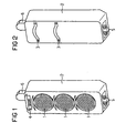
- Figures 1 and 2 is in a front and a rear view the outer shape of a signal generator for road traffic shown. This seems conventional at first glance Signal transmitter has three light signal transmitter 1 for red, Yellow or green light on the front of his housing 2 are assigned. Also, he is like usual siren on one not shown signal mast by means of clamps 3 to fix. But exhausted in its appearance the match with signalers that everyone out knows the traffic.
- a first detector arranged. This is formed in this example as a passive infrared detector 4 and in this orientation intended for vehicle movements to capture the - seen in the direction of traffic - lie in front of the signal generator.
- In the area of the bottom of the housing 1 further detectors are provided in this Example as video cameras 5 are formed.
- an antenna 6 is arranged, which serves as a transmitting / receiving antenna is trained.
- FIG. 3 illustrates that this processor unit 8 with input / output devices 81 is equipped and about this with their environment communicated.
- the processor unit 8 call or receive control signals from the signal controller 7, with which it is possible to have a faultless functional state to monitor the light sensor 1.
- the embodiment of Figure 3 is also based, that the processor unit 8 also that of the detectors 4 and 5 detected information about the current traffic condition is supplied.
- the infrared detector 4 or the video cameras 5 each assigned a detector unit 9 and 10 respectively. These prepare the signals from the connected Infrared detector 4 and the video cameras 5 on. details
- the expert is familiar because a traffic monitoring by means of infrared detectors or video cameras themselves as may be assumed to be known.
- z. B. also for the evaluation of recordings of the video cameras one Variety of design options, their use of the Structure of the respective traffic control or traffic control system in which a single Signalers only one of possibly many peripheral Represents modules.
- the processor unit 8 not only with the in the signal generator itself integrated units in combination but is also equipped to continue with her spatially separate facilities one Traffic signal system or a traffic guidance system information exchange.
- a communication device 11 connected as a bidirectional remote data transmission device is to be considered and in this example as a radio transmitter / receiver via the connected antenna 6 with the environment communicates.
- this communication device 11 as Interface to surrounding facilities in conjunction with a corresponding transmitting / receiving device as a data transmission device designed for an infrared connection be.
- a wired data transmission via connected data lines, possibly also over it shared supply lines would be conceivable, as in FIG. 3 alternatively by a dashed line Connection of the communication device 11 to a cable 12 is indicated.
- a traffic signal system for example, traffic guidance at only one intersection or junction, without being externally connected, on its own and only equipped with a limited number of signalers.
- a device control housed in a control box, in the area the traffic signal system set up and to the individual signal generator connected via underground cables. about this cable connection provides the device control by predetermined signal program specified individual control signals to the connected signal generator or their Signal controls.
- the processor unit of one of Signal transmitter of the traffic signal system takes over as the main controller the function of the conventionally separately set up Device control, the processor units of the other signal generator
- the traffic signal system will be controlled by this main controller in the manner of a "master-slave" configuration.
- the required communication between the processor units the signal generator is preferably wireless via a radio or Infratrotitati, it is in itself but also possible already existing line connections to use for this data exchange.
- traffic signal systems of the described above as local subsystems as the main control of the respective subsystem functioning processor unit in addition to the functions described also exchanges data with a central traffic computer.
- the central traffic computer are those of the individual Subsystem supplied recorded occupancy data and evaluated. Dependent on this is the main control of each one Subsystem so activated that after this one adapted signal program in turn controls the subsystem.
Landscapes
- Physics & Mathematics (AREA)
- General Physics & Mathematics (AREA)
- Traffic Control Systems (AREA)
Abstract
Description
Die Erfindung bezieht sich auf eine Verkehrssignalanlage gemäß dem Oberbegriff des Patentanspruches 1.The invention relates to a traffic signal system according to the preamble of claim 1.
Eine für sich allein stehende Verkehrssignalanlage, beispielsweise zur Regelung des Verkehrs an einer Straßenkreuzung, die lediglich mit an deren Zufahrten installierten, nach einem fest vorgegebenen Signalprogramm arbeitenden Signalgebern ausgerüstet ist, ist heute wohl nur noch als herkömmlich zu bezeichnen. Bei einem dichten Straßennetz und hohem Verkehrsaufkommen, insbesondere in Ballungsräumen, müssen Anlagen zur Steuerung des Straßenverkehrs wesentlich komplexere Aufgaben erfüllen. So werden beispielsweise Verkehrssignalanlagen einzelner Kreuzungen miteinander vernetzt, um den Verkehr in einer Hauptverkehrsader flüssig halten zu können, insbesondere also mehrfaches Anhalten und Wiederanfahren der Kraftfahrzeuge möglichst zu vermeiden. Ferner werden modernen Verkehrssignalanlagen häufig Mittel zur Fahrzeugdetektion wenigstens in Richtung der maßgebenden Verkehrsströme zugeordnet, um eine bedarfsabhängige Verkehrslenkung zu ermöglichen.A stand-alone traffic signal system, for example for regulating traffic at a road intersection, which are installed only on their driveways, according to a fixed predetermined signal program operating signal generators equipped is today probably only as conventional to call. In a dense road network and high Traffic, especially in agglomerations Road traffic control systems much more complex Fulfill tasks. For example, traffic signal systems cross-linked with each other to the To be able to keep traffic flowing in a main traffic artery, So in particular multiple stops and restarting the To avoid motor vehicles as much as possible. Furthermore, modern Traffic signal systems often means for vehicle detection at least assigned in the direction of the authoritative traffic flows, to enable on-demand traffic management.
Aus US-A-5 777 564 ist als ein Beispiel für eine moderne Verkehrssignalanlage bekannt, wie man mit Hilfe von Fahrzeugdetektoren, die im Bereich einer oder mehrerer Kreuzungen eines Verkehrsweges angeordnet sind, den Verkehrsfluß durch die einzelnen Kreuzungen bedarfsabhängig steuern und damit optimieren kann. Wie dieses Beispiel lehrt, ist der technische Aufwand zur Bewältigung dieser Anforderungen beträchtlich. Neben den eigentlichen Signalgebern und deren Steuerungen werden Fahrzeugdetektoren benötigt, die vielfach als in die Fahrbahnen eingelassene Induktionsschleifen, aber beispielsweise auch als passive Infrarot- oder Verkehrsradardetektoren ausgebildet sind. Zur Verkehrsermittlung können daneben auch Videokameras eingesetzt werden. From US-A-5 777 564 is as an example of a modern traffic signal system known how to use vehicle detectors, in the area of one or more intersections of a Traffic route are arranged, the flow of traffic through the Control individual intersections as needed and thus optimize them can. As this example teaches, the technical Effort to cope with these requirements considerably. In addition to the actual signalers and their controllers Vehicle detectors are needed many times as in the Lanes embedded induction loops, but for example also as passive infrared or traffic radar detectors are formed. For traffic determination can also next Video cameras are used.
Die von diesen Sensoren abgegebenen Verkehrsinformationen müssen aufbereitet und verarbeitet werden, um daraus ein auf die aktuellen Verkehrsströme abgestimmtes Signalprogramm abzuleiten, mit dem schließlich die verschiedenen Signalgeber der Verkehrssignalanlage betrieben werden. Neben einem zentralisiert organisierten oder auch dezentral aufgebauten Rechnersystem werden naturgemäß auch entsprechende Übertragungswege von den peripheren Einheiten zum Rechnersystem bzw. vom Rechnersystem zu den peripheren Steuerungen und Einheiten benötigt. Neben den eigentlichen Versorgungsleitungen für die einzelnen Einheiten der Verkehrssignalanlage sind deshalb auch entsprechende Leitungsverbindungen zur Informationsübertragung erforderlich. Es ist ersichtlich, daß gerade auch der Betrieb moderner Verkehrssignalanlagen mit einem erheblichen technischen Investitionsaufwand verbunden ist.The traffic information provided by these sensors need to be processed and processed to make it one derive the current traffic streams tuned signal program, with that finally the different signalers the traffic signal system to be operated. In addition to a centralized Organized or decentralized computer system naturally also become corresponding transmission paths from the peripheral units to the computer system or from Computer system to the peripheral controllers and units needed. In addition to the actual supply lines for the individual units of the traffic signal system are therefore also corresponding line connections for information transmission required. It can be seen that especially the Operation of modern traffic signal systems with a considerable technical investment.
Dokument EP-A-0, 296, 426 betrifft ein Datenübertragungssystem für Straßenverkehrssignalanlagen, welches zur Steuerung und Femversorgung von Kreuzungsgeräten der Straßenverkehrssignalanlage von einem zentralen Verkehrsrechner aus dient.Document EP-A-0, 296, 426 relates to a data transmission system for Road signaling systems, which for the control and Femversorgung of Intersection devices of the traffic signal system from a central traffic computer out serves.
Der vorliegenden Erfindung liegt daher die Aufgabe zugrunde, eine Verkehrssignalanlage anzugeben, die bei geringem Planungs- und Installationsaufwand in flexibler Weise an unterschiedliche Erfordernisse anzupassen ist.The present invention is therefore based on the object indicate a traffic signaling system which, with little planning and installation effort in a flexible manner to different Needs to be adjusted.
Bei einer Verkehrssignalanlage der eingangs genannten Art wird diese eine Aufgabe erfindungsgemäß durch die im Kennzeichen des Patentanspruches 1 beschriebenen Merkmale gelöst.In a traffic signal system of the type mentioned This is an object of the invention by the in the license plate solved the features described in claim 1.
Bei einem erfindungsgemäß ausgebildeten Signalgeber werden technologische Fortschritte, die kleinere Bauformen ermöglichen, mit Vorteil ausgenutzt. Dabei wird von dem Gedanken abgegangen, daß ein Signalgeber, sichtbar an einem Mast aufgehängt, einzig und allein der Funktion dient, optische Signale auszusenden und von ihm nicht zu weit entfernt eine Gerätesteuerung aufgestellt ist, über die ihm für seinen Betrieb die erforderliche elektrische Energie und Steuerungsinformation zugeführt werden. Herkömmliche Signalgeber dieser Art besitzen allenfalls eine Signalansteuerung, durch die alternativ die einzelnen Lichtzeichengeber, ausgelöst durch die Gerätesteuerung, aktiviert werden. In a signal generator designed according to the invention technological advances that enable smaller designs, exploited with advantage. It is departed from the idea, that a signal generator, suspended from a mast, solely the function serves, optical signals to send out and from him not too far away a device control is set up about him for his operation the required electrical energy and control information be supplied. Conventional signal generator of this type possibly have a signal control, by the alternative the individual light signals, triggered by the Device control, be activated.
Mit einem erfindungsgemäß ausgebildeten Signalgeber lassen sich dagegen sowohl kleinere als auch komplex aufgebaute Verkehrssignalanlagen erstellen, deren Aufbau, vor allem auch hinsichtlich der Steuerung der Signalgeber, statt einer im wesentlichen zentral ausgerichteten eine mehr dezentral organisierte Struktur besitzt. Dies wird dadurch erreicht, daß mehr "Intelligenz" in die Peripherie der Verkehrssignalanlage, also in die Signalgeber selbst verlegt ist. So wird aus dem herkömmlichen Signalgeber, der als ein passives Gerät zu interpretieren ist, ein aktives Gerät, in dem bereits wesentliche Teile der Steuerungsfunktionen selbständig ausgeführt werden.With a trained according to the invention signal generator on the other hand, both smaller and more complex traffic signal systems create, their structure, especially in terms of control of the signalers, instead of one in the essentially centrally organized one more decentralized organized Owns structure. This is achieved in that more "intelligence" in the periphery of the traffic signal system, So moved into the signal generator itself. That's how it turns out the conventional auto switch that acts as a passive device too is an active device in which is already essential Parts of the control functions executed independently become.
Gemäß einer der Weiterbildungen dieser Lösung ist in den Signalgeber unmittelbar ein Steuerrechner integriert, der auch so ausgebildet sein kann, daß er als periphere Steuerung für weitere Signalgeber einsetzbar ist, die mit ihm jeweils über Datenübertragungseinrichtungen vernetzbar sind. Dieser Steuerrechner übernimmt dann für die in der Verkehrssignalanlage mit ihm vernetzten weiteren Signalgeber die Funktion der Hauptsteuerung, wobei die entsprechenden Steuerrechner der weiteren Signalgeber von dieser Hauptsteuerung abhängig geführt sind. Eine kleinere Verkehrssignalanlage, beispielsweise für eine einzelne Straßenkreuzung kann damit als autarke Anlage so aufgebaut werden, daß einer ihrer Signalgeber mit seinem Steuerrechner das Signalprogramm für die gesamte Verkehrssignalanlage ausführt, nach dem auch die übrigen Signalgeber arbeiten. Größere Verkehrssignalanlagen können, auf dieser Struktur aufbauend, aus einer Mehrzahl von Gruppen jeweils miteinander vernetzter Signalgeber bestehen, wobei ein zentraler Verkehrsrechner die Systemsteuerung übernimmt und über Datenübertragungsleitungen mit den Steuerrechnern kommuniziert, denen in der jeweiligen Gruppe von Signalgebern die Funktion einer Hauptsteuerung zugewiesen ist.According to one of the developments of this solution is in the signal generator directly integrated into a control computer, too can be designed so that it as a peripheral control for Another signal generator can be used, with him over each Data transmission devices are networked. This control computer then takes over for the traffic signal system networked with him further signal generator the function of Main control, the corresponding control computer of the further signal generator led by this main control dependent are. A smaller traffic signal system, for example for a single intersection can thus be self-sufficient Plant be constructed so that one of their signal generator with his control computer, the signal program for the entire traffic signal system after which also the other signal transmitters work. Larger traffic signal systems can, on building on this structure, from a plurality of groups respectively interconnected signaling device consist, with a central traffic computer takes over the system control and communicates with the control computers via data transmission lines, those in the respective group of signalers the Assigned to a main control function.
Gemäß einer weiteren vorteilhaften Weiterbildung der Erfindung ist in den Signalgeber selbst mindestens ein Fahrzeugdetektor integriert. Damit ist jeder Signalgeber einer damit ausgestatteten Verkehrssignalanlage - in Doppelfunktion - sowohl ein gesteuerter Lichtzeichengeber als auch ein Gerät zum Feststellen momentaner Fahrzeugbewegungen in seinem Erfassungsbereich. Über seine(n) Fahrzeugdetektor(en) ermittelte Fahrzeuginformationen können im eigenen Steuerrechner, fallweise in dem Steuerrechner, der für eine Gruppe von Signalgebern die Funktion der Hauptsteuerung ausführt, verarbeitet werden. Bei einer autarken Verkehrssignalanlage ist es somit möglich, daraus ein dem momentanen Bedarf angepaßtes Signalprogramm nur für diese Verkehrssignalanlage abzuleiten. In größeren, durch einen zentralen Verkehrsrechner gesteuerten Anlagen wird die in den einzelnen Gruppen von miteinander lokal vernetzten Signalgebern vorverarbeitete Information über die lokale Verkehrssituation durch den zentralen Verkehrsrechner abgerufen bzw. diesem angeboten, um dort zentral weiterverarbeitet zu werden, beispielsweise um den Verkehrsfluß längs einer Hauptverkehrsader bedarfsgerecht zu lenken.According to a further advantageous embodiment of the invention is in the signal generator itself at least one vehicle detector integrated. So every signaler is one with it equipped traffic signal system - in dual function - both a controlled light sensor as well as a device for Detecting momentary vehicle movements in its detection area. Determined via his vehicle detector (s) Vehicle information can be in your own tax calculator, on a case-by-case basis in the control computer, for a group of signalers performs the function of the main controller, processed become. In a self-sufficient traffic signal system, it is thus possible, from this a signal program adapted to the current requirement derive only for this traffic signal system. In larger, controlled by a central traffic computer Attachments become local in each group of each other Networked signal transmitters preprocessed information about the local traffic situation through the central traffic computer retrieved or offered to be centrally processed there to become, for example, the traffic flow steer along a main traffic artery as needed.
Ausführungsbeispiele und weitere vorteilhafte Ausgestaltungen
der Erfindung werden im folgenden anhand der Zeichnung näher
erläutert, dabei zeigt:
In Figur 1 und 2 ist in einer Front- bzw. einer Rückansicht
die äußere Form eines Signalgebers für den Straßenverkehr
dargestellt. Dieser auf den ersten Blick herkömmlich erscheinende
Signalgeber weist drei Lichtzeichengeber 1 für Rot-,
Gelb- bzw. Grünlicht auf, die der Frontseite seines Gehäuses
2 zugeordnet sind. Auch ist er wie übliche Signalgeber an einem
nicht dargestellten Signalmast mittels Schellen 3 zu befestigen.
Damit erschöpft sich aber in seinem Erscheinungsbild
die Übereinstimmung mit Signalgebern, die jedermann aus
dem Straßenverkehr kennt.In Figures 1 and 2 is in a front and a rear view
the outer shape of a signal generator for road traffic
shown. This seems conventional at first glance
Signal transmitter has three light signal transmitter 1 for red,
Yellow or green light on the front of his
Denn in der Frontansicht von Figur 1 ist ferner oberhalb der
Lichtzeichengeber 1 ein erster Detektor angeordnet. Dieser
ist in diesem Beispiel als passiver Infrarotdetektor 4 ausgebildet
und bei dieser Ausrichtung dafür vorgesehen, Fahrzeugbewegungen
zu erfassen, die - in Verkehrsrichtung gesehen
- vor dem Signalgeber liegen. Im Bereich des Bodens des Gehäuses
1 sind weitere Detektoren vorgesehen, die in diesem
Beispiel als Videokameras 5 ausgebildet sind. Wie ein Vergleich
von Figur 1 mit Figur 2 zeigt, sind diese Detektoren
sowohl frontseitig als auch rückseitig ausgerichtet, so daß
damit Fahrzeugbewegungen sowohl für die auf den Signalgeber
zufließende als auch die abfließende Verkehrsrichtung zu erfassen
sind. Aus der Deckfläche des Gehäuses 1 hervorstehend,
ist eine Antenne 6 angeordnet, die als Sende-/Empfangsantenne
ausgebildet ist. Schon diese rein äußerlich erkennbaren Merkmale
zeigen, daß mit dem in den Figuren 1 und 2 dargestellten
Signalgeber eine Doppelfunktion als optischer Lichtzeichengeber
der gewohnten Art, darüberhinaus aber auch als Mittel zum
Erfassen des momentanen Verkehrsstromes in seinem Erfassungsbereich
erfüllt ist.Because in the front view of Figure 1 is also above the
Light sensor 1 a first detector arranged. This
is formed in this example as a passive infrared detector 4
and in this orientation intended for vehicle movements
to capture the - seen in the direction of traffic
- lie in front of the signal generator. In the area of the bottom of the housing
1 further detectors are provided in this
Example as
Aus Figur 3, die schematisch in einem Blockschaltbild den inneren
Aufbau des Signalgebers nach Figur 1 bzw. 2 wiedergibt,
wird jedoch noch deutlicher, wofür dieser konzipiert ist. In
diesem in Figur 3 dargestellten Querschnitt durch das Gehäuse
2 des Signalgebers sind zunächst die Lichtzeichengeber 1 sowie
die ferner bereits erwähnten Detektoren, wie der Infrarotdetektor
4 und die Videokameras 5, schließlich auch die
Antenne 6 zu erkennen. Den Lichtzeichengebern 1 ist eine in
einem Block dargestellte Signalansteuerung 7 der Art zugeordnet,
die auch herkömmlichen Signalgebern anzutreffen ist.From Figure 3, which shows schematically in a block diagram the inner
Structure of the signal generator according to Figure 1 or 2 reproduces,
however, it becomes even clearer what it is designed for. In
this cross section through the housing shown in Figure 3
2 of the signal generator are initially the light sensor 1 and
the already mentioned detectors, such as the infrared detector
4 and the
Im Gegensatz dazu ist aber die in konventionellen Verkehrssignalanlagen
von dem Signalgeber getrennt aufgestellte Gerätesteuerung,
in Figur 3 als Prozessoreinheit 8 dargestellt,
in das Gehäuse 1 des Signalgebers integriert. Figur 3 illustriert,
daß diese Prozessoreinheit 8 mit Ein-/Ausgabeeinrichtungen
81 ausgestattet ist und über diese mit ihrer Umwelt
kommuniziert. Dies bezieht sich zunächst auf die Signalansteuerung
7 der Lichtzeichengeber 1. In Figur 3 ist die Verbindung
zwischen der Prozessoreinheit 8 und der Signalansteuerung
7 als bidirektionale Verbindung dargestellt. Damit ist
angedeutet, daß die Prozessoreinheit 8 an die Signalansteuerung
sowohl Steuersignale überträgt, die die Lichtzeichengeber
1 entsprechend einem bestimmten Signalprogramm selektiv
aktivieren. In der Gegenrichtung kann die Prozessoreinheit 8
von der Signalansteuerung 7 Kontrollsignale abrufen bzw. empfangen,
mit denen es möglich ist, einen fehlerfreien Funktionszustand
der Lichtzeichengeber 1 zu überwachen.In contrast, however, is that in conventional traffic signal systems
separate from the signal generator device control,
shown in Figure 3 as a
Dem Ausführungsbeispiel von Figur 3 ist ferner zugrunde gelegt,
daß der Prozessoreinheit 8 auch die von den Detektoren
4 bzw. 5 erfaßte Information über den aktuellen Verkehrszustand
zugeführt wird. Dazu ist dem Infrarotdetektor 4 bzw.
den Videokameras 5 jeweils eine Detektoreinheit 9 bzw. 10 zugeordnet.
Diese bereiten die Signale von dem angeschlossenen
Infrarotdetektor 4 bzw. den Videokameras 5 auf. Einzelheiten
dazu sind dem Fachmann geläufig, da eine Verkehrsüberwachung
mittels Infrarotdetektoren oder auch Videokameras an sich als
bekannt vorausgesetzt werden darf. Wie bekannt, besteht z. B.
auch für die Auswertung von Aufnahmen der Videokameras eine
Vielzahl von Gestaltungsmöglichkeiten, deren Einsatz von der
Struktur des jeweiligen Verkehrsüberwachungs-
bzw. Verkehrslenkungssystems abhängt, in dem ein einzelner
Signalgeber lediglich eine der möglicherweise vielen peripheren
Module darstellt.The embodiment of Figure 3 is also based,
that the
Ein weiteres Merkmal des hier beschriebenen Signalgebers besteht
darin, daß die Prozessoreinheit 8 nicht nur mit den in
den Signalgeber selbst integrierten Baueinheiten in Verbindung
steht, sondern darüberhinaus dafür ausgerüstet ist, weiterhin
mit von ihr räumlich getrennten Einrichtungen einer
Verkehrssignalanlage bzw. eines Verkehrslenkungssystems Informationen
auszutauschen. Im Ausführungsbeispiel nach Figur
3 ist zu diesem Zweck an die Ein-/Ausgabeeinrichtungen 81 der
Prozessoreinheit 8 eine Kommunikationseinrichtung 11 angeschlossen,
die als eine bidirektionale Datenfernübertragungseinrichtung
anzusehen ist und in diesem Beispiel als Funksender-/empfänger
über die angeschlossene Antenne 6 mit der Umwelt
in Verbindung steht. Alternativ könnte - wie dem Fachmann
einleuchtet - diese Kommunikationseinrichtung 11 als
Schnittstelle zu umgebenden Einrichtungen in Verbindung mit
einer entsprechenden Sende-/Empfangseinrichtung auch als Datenübertragungseinrichtung
für eine Infrarotverbindung ausgebildet
sein. Auch eine leitungsgebundene Datenübertragung
über angeschlossene Datenleitungen, eventuell auch über dafür
mitbenutzte Versorgungsleitungen wäre denkbar, wie in Figur 3
als Alternative durch einen in unterbrochenen Linien gezeichneten
Anschluß der Kommunikationseinrichtung 11 an ein Leitungskabel
12 angedeutet ist.Another feature of the signal generator described here is
in that the
Es ist einsehbar, daß diese Funktion der Kommunikationsfähigkeit
des Signalgebers mit seiner Systemumwelt, als Variante
zum vorstehend beschriebenen Ausführungsbeispiel auch so zu
realisieren ist, daß die Komunikationseinrichtung 11 nicht
nur eine durch die Prozessoreinheit 8 gesteuerte Schnittstelleneinrichtung
bildet, sondern daß die Abwicklung von Ein/Ausgabeprozeduren
in die Kommunikationseinrichtung 11 selbst
verlegt ist. Dabei könnten einzelne der Detektoreinheiten 9
bzw. 10 unmittelbar an die Kommunikationseinrichtung 11 als
von dieser gesteuerte periphere Einheiten angeschlossen sein.It can be seen that this function of communication skills
the signal generator with its system environment, as a variant
to the embodiment described above also so
realize that the
Losgelöst von derartigen Ausgestaltungen seiner elektronischen Schaltung ermöglicht der beschriebene multifunktionale Signalgeber in flexibler Weise eine Vielzahl von Ausführungsformen von Verkehrssignalanlagen zu realisieren. Im einfachen Fall steht eine Verkehrssignalanlage, beispielsweise zur Verkehrslenkung an nur einer Straßenkreuzung oder Einmündung, ohne extern vernetzt zu sein, für sich allein und ist lediglich mit einer beschränkten Anzahl von Signalgebern ausgestattet. Bei einer konventionellen Lösung würde eine Gerätesteuerung, in einem Schaltkasten untergebracht, im Bereich der Verkehrssignalanlage aufgestellt und an die einzelnen Signalgeber über im Erdreich verlegte Kabel angeschlossen. Über diese Kabelverbindung liefert die Gerätesteuerung durch ein vorgegebenes Signalprogramm festgelegte individuelle Steuersignale an die angeschlossenen Signalgeber bzw. deren Signalansteuerungen.Detached from such configurations of its electronic Circuit allows the described multifunctional Signalers in a flexible manner a variety of embodiments to realize traffic signal systems. Im simple Case is a traffic signal system, for example, traffic guidance at only one intersection or junction, without being externally connected, on its own and only equipped with a limited number of signalers. In a conventional solution, a device control, housed in a control box, in the area the traffic signal system set up and to the individual signal generator connected via underground cables. about this cable connection provides the device control by predetermined signal program specified individual control signals to the connected signal generator or their Signal controls.
Davon unterscheidet sich eine Verkehrssignalanlage, die mit Signalgebern der vorstehend beschriebenen Ausführungsformen ausgerüstet ist, grundlegend. Die Prozessoreinheit eines der Signalgeber der Verkehrssignalanlage übernimmt als Hauptsteuerung die Funktion der konventionell separat aufgestellten Gerätesteuerung, die Prozessoreinheiten der übrigen Signalgeber der Verkehrssignalanlage werden durch diese Hauptsteuerung nach Art einer "Master-Slave" - Konfiguration geführt. Die dazu erforderliche Kommunikation zwischen den Prozessoreinheiten der Signalgeber erfolgt vorzugsweise kabellos über eine Funk- oder Infratrotverbindung, wobei es an sich aber auch möglich ist, bereits vorhandene Leitungsverbindungen für diesen Datenaustausch zu nutzen. Sind die Signalgeber in erforderlichem Umfang auch mit Detektoren ausgerüstet, so lassen sich im Bereich dieser Verkehrssignalanlage auch Informationen zur aktuellen Verkehrsbelegung erfassen und in der als Hauptsteuerung ausgebildeten Prozessoreinheit verarbeiten. Diese ist damit befähigt, selbsttätig ein an die aktuelle Verkehrssituation angepaßtes Signalprogramm auszuwählen und die mit ihr vernetzten Signalgeber entsprechend anzusteuern.This is different from a traffic signal system with Signaling of the embodiments described above equipped, basic. The processor unit of one of Signal transmitter of the traffic signal system takes over as the main controller the function of the conventionally separately set up Device control, the processor units of the other signal generator The traffic signal system will be controlled by this main controller in the manner of a "master-slave" configuration. The required communication between the processor units the signal generator is preferably wireless via a radio or Infratrotverbindung, it is in itself but also possible already existing line connections to use for this data exchange. Are the signalers to the extent required also equipped with detectors, so can be in the area of this traffic signal system also information to record the current traffic allocation and in process the processing unit formed as a main controller. This is thus capable of automatically one to the current Traffic situation adapted signal program to select and to control the connected with their signal generator accordingly.
In umfangreicheren Verkehrssignalanlagen, die beispielsweise im Zuge einer Hauptverkehrsader liegen, allgemeiner den Verkehr über mehrere Straßenkreuzungen sowie eine Mehrzahl von Zu- bzw. Abfahrten lenken, werden Verkehrssignalanlagen der vorstehend beschriebenen Art als lokale Subsysteme organisiert, deren als Hauptsteuerung des jeweiligen Subsystems fungierende Prozessoreinheit neben den beschriebenen Funktionen ferner Daten mit einem zentralen Verkehrsrechner austauscht. Im zentralen Verkehrsrechner werden die von den einzelnen Subsystemen gelieferten Belegungsdaten erfaßt und ausgewertet. Davon abhängig wird die Hauptsteuerung jedes einzelnen Subsystems so aktiviert, daß diese nach einem daran angepaßten Signalprogramm ihrerseits das Subsystem steuert.In more extensive traffic signal systems, for example in the course of a main traffic artery, more generally the traffic over several intersections and a plurality of To steer on or departures, traffic signal systems of the described above as local subsystems, as the main control of the respective subsystem functioning processor unit in addition to the functions described also exchanges data with a central traffic computer. In the central traffic computer are those of the individual Subsystem supplied recorded occupancy data and evaluated. Dependent on this is the main control of each one Subsystem so activated that after this one adapted signal program in turn controls the subsystem.
Daraus wird deutlich, daß sich erfindungsgemäß ausgebildete Signalgeber in weitem Umfang für unterschiedliche Lösungen sowohl bei kleinen, autark arbeitenden Verkehrssignalanlagen als auch bei sehr komplexen Straßenverkehrssystemen einsetzen lassen. Der Planungs- und Installationsaufwand für Verkehrssignalanlagen reduziert sich dabei erheblich, da die Signalgeber bei derartigen Systemen als periphere Einheiten zu interpretieren sind, die nahezu beliebig hinzugefügt bzw. organisatorisch in das System bzw. ein Subsystem eingegliedert werden können, wobei es keiner Grabungsarbeiten zur Kabelverlegung bedarf, wenn die systemimmanent gegebene Möglichkeit kabelloser Datenverbindungen genutzt wird.It is clear that inventively designed Signal generators on a wide scale for different solutions both in small, self-sufficient traffic signal systems as well as very complex road traffic systems to let. The planning and installation effort for traffic signal systems is reduced considerably, as the signal generator in such systems as peripheral units too interpret that are added almost arbitrarily or organisationally integrated into the system or a subsystem where there is no excavation work for cable laying needed, if the system inherent possibility wireless data connections is used.
Claims (11)
- Traffic signal system which comprises a plurality of signal transmitters which contain light signal transmitters (1) and have a housing (2) and a control unit (7, 8) for actuating the signal transmitters according to a predefined signal program, characterized in that a control unit (7, 8) and a data transmission device (11) for communicating with other signal transmitters of the traffic signal system are integrated into the housing (2) of each signal transmitter.
- Traffic signal system according to Claim 1, characterized in that the control unit comprises a control computer (8) which executes the signal program and a signal actuator (7), assigned downstream of the latter, for the light signal transmitters (1).
- Traffic signal system according to Claim 2, characterized in that the control computer (8) of one of its signal transmitters is embodied as a peripheral controller for further signal transmitters of the traffic signal system which can be networked to it via the respective data transmission devices (11) of the individual signal transmitters.
- Traffic signal system according to Claim 3, characterized in that an external interface of the data transmission device (11) is embodied as a line-bound interface for connection to individual data lines (12) or to supply lines which are also used for transmitting data.
- Traffic signal system according to Claim 3, characterized in that the data transmission device (11) is embodied as a modem with a transceiver device (6) connected thereto.
- Traffic signal system according to Claim 5, characterized in that the transceiver device (6) is embodied as a radio antenna.
- Traffic signal system according to Claim 5, characterized in that the transceiver device (6) is embodied as an infrared transceiver.
- Traffic signal system according to one of Claims 1 to 7, characterized in that at least one vehicle detector (4 or 5) for detecting vehicles stopping in the sensing range of the respective signal transmitter is integrated into the housing (2) of each signal transmitter.
- Traffic signal system according to Claim 8, characterized in that the at least one vehicle detector (4 or 5) is embodied as a passive infrared detector, as a radar detector and/or as a video camera.
- Traffic signal system according to Claim 8 or 9, characterized in that an evaluation unit (9 or 10) is assigned to the vehicle detector (4 or 5) and has a communications link control computer (8) and/or to the data transmission device (11, 6) for exchanging data.
- Traffic signal system according to Claim 10, characterized in that said system forms, as a subsystem which controls itself at the local level, one of a plurality of identical subunits of a more extensive traffic control system in which a central traffic computer is provided which is embodied as a control computer for the main controllers (8), which are then subordinate, of the subunits or subsystems, and exchanges traffic data and/or control data with the latter via their devices (for example 6, 11) for exchanging data.
Applications Claiming Priority (2)
| Application Number | Priority Date | Filing Date | Title |
|---|---|---|---|
| DE19846229 | 1998-10-07 | ||
| DE19846229 | 1998-10-07 |
Publications (3)
| Publication Number | Publication Date |
|---|---|
| EP0992964A2 EP0992964A2 (en) | 2000-04-12 |
| EP0992964A3 EP0992964A3 (en) | 2000-10-04 |
| EP0992964B1 true EP0992964B1 (en) | 2005-12-21 |
Family
ID=7883723
Family Applications (1)
| Application Number | Title | Priority Date | Filing Date |
|---|---|---|---|
| EP99119128A Expired - Lifetime EP0992964B1 (en) | 1998-10-07 | 1999-10-05 | Signal indicator and traffic signal device equipped therewith |
Country Status (3)
| Country | Link |
|---|---|
| EP (1) | EP0992964B1 (en) |
| AT (1) | ATE313838T1 (en) |
| DE (1) | DE59912955D1 (en) |
Families Citing this family (6)
| Publication number | Priority date | Publication date | Assignee | Title |
|---|---|---|---|---|
| AU2003901485A0 (en) * | 2003-04-01 | 2003-04-17 | Wireless Traffic Technologies Pty Limited | Traffic control system |
| DE102005032719A1 (en) * | 2005-07-13 | 2007-01-25 | Siemens Ag | Traffic signal system, in particular for road traffic |
| DE102007047847B4 (en) * | 2007-11-22 | 2018-02-22 | Swarco Traffic Systems Gmbh | Traffic signal system with signal transmitters and a control device for controlling lights in the signalers |
| DE102008003439B4 (en) * | 2008-01-07 | 2009-09-17 | Siemens Aktiengesellschaft | Traffic signaling module, traffic signaling system and method of operating a traffic signaling system |
| DE102009015120B4 (en) | 2009-03-31 | 2011-06-16 | Siemens Aktiengesellschaft | Device for emitting light signals and for recording video images in traffic |
| GB2621617A (en) * | 2022-08-18 | 2024-02-21 | Srl Traffic Systems Ltd | Improvements in and relating to haul route junctions |
Family Cites Families (4)
| Publication number | Priority date | Publication date | Assignee | Title |
|---|---|---|---|---|
| US4857921A (en) * | 1986-05-30 | 1989-08-15 | Flagman, Inc. | Digital traffic control system |
| EP0296426B1 (en) * | 1987-06-26 | 1994-04-20 | Siemens Aktiengesellschaft | Data transmitting system for road traffic signal devices |
| US4908615A (en) * | 1987-06-26 | 1990-03-13 | Texas Instruments Incorporated | Traffic light control system and method |
| GB2295475A (en) * | 1994-11-25 | 1996-05-29 | Barry Soden | Signal control system |
-
1999
- 1999-10-05 EP EP99119128A patent/EP0992964B1/en not_active Expired - Lifetime
- 1999-10-05 DE DE59912955T patent/DE59912955D1/en not_active Expired - Lifetime
- 1999-10-05 AT AT99119128T patent/ATE313838T1/en not_active IP Right Cessation
Also Published As
| Publication number | Publication date |
|---|---|
| DE59912955D1 (en) | 2006-01-26 |
| EP0992964A2 (en) | 2000-04-12 |
| ATE313838T1 (en) | 2006-01-15 |
| EP0992964A3 (en) | 2000-10-04 |
Similar Documents
| Publication | Publication Date | Title |
|---|---|---|
| EP3231690A1 (en) | Method and device for assisting a parking manoeuvre | |
| DE4111736C1 (en) | ||
| DE3417956C2 (en) | ||
| WO1999066473A1 (en) | Automation system with radio sensor | |
| EP0992964B1 (en) | Signal indicator and traffic signal device equipped therewith | |
| EP0811528B1 (en) | Control installation | |
| CH664462A5 (en) | COUPLING DEVICE FOR A FOCUS. | |
| DE10142250A1 (en) | Traffic flow control system, e.g. for control of traffic lights, is based on local collection and processing of traffic data for control of traffic within a limited range so that less complex hardware can be used | |
| EP1606785B1 (en) | Airportlighting unit and system | |
| EP1288883B1 (en) | Method and apparatus for controlling a system of several traffic signals | |
| DE102012220956A1 (en) | Detection system for an automated vehicle | |
| EP0424664A2 (en) | Device for the transmission of control information to a rail vehicle | |
| DE19906095A1 (en) | Circuit for electrical networking of sensors and /or actuators in motor vehicle, has actuator commands and sensor signals modulated onto voltage supply signal for sensors/actuators | |
| EP1246150A2 (en) | Fire alarm system | |
| DE10158678B4 (en) | Mobile traffic signal system and method for its control | |
| DE2758698C2 (en) | Device for outputting switching signals in motor vehicles | |
| DE4307486A1 (en) | Traffic control device | |
| DE4334980C2 (en) | Input-output element for hydraulic applications | |
| EP3528226B1 (en) | System device for operation in a wireless network | |
| DE102017002061A1 (en) | Control unit for a vehicle and vehicle with such a control unit | |
| DE3209753C2 (en) | Control device for operating an information device | |
| DE10023167B4 (en) | Passive infrared motion detectors | |
| EP0995180B1 (en) | Method and device for controlling light signal installations in accordance with traffic flows | |
| DE4428822C1 (en) | Method and device for warning people in the track area | |
| DE19648130A1 (en) | Traffic information system using roadside devices |
Legal Events
| Date | Code | Title | Description |
|---|---|---|---|
| PUAI | Public reference made under article 153(3) epc to a published international application that has entered the european phase |
Free format text: ORIGINAL CODE: 0009012 |
|
| AK | Designated contracting states |
Kind code of ref document: A2 Designated state(s): AT BE CH CY DE DK ES FI FR GB GR IE IT LI LU MC NL PT SE |
|
| AX | Request for extension of the european patent |
Free format text: AL;LT;LV;MK;RO;SI |
|
| PUAL | Search report despatched |
Free format text: ORIGINAL CODE: 0009013 |
|
| AK | Designated contracting states |
Kind code of ref document: A3 Designated state(s): AT BE CH CY DE DK ES FI FR GB GR IE IT LI LU MC NL PT SE |
|
| AX | Request for extension of the european patent |
Free format text: AL;LT;LV;MK;RO;SI |
|
| 17P | Request for examination filed |
Effective date: 20010305 |
|
| AKX | Designation fees paid |
Free format text: AT BE CH CY DE DK ES FI FR GB GR IE IT LI LU MC NL PT SE |
|
| 17Q | First examination report despatched |
Effective date: 20030509 |
|
| GRAP | Despatch of communication of intention to grant a patent |
Free format text: ORIGINAL CODE: EPIDOSNIGR1 |
|
| GRAS | Grant fee paid |
Free format text: ORIGINAL CODE: EPIDOSNIGR3 |
|
| GRAA | (expected) grant |
Free format text: ORIGINAL CODE: 0009210 |
|
| AK | Designated contracting states |
Kind code of ref document: B1 Designated state(s): AT BE CH CY DE DK ES FI FR GB GR IE IT LI LU MC NL PT SE |
|
| PG25 | Lapsed in a contracting state [announced via postgrant information from national office to epo] |
Ref country code: IT Free format text: LAPSE BECAUSE OF FAILURE TO SUBMIT A TRANSLATION OF THE DESCRIPTION OR TO PAY THE FEE WITHIN THE PRESCRIBED TIME-LIMIT;WARNING: LAPSES OF ITALIAN PATENTS WITH EFFECTIVE DATE BEFORE 2007 MAY HAVE OCCURRED AT ANY TIME BEFORE 2007. THE CORRECT EFFECTIVE DATE MAY BE DIFFERENT FROM THE ONE RECORDED. Effective date: 20051221 Ref country code: IE Free format text: LAPSE BECAUSE OF FAILURE TO SUBMIT A TRANSLATION OF THE DESCRIPTION OR TO PAY THE FEE WITHIN THE PRESCRIBED TIME-LIMIT Effective date: 20051221 Ref country code: FI Free format text: LAPSE BECAUSE OF FAILURE TO SUBMIT A TRANSLATION OF THE DESCRIPTION OR TO PAY THE FEE WITHIN THE PRESCRIBED TIME-LIMIT Effective date: 20051221 |
|
| REG | Reference to a national code |
Ref country code: GB Ref legal event code: FG4D Free format text: NOT ENGLISH |
|
| REG | Reference to a national code |
Ref country code: CH Ref legal event code: NV Representative=s name: SIEMENS SCHWEIZ AG Ref country code: CH Ref legal event code: EP |
|
| REG | Reference to a national code |
Ref country code: IE Ref legal event code: FG4D Free format text: LANGUAGE OF EP DOCUMENT: GERMAN |
|
| REF | Corresponds to: |
Ref document number: 59912955 Country of ref document: DE Date of ref document: 20060126 Kind code of ref document: P |
|
| GBT | Gb: translation of ep patent filed (gb section 77(6)(a)/1977) |
Effective date: 20060213 |
|
| PG25 | Lapsed in a contracting state [announced via postgrant information from national office to epo] |
Ref country code: SE Free format text: LAPSE BECAUSE OF FAILURE TO SUBMIT A TRANSLATION OF THE DESCRIPTION OR TO PAY THE FEE WITHIN THE PRESCRIBED TIME-LIMIT Effective date: 20060321 Ref country code: GR Free format text: LAPSE BECAUSE OF FAILURE TO SUBMIT A TRANSLATION OF THE DESCRIPTION OR TO PAY THE FEE WITHIN THE PRESCRIBED TIME-LIMIT Effective date: 20060321 Ref country code: DK Free format text: LAPSE BECAUSE OF FAILURE TO SUBMIT A TRANSLATION OF THE DESCRIPTION OR TO PAY THE FEE WITHIN THE PRESCRIBED TIME-LIMIT Effective date: 20060321 |
|
| PG25 | Lapsed in a contracting state [announced via postgrant information from national office to epo] |
Ref country code: ES Free format text: LAPSE BECAUSE OF FAILURE TO SUBMIT A TRANSLATION OF THE DESCRIPTION OR TO PAY THE FEE WITHIN THE PRESCRIBED TIME-LIMIT Effective date: 20060401 |
|
| PG25 | Lapsed in a contracting state [announced via postgrant information from national office to epo] |
Ref country code: PT Free format text: LAPSE BECAUSE OF FAILURE TO SUBMIT A TRANSLATION OF THE DESCRIPTION OR TO PAY THE FEE WITHIN THE PRESCRIBED TIME-LIMIT Effective date: 20060522 |
|
| REG | Reference to a national code |
Ref country code: IE Ref legal event code: FD4D |
|
| PGFP | Annual fee paid to national office [announced via postgrant information from national office to epo] |
Ref country code: NL Payment date: 20061006 Year of fee payment: 8 |
|
| PGFP | Annual fee paid to national office [announced via postgrant information from national office to epo] |
Ref country code: GB Payment date: 20061012 Year of fee payment: 8 |
|
| PG25 | Lapsed in a contracting state [announced via postgrant information from national office to epo] |
Ref country code: MC Free format text: LAPSE BECAUSE OF NON-PAYMENT OF DUE FEES Effective date: 20061031 |
|
| PLBE | No opposition filed within time limit |
Free format text: ORIGINAL CODE: 0009261 |
|
| STAA | Information on the status of an ep patent application or granted ep patent |
Free format text: STATUS: NO OPPOSITION FILED WITHIN TIME LIMIT |
|
| 26N | No opposition filed |
Effective date: 20060922 |
|
| EN | Fr: translation not filed | ||
| BERE | Be: lapsed |
Owner name: SIEMENS A.G. Effective date: 20061031 |
|
| PG25 | Lapsed in a contracting state [announced via postgrant information from national office to epo] |
Ref country code: FR Free format text: LAPSE BECAUSE OF FAILURE TO SUBMIT A TRANSLATION OF THE DESCRIPTION OR TO PAY THE FEE WITHIN THE PRESCRIBED TIME-LIMIT Effective date: 20070209 |
|
| GBPC | Gb: european patent ceased through non-payment of renewal fee |
Effective date: 20071005 |
|
| NLV4 | Nl: lapsed or anulled due to non-payment of the annual fee |
Effective date: 20080501 |
|
| PG25 | Lapsed in a contracting state [announced via postgrant information from national office to epo] |
Ref country code: LU Free format text: LAPSE BECAUSE OF NON-PAYMENT OF DUE FEES Effective date: 20061005 |
|
| PG25 | Lapsed in a contracting state [announced via postgrant information from national office to epo] |
Ref country code: NL Free format text: LAPSE BECAUSE OF NON-PAYMENT OF DUE FEES Effective date: 20080501 |
|
| PG25 | Lapsed in a contracting state [announced via postgrant information from national office to epo] |
Ref country code: GB Free format text: LAPSE BECAUSE OF NON-PAYMENT OF DUE FEES Effective date: 20071005 Ref country code: FR Free format text: LAPSE BECAUSE OF FAILURE TO SUBMIT A TRANSLATION OF THE DESCRIPTION OR TO PAY THE FEE WITHIN THE PRESCRIBED TIME-LIMIT Effective date: 20051221 Ref country code: CY Free format text: LAPSE BECAUSE OF FAILURE TO SUBMIT A TRANSLATION OF THE DESCRIPTION OR TO PAY THE FEE WITHIN THE PRESCRIBED TIME-LIMIT Effective date: 20051221 |
|
| REG | Reference to a national code |
Ref country code: CH Ref legal event code: PCAR Free format text: SIEMENS SCHWEIZ AG;INTELLECTUAL PROPERTY FREILAGERSTRASSE 40;8047 ZUERICH (CH) |
|
| PG25 | Lapsed in a contracting state [announced via postgrant information from national office to epo] |
Ref country code: BE Free format text: LAPSE BECAUSE OF FAILURE TO SUBMIT A TRANSLATION OF THE DESCRIPTION OR TO PAY THE FEE WITHIN THE PRESCRIBED TIME-LIMIT Effective date: 20061031 |
|
| PGFP | Annual fee paid to national office [announced via postgrant information from national office to epo] |
Ref country code: AT Payment date: 20090910 Year of fee payment: 11 |
|
| PGFP | Annual fee paid to national office [announced via postgrant information from national office to epo] |
Ref country code: CH Payment date: 20100112 Year of fee payment: 11 |
|
| PGFP | Annual fee paid to national office [announced via postgrant information from national office to epo] |
Ref country code: DE Payment date: 20091218 Year of fee payment: 11 |
|
| REG | Reference to a national code |
Ref country code: CH Ref legal event code: PL |
|
| PG25 | Lapsed in a contracting state [announced via postgrant information from national office to epo] |
Ref country code: CH Free format text: LAPSE BECAUSE OF NON-PAYMENT OF DUE FEES Effective date: 20101031 Ref country code: LI Free format text: LAPSE BECAUSE OF NON-PAYMENT OF DUE FEES Effective date: 20101031 |
|
| PG25 | Lapsed in a contracting state [announced via postgrant information from national office to epo] |
Ref country code: AT Free format text: LAPSE BECAUSE OF NON-PAYMENT OF DUE FEES Effective date: 20101005 |
|
| REG | Reference to a national code |
Ref country code: DE Ref legal event code: R119 Ref document number: 59912955 Country of ref document: DE Effective date: 20110502 |
|
| PG25 | Lapsed in a contracting state [announced via postgrant information from national office to epo] |
Ref country code: DE Free format text: LAPSE BECAUSE OF NON-PAYMENT OF DUE FEES Effective date: 20110502 |