EP0992724B1 - Kugelhahn - Google Patents
Kugelhahn Download PDFInfo
- Publication number
- EP0992724B1 EP0992724B1 EP99117114A EP99117114A EP0992724B1 EP 0992724 B1 EP0992724 B1 EP 0992724B1 EP 99117114 A EP99117114 A EP 99117114A EP 99117114 A EP99117114 A EP 99117114A EP 0992724 B1 EP0992724 B1 EP 0992724B1
- Authority
- EP
- European Patent Office
- Prior art keywords
- ball
- housing
- pin
- ball valve
- valve according
- Prior art date
- Legal status (The legal status is an assumption and is not a legal conclusion. Google has not performed a legal analysis and makes no representation as to the accuracy of the status listed.)
- Expired - Lifetime
Links
- 239000012530 fluid Substances 0.000 claims abstract description 33
- 238000003780 insertion Methods 0.000 description 3
- 230000037431 insertion Effects 0.000 description 3
- 238000007789 sealing Methods 0.000 description 3
- 230000015572 biosynthetic process Effects 0.000 description 1
- 239000002131 composite material Substances 0.000 description 1
- 230000001419 dependent effect Effects 0.000 description 1
- 230000007774 longterm Effects 0.000 description 1
- 238000004519 manufacturing process Methods 0.000 description 1
Images

Classifications
-
- F—MECHANICAL ENGINEERING; LIGHTING; HEATING; WEAPONS; BLASTING
- F16—ENGINEERING ELEMENTS AND UNITS; GENERAL MEASURES FOR PRODUCING AND MAINTAINING EFFECTIVE FUNCTIONING OF MACHINES OR INSTALLATIONS; THERMAL INSULATION IN GENERAL
- F16K—VALVES; TAPS; COCKS; ACTUATING-FLOATS; DEVICES FOR VENTING OR AERATING
- F16K11/00—Multiple-way valves, e.g. mixing valves; Pipe fittings incorporating such valves
- F16K11/02—Multiple-way valves, e.g. mixing valves; Pipe fittings incorporating such valves with all movable sealing faces moving as one unit
- F16K11/08—Multiple-way valves, e.g. mixing valves; Pipe fittings incorporating such valves with all movable sealing faces moving as one unit comprising only taps or cocks
- F16K11/087—Multiple-way valves, e.g. mixing valves; Pipe fittings incorporating such valves with all movable sealing faces moving as one unit comprising only taps or cocks with spherical plug
- F16K11/0873—Multiple-way valves, e.g. mixing valves; Pipe fittings incorporating such valves with all movable sealing faces moving as one unit comprising only taps or cocks with spherical plug the plug being only rotatable around one spindle
-
- Y—GENERAL TAGGING OF NEW TECHNOLOGICAL DEVELOPMENTS; GENERAL TAGGING OF CROSS-SECTIONAL TECHNOLOGIES SPANNING OVER SEVERAL SECTIONS OF THE IPC; TECHNICAL SUBJECTS COVERED BY FORMER USPC CROSS-REFERENCE ART COLLECTIONS [XRACs] AND DIGESTS
- Y10—TECHNICAL SUBJECTS COVERED BY FORMER USPC
- Y10T—TECHNICAL SUBJECTS COVERED BY FORMER US CLASSIFICATION
- Y10T137/00—Fluid handling
- Y10T137/8593—Systems
- Y10T137/86493—Multi-way valve unit
- Y10T137/86863—Rotary valve unit
- Y10T137/86871—Plug
-
- Y—GENERAL TAGGING OF NEW TECHNOLOGICAL DEVELOPMENTS; GENERAL TAGGING OF CROSS-SECTIONAL TECHNOLOGIES SPANNING OVER SEVERAL SECTIONS OF THE IPC; TECHNICAL SUBJECTS COVERED BY FORMER USPC CROSS-REFERENCE ART COLLECTIONS [XRACs] AND DIGESTS
- Y10—TECHNICAL SUBJECTS COVERED BY FORMER USPC
- Y10T—TECHNICAL SUBJECTS COVERED BY FORMER US CLASSIFICATION
- Y10T137/00—Fluid handling
- Y10T137/8593—Systems
- Y10T137/877—With flow control means for branched passages
- Y10T137/87788—With valve or movable deflector at junction
- Y10T137/8782—Rotary valve or deflector
Definitions
- the invention relates to a ball valve according to the preamble of claim 1.
- JP 59013170 A2 a generic multiway ball valve is known.
- a valve housing with three fluid openings is a ball with an L-shaped Passage channel arranged.
- the ball is pierced along the axis of rotation and takes in this hole on a bearing element, which the passageway perpendicular crosses.
- a fluid opening serving as an access opening is provided with a Provided internal thread.
- the other two fluid ports, optionally as Outlets serve are resiliently adjacent to the ball Provided sealing elements.
- An outlet opening is integral with the housing educated.
- the other outlet opening is formed by a screw-in sleeve.
- the basic idea of the described embodiment is a second To provide bearings for the ball, by means of which lateral movements of the ball can be largely prevented, the ball still in a simple way and manner from the outside in the housing should be used.
- Fig. 1 shows a perspective view of an exterior view of a T-shaped Housing 1 for a 3-way ball valve.
- the housing 1 is in one piece formed and has three fluid openings 2, 3, 4, which each with an internal thread 5 and an external thread 6 are provided. Two of these fluid openings 2, 3 are arranged coaxially with each other, while the third fluid port 4 in the right Angle goes to it.
- the housing 1 is also provided with a vertical Bore 8 provided for receiving a pin, as subsequently closer is explained.
- the ball 10 to be inserted into the housing according to FIG. 1 is in one shown in perspective view.
- the ball 10 has an L-shaped design Fluid bore 11 on.
- On the top and bottom is the ball 10 with flats 12, 15 provided.
- In the upper flattening 12 is a rectangular recess 13, while from the lower flattening 15, a bearing element 16 protrudes.
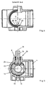
- Fig. 3 shows the housing 1 in a view from above and Fig. 4 in a Section along the line A-A in Fig. 3. From these two figures is a recess 18 trained guide visible, which is the inclusion of the guide element serves and forms together with this a lower bearing point for the ball.
- This recess 18 is formed of three integral with the housing 1 Jetties 19, 20 limited.
- the central web 19 has a concave end face 19A, whose radius corresponds to the radius of the bearing element of the ball.
- the housing 1 is formed in the present case so that the ball can be introduced into the housing 1 via the third fluid opening 4.
- the recess 18 has an opening 22 which is aligned with the third fluid opening 4.
- the insertion of the ball 10 into the housing 1 will be explained in more detail with reference to FIG become.
- a pin 24th introduced from the inside of the housing in the bore 8.
- the pin 24 has a serving as a stop collar end portion 25, in the form of the recess 13 on the top of the ball 10 corresponds.
- the ball 10 is inserted through the third fluid port 4 in the housing 1 and the specialistsslement 16 are introduced via the opening in the recess 18.
- the end portion 25 of the pin 24 received in the recess 13 of the ball 1 can be, the ball 1 is slightly tilted when inserted into the housing 1, which indicated by a drawn by broken lines ball 10A is.
- the supported in the bore 8 of the housing 1 pin 24 thus forms an upper bearing 26.
- the axis of rotation of the ball 10 is denoted by the reference numeral 28 provided.
- the two bearings 26, 27 are diametrically opposed to each other Sides of the ball 10 are arranged.
- an actuating lever (not shown) is provided, the end of the Pin 24 is attached.
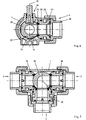
- Fig. 6 shows a cross section through the assembled ball valve.
- a hollow cylindrical design Screw member 30 is provided, which is provided with an external thread 31.
- This screw-in 30 is on the front end with a ball seal 33rd provided, by means of which the ball 10 relative to the housing 1 and the fluid openings is sealed.
- the screw 30 is with a predetermined force tightened, so that the ball seal 33 fits snugly against the ball 10.
- the screw 30 is in the third Screwed fluid port 4, causing the bearing element 16 of the ball 10 at the central, the recess rearwardly limiting web 19 applies and the Ball 10 fixed in the recess.
- the ball could also spring elements be fixed in the housing.
- the bearing element could be in Direction of the axis of rotation 28 are resiliently supported on the ball.
- the recess forward by a resilient web is limited. In both cases, the ball would be after insertion into the housing fixed, so that the Einschraubetti only take over the actual sealing function would.
- FIG. 7 The fully assembled ball valve is shown in FIG. 7 in a horizontal Longitudinal section visible. In this illustration is one of five possible Kirstelllitch the ball 10 is located. In addition, it can be seen that in all three fluid ports 2, 3, 4 each a screw-30 is received.
Landscapes
- Engineering & Computer Science (AREA)
- General Engineering & Computer Science (AREA)
- Mechanical Engineering (AREA)
- Taps Or Cocks (AREA)
- Valve Housings (AREA)
- Fuel-Injection Apparatus (AREA)
- External Artificial Organs (AREA)
- Temperature-Responsive Valves (AREA)
Description
Claims (11)
- Dreiwegekugelhahn, mit einem einstückig ausgebildeten T-förmigen Gehäuse (1), wobei das Gehäuse (1) drei Fluidöffnungen (2, 3, 4) aufweist, wobei zwei Fluidöffnungen (2, 3) koaxial zueinander und die dritte Fluidöffnung (4) im rechten Winkel dazu angeordnet ist und mit einer drehbar darin aufgenommenen Kugel (10), wobei die Kugel (10) und das Gehäuse (1) derart aufeinander abgestimmt sind, dass die Kugel (10) durch die dritte Fluidöffnung (4) von aussen in das Gehäuse (1) einsetzbar ist, wobei die Kugel (10) an einer ersten Lagerstelle (26) einseitig im Gehäuse (1) abgestützt ist, und wobei eine weitere, der ersten Lagerstelle (26) diametral gegenüberliegende Lagerstelle (27) zur Abstützung der Kugel (10) vorgesehen ist, wobei die weitere Lagerstelle (27) durch ein Lagerelement (16) und eine korrespondierende Führung (18) gebildet ist, dadurch gekennzeichnet, dass das Lagerelement (16) einstückig an der Kugel (10) ausgebildet ist und die Führung (18) am Gehäuse (1) ausgebildet ist, dass die Kugel (10) auf der Unterseite mit einer Abflachung (15) versehen ist, aus welcher das Lagerelement (16) vorsteht, dass eine zum Einführen des Lagerelements (16) in die Führung (18) vorgesehene Öffnung (22) mit der dritten Fluidöffnung (4) fluchtend ausgebildet ist, und dass ferner in sämtlichen Fluidöffnungen (2, 3, 4) je ein Mittel (30) zum Fixieren der in das Gehäuse (1) eingesetzten Kugel (10) vorgesehen sind.
- Dreiwegekugelhahn nach Anspruch 1, dadurch gekennzeichnet, dass die Führung als Aussparung (18) ausgebildet ist und eine Öffnung (22) aufweist, über welche das Lagerelement (16) in die Aussparung (18) einführbar ist.
- Dreiwegekugelhahn nach zumindest einem der Ansprüche 1 oder 2, dadurch gekennzeichnet, dass die zur Aufnahme des Lagerelements (16) vorgesehene Führung (18) zumindest teilweise durch ein federndes Element begrenzt ist,
- Dreiwegekugelhahn nach zumindest einem der Ansprüche 1 bis 3, dadurch gekennzeichnet, dass das Lagerelement (16) in Richtung der Drehachse (28) der Kugel (10) federnd abgestützt ist,
- Dreiwegekugelhahn nach zumindest einem der vorhergehenden Ansprüche, dadurch gekennzeichnet, dass die Kugel (10) mit einer Ausnehmung (13) versehen ist, in welche ein als Lagerbolzen für die ersten Lagerstelle (26) dienender Zapfen (24) einführbar ist.
- Dreiwegekugelhahn nach zumindest einem der vorhergehenden Ansprüche, dadurch gekennzeichnet, dass das Gehäuse (1) eine Bohrung (8) zur Aufnahme des Zapfens (24) aufweist, wobei der Zapfen (24) einen Fortsatz (25) aufweist, dessen Form mit der Ausnehmung (13) der Kugel (10) korrespondiert, und wobei der Zapfen (24) von der Innenseite des Gehäuses (1) her in diese Bohrung (8) einsetzbar ist und der Fortsatz (25) den Zapfen (24) beim Einsetzen der Kugel (10) in das Gehäuse (1) in die Ausnehmung (13) einführbar ist.
- Dreiwegekugelhahn nach Anspruch 6, dadurch gekennzeichnet, dass der Fortsatz (25), zum form- und kraftschlüssigen Verbinden des Zapfens (24) mit der Kugel (10), im wesentlichen rechteckig ausgebildet ist.
- Dreiwegekugelhahn nach zumindest einem der vorhergehenden Ansprüche, dadurch gekennzeichnet, dass die Kugel (10) auf der Oberseite mit einer Abflachung (12) versehen ist, in welche die zur Aufnahme des Zapfens (24) vorgesehene Ausnehmung (13) eingelassen ist.
- Dreiwegekugelhahn nach zumindest einem der vorhergehenden Ansprüche, dadurch gekennzeichnet, dass die Fluidöffnungen (2, 3, 4) des Gehäuses (1) mit je einem Innengewinde (5) versehen sind, und dass in die Innengewinde (5) einschraubbare Einschraubelemente (30) vorgesehen sind, welche als Mittel zum Fixieren der in das Gehäuse (1) eingesetzten Kugel (10) vorgesehen sind.
- Dreiwegekugelhahn nach Anspruch 9, dadurch gekennzeichnet, dass zwischen dem Einschraubelement (30) und der Kugel (10) jeweils eine Dichtung (33) angeordnet ist.
- Dreiwegekugelhahn nach einem der Ansprüche 5 bis 8, dadurch gekennzeichnet, dass der Zapfen (24) am Ende mit einem Betätigungshebel versehen ist.
Applications Claiming Priority (2)
| Application Number | Priority Date | Filing Date | Title |
|---|---|---|---|
| DE19846084A DE19846084C2 (de) | 1998-10-07 | 1998-10-07 | Kugelhahn |
| DE19846084 | 1998-10-07 |
Publications (3)
| Publication Number | Publication Date |
|---|---|
| EP0992724A2 EP0992724A2 (de) | 2000-04-12 |
| EP0992724A3 EP0992724A3 (de) | 2001-07-25 |
| EP0992724B1 true EP0992724B1 (de) | 2003-11-05 |
Family
ID=7883622
Family Applications (1)
| Application Number | Title | Priority Date | Filing Date |
|---|---|---|---|
| EP99117114A Expired - Lifetime EP0992724B1 (de) | 1998-10-07 | 1999-08-31 | Kugelhahn |
Country Status (4)
| Country | Link |
|---|---|
| US (1) | US6253791B1 (de) |
| EP (1) | EP0992724B1 (de) |
| AT (1) | ATE253702T1 (de) |
| DE (2) | DE19846084C2 (de) |
Families Citing this family (18)
| Publication number | Priority date | Publication date | Assignee | Title |
|---|---|---|---|---|
| US6736365B2 (en) | 1999-06-24 | 2004-05-18 | Naams, Llc | Valve for use in producing cast concrete articles |
| CA95814S (en) | 1999-12-17 | 2002-05-31 | Hydraulic Eng S A | Ball for ball valves |
| US6578511B1 (en) | 2000-10-20 | 2003-06-17 | James T. Dexter | Pneumatic signaling device for divers |
| US20050156130A1 (en) * | 2003-02-13 | 2005-07-21 | Gigit Incorporated | Shunt valve for use in winterizing a pool |
| US6935368B1 (en) * | 2003-05-27 | 2005-08-30 | Jen-Chieh Lee | Cold-hot water faucet |
| ITBS20030109A1 (it) * | 2003-10-31 | 2005-05-01 | Siral S P A | Valvola a sfera regolatrice e miscelatrice. |
| US7878237B2 (en) * | 2004-03-19 | 2011-02-01 | Tesco Corporation | Actuation system for an oilfield tubular handling system |
| US7083158B1 (en) | 2004-05-17 | 2006-08-01 | Burt James E | Remote operable corporation stop for water supply sources |
| US20060037655A1 (en) * | 2004-08-17 | 2006-02-23 | Ferrer Beltran Jose M | Three-way valve with independent quarter-turn outlets |
| US20070068584A1 (en) * | 2005-09-27 | 2007-03-29 | Murdock Douglas J | Y-manifold valve |
| EP2195585A1 (de) * | 2007-10-03 | 2010-06-16 | Dux Manufacturing Limited | Sonnenenergie-heisswasseranlage und verfahren zum betrieb einer sonnenenergie-heisswasseranlage |
| US9010413B2 (en) | 2012-12-19 | 2015-04-21 | Oil States Energy Services, L.L.C. | Ball drop wellhead control apparatus |
| US9260933B2 (en) | 2013-01-15 | 2016-02-16 | Oil States Energy Services, L.L.C. | Modular ball drop |
| DK3037699T3 (en) | 2014-12-22 | 2018-11-19 | Grundfos Holding As | Mixer |
| US10471286B2 (en) * | 2015-11-24 | 2019-11-12 | Purdue Research Foundation | Systems and methods for improving efficiency of firefighting robots |
| US11306856B2 (en) * | 2017-03-02 | 2022-04-19 | The Harrington Corporation | Connection system for push joint valve and fittings |
| USD844750S1 (en) * | 2017-04-20 | 2019-04-02 | Sloan Valve Company | Three port valve |
| JP1657925S (de) * | 2019-09-27 | 2020-04-20 |
Family Cites Families (15)
| Publication number | Priority date | Publication date | Assignee | Title |
|---|---|---|---|---|
| US2734715A (en) * | 1956-02-14 | Spherical valve | ||
| US3016062A (en) * | 1961-01-03 | 1962-01-09 | Kaiser Ind Corp | Rotary ball valve |
| US3112758A (en) * | 1961-01-06 | 1963-12-03 | Weatherhead Co | Ball valve |
| US3206164A (en) * | 1962-10-31 | 1965-09-14 | Acf Ind Inc | Internally trunnioned valve member |
| FR2202572A5 (de) * | 1972-10-09 | 1974-05-03 | Cailhoux Victor | |
| JPS51143927A (en) * | 1975-06-06 | 1976-12-10 | Kitazawa Shoji Kk | Ball valve |
| US4103868A (en) * | 1976-12-29 | 1978-08-01 | Elkhart Brass Manufacturing Co., Inc. | Ball valve having an improved ball element design |
| US4206904A (en) * | 1978-01-13 | 1980-06-10 | Nyson Group Marketing, Ltd. | Ball valve |
| US4262691A (en) * | 1979-06-29 | 1981-04-21 | Acf Industries, Incorporated | Cam means for ball valve seat rings |
| US4572239A (en) * | 1981-08-28 | 1986-02-25 | Whitey Co. | High pressure ball valve |
| US4467823A (en) * | 1981-11-04 | 1984-08-28 | Shafco Industries Inc. | High pressure ball valve |
| JPS5913170A (ja) * | 1982-07-14 | 1984-01-23 | Tlv Co Ltd | 多方向ボ−ル弁 |
| US4637421A (en) * | 1986-05-15 | 1987-01-20 | Stunkard Gerald A | In-line repairable top entry ball valve |
| DE4436202A1 (de) * | 1994-09-29 | 1996-04-11 | Rautenkranz Int Hermann | Kellyhahn mit doppelt gelagertem Kugelküken |
| DE29805106U1 (de) * | 1998-03-20 | 1998-08-20 | Armaturen & Automatisierungs GmbH Fritz Wehlan, 19273 Neuhaus | Spezial-Kompakt-Kugelhahn mit einem losen, eingelegten Dichtring zur Kugel an einer Seite im Gehäuse |
-
1998
- 1998-10-07 DE DE19846084A patent/DE19846084C2/de not_active Expired - Fee Related
-
1999
- 1999-08-31 DE DE59907615T patent/DE59907615D1/de not_active Expired - Lifetime
- 1999-08-31 EP EP99117114A patent/EP0992724B1/de not_active Expired - Lifetime
- 1999-08-31 AT AT99117114T patent/ATE253702T1/de active
- 1999-10-07 US US09/411,675 patent/US6253791B1/en not_active Expired - Lifetime
Also Published As
| Publication number | Publication date |
|---|---|
| EP0992724A3 (de) | 2001-07-25 |
| US6253791B1 (en) | 2001-07-03 |
| ATE253702T1 (de) | 2003-11-15 |
| EP0992724A2 (de) | 2000-04-12 |
| DE59907615D1 (de) | 2003-12-11 |
| DE19846084A1 (de) | 2000-04-27 |
| DE19846084C2 (de) | 2003-04-30 |
Similar Documents
| Publication | Publication Date | Title |
|---|---|---|
| DE19846084C2 (de) | Kugelhahn | |
| DE20104878U1 (de) | Bidirektionales Kugelventil | |
| EP0757742B1 (de) | Selbsttätiger türschliesser und verfahren zur montage desselben | |
| EP1911925B1 (de) | Rahmen für Fenster, Türen, Fassadenelemente und dergleichen | |
| DE3447797A1 (de) | Einrichtung zum regeln der foerdermenge von rotationsverdichtern | |
| EP4384749B1 (de) | Ventil für eine gaskartusche, gaskartusche für einen wassersprudler und verfahren zum befüllen einer solchen gaskartusche | |
| DE69103982T2 (de) | Zweistufiges Reduzierventil, insbesondere für Gasflaschen. | |
| DE3001538C2 (de) | Entlüftungsvorrichtung für ein Ventil | |
| CH660410A5 (de) | Mehrwege-hahn. | |
| DE867190C (de) | Sicherheitsventil | |
| DE10342103B4 (de) | Absperrventil für einen ortsbeweglichen Druckgasbehälter, insbesondere für eine Pressluftflasche für den Taucheinsatz | |
| DE10061441B4 (de) | Ventil, insbesondere Heizkörperventil | |
| EP1527295B1 (de) | Drei-wege-kugelhahn | |
| DE4211551A1 (de) | Verstellpumpe mit einem Druckbegrenzungs- und einem Druckzuschaltventil | |
| DE29618605U1 (de) | Absperrarmatur | |
| EP1182386B1 (de) | Absperrvorrichtung mit Dichtung | |
| DE2636965C3 (de) | Anbohrvorrichtung für ein unter Druck stehendes Rohr | |
| DE19504296C1 (de) | Luftfederventil mit Feineinstellung | |
| WO2001004497A1 (de) | Vorgesteuertes schieberventil | |
| DE2213844C3 (de) | Kükensicherung für einen Haha | |
| DE2332151A1 (de) | Kugelhahn | |
| DE19534021B4 (de) | Für einen Kraftstoffbehälter ausgebildeter Verschlußdeckel | |
| DE4206237C1 (en) | Stop fitting with valve plug in housing - has valve plug abutting in stop position elastic sealing sleeve with straight sealing faces | |
| EP0716255A1 (de) | Sanitärarmatur | |
| EP1384924B1 (de) | Plättchen-Rückschlagventil |
Legal Events
| Date | Code | Title | Description |
|---|---|---|---|
| PUAI | Public reference made under article 153(3) epc to a published international application that has entered the european phase |
Free format text: ORIGINAL CODE: 0009012 |
|
| AK | Designated contracting states |
Kind code of ref document: A2 Designated state(s): AT BE CH CY DE DK ES FI FR GB GR IE IT LI LU MC NL PT SE |
|
| AX | Request for extension of the european patent |
Free format text: AL;LT;LV;MK;RO;SI |
|
| PUAL | Search report despatched |
Free format text: ORIGINAL CODE: 0009013 |
|
| AK | Designated contracting states |
Kind code of ref document: A3 Designated state(s): AT BE CH CY DE DK ES FI FR GB GR IE IT LI LU MC NL PT SE |
|
| AX | Request for extension of the european patent |
Free format text: AL;LT;LV;MK;RO;SI |
|
| 17P | Request for examination filed |
Effective date: 20011208 |
|
| AKX | Designation fees paid |
Free format text: AT BE CH CY DE DK ES FI FR GB GR IE IT LI LU MC NL PT SE |
|
| 17Q | First examination report despatched |
Effective date: 20020725 |
|
| GRAH | Despatch of communication of intention to grant a patent |
Free format text: ORIGINAL CODE: EPIDOS IGRA |
|
| GRAS | Grant fee paid |
Free format text: ORIGINAL CODE: EPIDOSNIGR3 |
|
| GRAA | (expected) grant |
Free format text: ORIGINAL CODE: 0009210 |
|
| AK | Designated contracting states |
Kind code of ref document: B1 Designated state(s): AT BE CH CY DE DK ES FI FR GB GR IE IT LI LU MC NL PT SE |
|
| PG25 | Lapsed in a contracting state [announced via postgrant information from national office to epo] |
Ref country code: NL Free format text: LAPSE BECAUSE OF FAILURE TO SUBMIT A TRANSLATION OF THE DESCRIPTION OR TO PAY THE FEE WITHIN THE PRESCRIBED TIME-LIMIT Effective date: 20031105 Ref country code: IE Free format text: LAPSE BECAUSE OF FAILURE TO SUBMIT A TRANSLATION OF THE DESCRIPTION OR TO PAY THE FEE WITHIN THE PRESCRIBED TIME-LIMIT Effective date: 20031105 Ref country code: GB Free format text: LAPSE BECAUSE OF FAILURE TO SUBMIT A TRANSLATION OF THE DESCRIPTION OR TO PAY THE FEE WITHIN THE PRESCRIBED TIME-LIMIT Effective date: 20031105 Ref country code: FR Free format text: LAPSE BECAUSE OF FAILURE TO SUBMIT A TRANSLATION OF THE DESCRIPTION OR TO PAY THE FEE WITHIN THE PRESCRIBED TIME-LIMIT Effective date: 20031105 Ref country code: FI Free format text: LAPSE BECAUSE OF FAILURE TO SUBMIT A TRANSLATION OF THE DESCRIPTION OR TO PAY THE FEE WITHIN THE PRESCRIBED TIME-LIMIT Effective date: 20031105 Ref country code: ES Free format text: LAPSE BECAUSE OF FAILURE TO SUBMIT A TRANSLATION OF THE DESCRIPTION OR TO PAY THE FEE WITHIN THE PRESCRIBED TIME-LIMIT Effective date: 20031105 Ref country code: CY Free format text: LAPSE BECAUSE OF FAILURE TO SUBMIT A TRANSLATION OF THE DESCRIPTION OR TO PAY THE FEE WITHIN THE PRESCRIBED TIME-LIMIT Effective date: 20031105 |
|
| REG | Reference to a national code |
Ref country code: GB Ref legal event code: FG4D Free format text: NOT ENGLISH |
|
| REG | Reference to a national code |
Ref country code: CH Ref legal event code: EP |
|
| REF | Corresponds to: |
Ref document number: 59907615 Country of ref document: DE Date of ref document: 20031211 Kind code of ref document: P |
|
| REG | Reference to a national code |
Ref country code: IE Ref legal event code: FG4D Free format text: GERMAN |
|
| PG25 | Lapsed in a contracting state [announced via postgrant information from national office to epo] |
Ref country code: SE Free format text: LAPSE BECAUSE OF FAILURE TO SUBMIT A TRANSLATION OF THE DESCRIPTION OR TO PAY THE FEE WITHIN THE PRESCRIBED TIME-LIMIT Effective date: 20040205 Ref country code: GR Free format text: LAPSE BECAUSE OF FAILURE TO SUBMIT A TRANSLATION OF THE DESCRIPTION OR TO PAY THE FEE WITHIN THE PRESCRIBED TIME-LIMIT Effective date: 20040205 Ref country code: DK Free format text: LAPSE BECAUSE OF FAILURE TO SUBMIT A TRANSLATION OF THE DESCRIPTION OR TO PAY THE FEE WITHIN THE PRESCRIBED TIME-LIMIT Effective date: 20040205 |
|
| NLV1 | Nl: lapsed or annulled due to failure to fulfill the requirements of art. 29p and 29m of the patents act | ||
| GBV | Gb: ep patent (uk) treated as always having been void in accordance with gb section 77(7)/1977 [no translation filed] |
Effective date: 20031105 |
|
| REG | Reference to a national code |
Ref country code: IE Ref legal event code: FD4D |
|
| PG25 | Lapsed in a contracting state [announced via postgrant information from national office to epo] |
Ref country code: MC Free format text: LAPSE BECAUSE OF NON-PAYMENT OF DUE FEES Effective date: 20040831 Ref country code: LU Free format text: LAPSE BECAUSE OF NON-PAYMENT OF DUE FEES Effective date: 20040831 Ref country code: LI Free format text: LAPSE BECAUSE OF NON-PAYMENT OF DUE FEES Effective date: 20040831 Ref country code: CH Free format text: LAPSE BECAUSE OF NON-PAYMENT OF DUE FEES Effective date: 20040831 Ref country code: BE Free format text: LAPSE BECAUSE OF NON-PAYMENT OF DUE FEES Effective date: 20040831 |
|
| PLBE | No opposition filed within time limit |
Free format text: ORIGINAL CODE: 0009261 |
|
| STAA | Information on the status of an ep patent application or granted ep patent |
Free format text: STATUS: NO OPPOSITION FILED WITHIN TIME LIMIT |
|
| 26N | No opposition filed |
Effective date: 20040806 |
|
| EN | Fr: translation not filed | ||
| BERE | Be: lapsed |
Owner name: GEORG *FISCHER ROHRLEITUNGSSYSTEME A.G. Effective date: 20040831 |
|
| REG | Reference to a national code |
Ref country code: CH Ref legal event code: PL |
|
| BERE | Be: lapsed |
Owner name: GEORG *FISCHER ROHRLEITUNGSSYSTEME A.G. Effective date: 20040831 |
|
| PG25 | Lapsed in a contracting state [announced via postgrant information from national office to epo] |
Ref country code: PT Free format text: LAPSE BECAUSE OF NON-PAYMENT OF DUE FEES Effective date: 20040405 |
|
| PGFP | Annual fee paid to national office [announced via postgrant information from national office to epo] |
Ref country code: AT Payment date: 20140619 Year of fee payment: 16 |
|
| PGFP | Annual fee paid to national office [announced via postgrant information from national office to epo] |
Ref country code: IT Payment date: 20140829 Year of fee payment: 16 |
|
| REG | Reference to a national code |
Ref country code: AT Ref legal event code: MM01 Ref document number: 253702 Country of ref document: AT Kind code of ref document: T Effective date: 20150831 |
|
| PG25 | Lapsed in a contracting state [announced via postgrant information from national office to epo] |
Ref country code: IT Free format text: LAPSE BECAUSE OF NON-PAYMENT OF DUE FEES Effective date: 20150831 |
|
| PG25 | Lapsed in a contracting state [announced via postgrant information from national office to epo] |
Ref country code: AT Free format text: LAPSE BECAUSE OF NON-PAYMENT OF DUE FEES Effective date: 20150831 |
|
| PGFP | Annual fee paid to national office [announced via postgrant information from national office to epo] |
Ref country code: DE Payment date: 20180823 Year of fee payment: 20 |
|
| REG | Reference to a national code |
Ref country code: DE Ref legal event code: R071 Ref document number: 59907615 Country of ref document: DE |