EP0992655B1 - Kühlkanal für ein thermisch hochbelastetes Bauteil - Google Patents
Kühlkanal für ein thermisch hochbelastetes Bauteil Download PDFInfo
- Publication number
- EP0992655B1 EP0992655B1 EP99810860A EP99810860A EP0992655B1 EP 0992655 B1 EP0992655 B1 EP 0992655B1 EP 99810860 A EP99810860 A EP 99810860A EP 99810860 A EP99810860 A EP 99810860A EP 0992655 B1 EP0992655 B1 EP 0992655B1
- Authority
- EP
- European Patent Office
- Prior art keywords
- local
- cooling passage
- rib
- ribs
- longitudinal direction
- Prior art date
- Legal status (The legal status is an assumption and is not a legal conclusion. Google has not performed a legal analysis and makes no representation as to the accuracy of the status listed.)
- Expired - Lifetime
Links
Images


Classifications
-
- F—MECHANICAL ENGINEERING; LIGHTING; HEATING; WEAPONS; BLASTING
- F01—MACHINES OR ENGINES IN GENERAL; ENGINE PLANTS IN GENERAL; STEAM ENGINES
- F01D—NON-POSITIVE DISPLACEMENT MACHINES OR ENGINES, e.g. STEAM TURBINES
- F01D5/00—Blades; Blade-carrying members; Heating, heat-insulating, cooling or antivibration means on the blades or the members
- F01D5/12—Blades
- F01D5/14—Form or construction
- F01D5/18—Hollow blades, i.e. blades with cooling or heating channels or cavities; Heating, heat-insulating or cooling means on blades
- F01D5/187—Convection cooling
-
- F—MECHANICAL ENGINEERING; LIGHTING; HEATING; WEAPONS; BLASTING
- F02—COMBUSTION ENGINES; HOT-GAS OR COMBUSTION-PRODUCT ENGINE PLANTS
- F02C—GAS-TURBINE PLANTS; AIR INTAKES FOR JET-PROPULSION PLANTS; CONTROLLING FUEL SUPPLY IN AIR-BREATHING JET-PROPULSION PLANTS
- F02C7/00—Features, components parts, details or accessories, not provided for in, or of interest apart form groups F02C1/00 - F02C6/00; Air intakes for jet-propulsion plants
-
- F—MECHANICAL ENGINEERING; LIGHTING; HEATING; WEAPONS; BLASTING
- F05—INDEXING SCHEMES RELATING TO ENGINES OR PUMPS IN VARIOUS SUBCLASSES OF CLASSES F01-F04
- F05D—INDEXING SCHEME FOR ASPECTS RELATING TO NON-POSITIVE-DISPLACEMENT MACHINES OR ENGINES, GAS-TURBINES OR JET-PROPULSION PLANTS
- F05D2260/00—Function
- F05D2260/20—Heat transfer, e.g. cooling
- F05D2260/221—Improvement of heat transfer
- F05D2260/2212—Improvement of heat transfer by creating turbulence
-
- F—MECHANICAL ENGINEERING; LIGHTING; HEATING; WEAPONS; BLASTING
- F05—INDEXING SCHEMES RELATING TO ENGINES OR PUMPS IN VARIOUS SUBCLASSES OF CLASSES F01-F04
- F05D—INDEXING SCHEME FOR ASPECTS RELATING TO NON-POSITIVE-DISPLACEMENT MACHINES OR ENGINES, GAS-TURBINES OR JET-PROPULSION PLANTS
- F05D2260/00—Function
- F05D2260/20—Heat transfer, e.g. cooling
- F05D2260/221—Improvement of heat transfer
- F05D2260/2214—Improvement of heat transfer by increasing the heat transfer surface
- F05D2260/22141—Improvement of heat transfer by increasing the heat transfer surface using fins or ribs
Definitions
- the invention relates to a cooling channel of a thermally highly stressed component according to the preamble of claim 1.
- the cooling channel arises as a cavity between a suction side and a pressure side Wall connected by a front and a rear edge area are.
- the resulting cavity has a crescent-shaped, orthogonal to the longitudinal direction curved cross-section and extending in the longitudinal direction straight between blade root and blade tip.
- the cavity are arranged alternately on the suction and the pressure side wall cooling fins, which enclose an acute angle with respect to a projected center axis, wherein the center axis arises from an orthogonal projection of a plane, the extends radially to the blade and perpendicular to the insides of the walls and on the widest point of the cavity is arranged.
- the cooling fluid is thus in a kind of wave motion passed through the cooling channel, the special Shape of the ribs ensures good cooling efficiency.
- the invention seeks to avoid the disadvantages described. She is the one Task, a cooling channel of a thermally highly stressed component of specify the type mentioned, which allows the cooling effect even at an orthogonal to the longitudinal direction very strongly curved course of the cavity to further uniform and in this way the need for cooling medium to minimize.
- the ribs are designed so that the ratio of local rib division to a local rib height substantially at each point of the rib is constant. This achieves one in the flow direction of the cooling fluid considers constant heat transfer intensification with the result a not very varying temperature distribution and thus low thermal stresses in the component.
- the cooling fluid preferably in thermally highly loaded edge regions of the cavity to force by secondary currents. Due to the occurring secondary flows becomes the cooling fluid from the edge region with the cooling fluid in the core region mixed, where the externally registered heat load is low.
- the ratio of local rib division to local fin height adjust so that a uniform temperature is maintained in the longitudinal direction of the channel.
- the ratio between local fin height becomes advantageous and local cavity height continuously increased in the flow direction, thereby the temperature distribution in the longitudinal direction even further leaves.
- the ribs each of two form curved rib segments and a tip, causing dead water areas almost completely prevented in the side area. Frequently just in these places the heat input highest, making it special There depends on an intensification of the cooling effect.
- the ribs are designed to be in an orthogonal projection can be represented as an angle with rectilinear legs. This provides for a variety of occurring in practice applications under fluidically optimal to be considered rib shape, the constructive can be produced with reasonable effort.
- angles are particularly preferably symmetrical with respect to the center axis and arranged parallel to each other.
- the cooling concept according to the invention in principle arbitrarydekanalkonfigurationen is applicable, it is particularly suitable for use on a coolable turbine blade or combustion chamber wall of a gas turbine, which are exposed to thermal loads in particular and Moreover, in terms of overall efficiency, the cooling demand on the has considerable influence for ecological and economic reasons constantly needs to be improved.
- Fig. 1 is a cavity 2 of a gas turbine blade not shown in more detail shown. He has a blade root section 12 and goes to at the top into a section passing through a suction-side wall 5 and a pressure-side wall 6 is defined.
- the suction-side wall 5 and the pressure-side Wall 6 each adjoin one another laterally and are in a leading edge area 3 and a trailing edge region 4 connected to each other.
- At the suction side Wall 5 are ribs 7a, 7c and on the pressure-side wall 6 ribs 7b, 7d attached.
- the ribs 7a, 7b, 7c, 7d are alternating in the longitudinal direction L. and offset from one another.
- the ribs 7a, 7b, 7c, 7d as an angle 7a ', 7b', 7c ', 7d' with rectilinear Thighs shown. Tips 9a ', 9b', 9c ', 9d' the angles 7a ', 7b', 7c ', 7d' lie on a central axis 10 '.
- the angles 7a ', 7b', 7c ', 7d' are equidistant and arranged parallel to each other.
- the representation according to FIG. 1 illustrates that the ribs 7 a, 7 b, 7 c, 7 d a have curved contour, which is created by pointwise construction.
- the condition is met for each point that the distance a in relation on the respectively adjacent rib of the opposite wall of the half corresponds to a respective local fin pitch p.
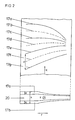
- FIG. 2 a configuration is shown in which the heat transfer intensification is kept constant in the flow direction K.
- a cavity 20 has again ribs 17a, 17b, 17c, 17d, 17e, 17f, 17g, which alternately and to each other offset are attached. Due to the curvature of the cavity 20 is the local fin pitch p in a coordinate direction y varies very much, so that the ribs 17a, 17b, 17c, 17d, 17e, 17f, 17g are also very strongly curved run.
- Ribs 17a, 17b, 17c, 17d, 17e, 17f, 17g require the ratio of local Rib division p to a local rib height e at each point constant hold. This leads to a rib shape, which is very much three-dimensional is shaped.
- a rib 27 has an elevation 28, which by varying the ratio from local rib height e to a local ceiling height h has arisen. As a result, the flow is deflected into the lateral areas and occur On secondary flows. The secondary flows ensure mixing of strongly heated cooling fluid from the edge regions with cooling fluid from the core region, and thus allow temperature compensation.
- the ratio of local fin pitch p to local fin height is now also e each chosen so that a uniform temperature in one Coordinate direction r.
- the ratio of local Rib pitch p to local rib height e in the range between 12 for the side area and FIG. 10 is selected for the core region according to the embodiment of FIG become.
- the result is a very strongly three-dimensionally contoured rib shape, wherein each rib 27a, 27c, 27e is deviated in shape.
Landscapes
- Engineering & Computer Science (AREA)
- Chemical & Material Sciences (AREA)
- Combustion & Propulsion (AREA)
- Mechanical Engineering (AREA)
- General Engineering & Computer Science (AREA)
- Turbine Rotor Nozzle Sealing (AREA)
- Cooling Or The Like Of Electrical Apparatus (AREA)
- Cooling Or The Like Of Semiconductors Or Solid State Devices (AREA)
Description
- Fig. 1
- Kühlkanal einer Turbinenschaufel mit Rippen in perspektivischer Ansicht einschließlich dessen Orthogonalprojektion;
- Fig. 2
- Kühlkanalabschnitt im Teillängsschnitt sowie im Querschnitt, Ausführungsvariante;
- Fig. 3
- Kühlkanalabschnitt im Teillängsschnitt sowie im Querschnitt, weitere Ausführungsvariante;
- 2
- Hohlraum
- 3
- Vorderkantenbereich
- 4
- Hinterkantenbereich
- 5
- saugseitige Wand
- 6
- druckseitige Wand
- 7a, 7c
- Rippe saugseitige Wand
- 7b, 7d
- Rippe druckseitige Wand
- 7a', 7b', 7c', 7d'
- Winkel (projizierte Rippe)
- 8
- Projektionsebene
- 9a, 9b, 9c, 9d
- Rippenspitze
- 9a', 9b', 9c', 9d'
- Spitze (projizierte Spitze)
- 10'
- Mittenachse (projiziert)
- 12
- Schaufelfußabschnitt
- 12'
- Schaufelfußabschnitt (projiziert)
- 20
- Hohlraum
- 17a, 17b, 17c, 17d, 17e, 17f, 17g
- Rippe
- 27, 27a, 27c, 27e
- Rippe
- 28
- Überhöhung
- 30
- Hohlraum
- a
- Abstand
- e
- lokale Rippenhöhe
- h
- lokale Hohlraumhöhe
- p
- lokale Rippenteilung
- r
- Koordinatenrichtung
- y
- Koordinatenrichtung
- K
- Kühlfluid(strömung)
- L
- Längsrichtung
Claims (10)
- Kühlkanal eines thermisch hochbelasteten Bauteils,dadurch gekennzeichnet, dassder als in einer Längsrichtung (L) verlaufender und orthogonal zur Längsrichtung (L) gekrümmter Hohlraum (2, 20, 30) zwischen einer ersten Wand (5) und einer zweiten Wand (6) gebildet ist, welche jeweils seitlich aneinander grenzend miteinander verbunden sind,der Rippen (7, 17, 27) aufweist, die in Längsrichtung (L) abwechselnd und zueinander versetzt an der ersten Wand (5) und zweiten Wand (6) angeordnet sind, und die zumindest abschnittsweise gegenüber einer projizierten Mittenachse (10') einen nicht-orthogonalen Winkel einnehmen, undder von einem Kühlfluid (K) in Längsrichtung (L) durchströmbar ist,die Rippen (7, 17, 27) jeweils aus zwei gekrümmten Rippensegmenten bestehen, die vom gradlinigen Verlauf, der durch den Anfangs- und Endpunkt der Rippensegmente geht, in Längsrichtung (L) des Kühlkanals abweicht, und eine Spitze (9) aufweisen.
- Kühlkanal nach Anspruch 1,
dadurch gekennzeichnet, dass
bei einem orthogonal zur Längsrichtung (L) gekrümmten Verlauf des Hohlraumes (2, 20, 30) die Rippen (7, 17, 27) derart geformt sind, dass sie jeweils lokal in bezug auf die benachbarte Rippe der gegenüberliegenden Wand einen Abstand (a) einhalten, der die Hälfte einer jeweiligen lokalen Rippenteilung (p) beträgt. - Kühlkanal nach Anspruch 2,
dadurch gekennzeichnet, dass
das Verhältnis von lokaler Rippenteilung (p) zu einer lokalen Rippenhöhe (e) im wesentlichen an jedem Punkt der Rippe (7, 17, 27) konstant ist. - Kühlkanal nach Anspruch 1, dadurch gekennzeichnet, dass das Verhältnis von lokaler Rippenhöhe (e) zu einer lokalen Hohlraumhöhe (h) zur Bildung lokaler Überhöhungen (28) variiert.
- Kühlkanal nach Anspruch 2 oder 4, dadurch gekennzeichnet, dass das Verhältnis von lokaler Rippenteilung (p) zu lokaler Rippenhöhe (e) variiert.
- Kühlkanal nach einem der vorstehenden Ansprüche, dadurch gekennzeichnet, dass das Verhältnis von lokaler Rippenhöhe (e) zu lokaler Hohlraumhöhe (h) für nacheinander in Längsrichtung angeordnete Rippen (7, 17, 27) zunimmt.
- Kühlkanal nach Anspruch 1, dadurch gekennzeichnet, dass die Rippen (7) in einer Orthogonalprojektion als Winkel (7') mit geradlinig verlaufenden Schenkeln abbildbar sind.
- Kühlkanal nach Anspruch 7, dadurch gekennzeichnet, dass sämtliche Winkel (7') symmetrisch in Bezug auf eine Mittenachse (10') und parallel zueinander angeordnet sind.
- Kühlkanal nach einem der vorstehenden Ansprüche als Bestandteil einer kühlbaren Turbinenschaufel.
- Kühlkanal nach einem der vorstehenden Ansprüche als Bestandteil einer kühlbaren Brennkammerwandung einer Gasturbine.
Applications Claiming Priority (2)
| Application Number | Priority Date | Filing Date | Title |
|---|---|---|---|
| DE19846332 | 1998-10-08 | ||
| DE19846332A DE19846332A1 (de) | 1998-10-08 | 1998-10-08 | Kühlkanal eines thermisch hochbelasteten Bauteils |
Publications (3)
| Publication Number | Publication Date |
|---|---|
| EP0992655A2 EP0992655A2 (de) | 2000-04-12 |
| EP0992655A3 EP0992655A3 (de) | 2001-12-12 |
| EP0992655B1 true EP0992655B1 (de) | 2004-12-08 |
Family
ID=7883786
Family Applications (1)
| Application Number | Title | Priority Date | Filing Date |
|---|---|---|---|
| EP99810860A Expired - Lifetime EP0992655B1 (de) | 1998-10-08 | 1999-09-24 | Kühlkanal für ein thermisch hochbelastetes Bauteil |
Country Status (3)
| Country | Link |
|---|---|
| US (1) | US6343474B1 (de) |
| EP (1) | EP0992655B1 (de) |
| DE (2) | DE19846332A1 (de) |
Families Citing this family (6)
| Publication number | Priority date | Publication date | Assignee | Title |
|---|---|---|---|---|
| ITMO20020025A1 (it) * | 2002-02-07 | 2003-08-07 | Vittorio Fiorini | Mezzi generatori di energia |
| GB0222352D0 (en) * | 2002-09-26 | 2002-11-06 | Dorling Kevin | Turbine blade turbulator cooling design |
| US9334755B2 (en) * | 2012-09-28 | 2016-05-10 | United Technologies Corporation | Airfoil with variable trip strip height |
| WO2014159589A1 (en) * | 2013-03-14 | 2014-10-02 | United Technologies Corporation | Gas turbine engine component cooling with interleaved facing trip strips |
| EP2832956A1 (de) * | 2013-07-29 | 2015-02-04 | Siemens Aktiengesellschaft | Turbinenschaufel mit tragflächenprofilförmigen Kühlkörpern |
| US10927682B2 (en) | 2017-11-16 | 2021-02-23 | General Electric Company | Engine component with non-diffusing section |
Family Cites Families (12)
| Publication number | Priority date | Publication date | Assignee | Title |
|---|---|---|---|---|
| GB1410014A (en) | 1971-12-14 | 1975-10-15 | Rolls Royce | Gas turbine engine blade |
| US4514144A (en) | 1983-06-20 | 1985-04-30 | General Electric Company | Angled turbulence promoter |
| US5232343A (en) | 1984-05-24 | 1993-08-03 | General Electric Company | Turbine blade |
| GB2159585B (en) * | 1984-05-24 | 1989-02-08 | Gen Electric | Turbine blade |
| JP3006174B2 (ja) * | 1991-07-04 | 2000-02-07 | 株式会社日立製作所 | 内部に冷却通路を有する部材 |
| US5695320A (en) | 1991-12-17 | 1997-12-09 | General Electric Company | Turbine blade having auxiliary turbulators |
| US5695321A (en) * | 1991-12-17 | 1997-12-09 | General Electric Company | Turbine blade having variable configuration turbulators |
| US5700132A (en) | 1991-12-17 | 1997-12-23 | General Electric Company | Turbine blade having opposing wall turbulators |
| US5681144A (en) * | 1991-12-17 | 1997-10-28 | General Electric Company | Turbine blade having offset turbulators |
| DE19634238A1 (de) * | 1996-08-23 | 1998-02-26 | Asea Brown Boveri | Kühlbare Schaufel |
| US5738493A (en) | 1997-01-03 | 1998-04-14 | General Electric Company | Turbulator configuration for cooling passages of an airfoil in a gas turbine engine |
| US5752801A (en) * | 1997-02-20 | 1998-05-19 | Westinghouse Electric Corporation | Apparatus for cooling a gas turbine airfoil and method of making same |
-
1998
- 1998-10-08 DE DE19846332A patent/DE19846332A1/de not_active Withdrawn
-
1999
- 1999-09-23 US US09/401,309 patent/US6343474B1/en not_active Expired - Lifetime
- 1999-09-24 EP EP99810860A patent/EP0992655B1/de not_active Expired - Lifetime
- 1999-09-24 DE DE1999511226 patent/DE59911226D1/de not_active Expired - Lifetime
Also Published As
| Publication number | Publication date |
|---|---|
| US6343474B1 (en) | 2002-02-05 |
| EP0992655A3 (de) | 2001-12-12 |
| DE59911226D1 (de) | 2005-01-13 |
| EP0992655A2 (de) | 2000-04-12 |
| DE19846332A1 (de) | 2000-04-13 |
Similar Documents
| Publication | Publication Date | Title |
|---|---|---|
| DE102014119701B4 (de) | Strukturelle Ausbildung (einer Turbinenschaufel) und Kühlung (derselben) | |
| DE60017437T2 (de) | Rippen zur erhöhung der wärmeübertragung einer mittels kühlluft innengekühlten turbinenschaufel | |
| DE69216501T2 (de) | Turbinenschaufel mit Innenkühlungskanal | |
| EP1267039B1 (de) | Kühlkonstruktion für Schaufelblatthinterkante | |
| EP3762587B1 (de) | Schaufelblatt für eine turbinenschaufel | |
| DE102014119693B4 (de) | Turbinenschaufel mit hohlem schaufelblatt mit inneren rippen und kühlkanälen | |
| CH709094A2 (de) | Turbinenschaufel mit einer Kammer zur Aufnahme eines Kühlmittelstroms. | |
| EP1113145A1 (de) | Schaufel für Gasturbinen mit Drosselquerschnitt an Hinterkante | |
| EP0825332B1 (de) | Kühlbare Schaufel | |
| EP0892149B1 (de) | Kühlsystem für den Vorderkantenbereich einer hohlen Gasturbinenschaufel | |
| DE3518314A1 (de) | Turbinenschaufel | |
| DE102014119418B4 (de) | Strukturelle Anordnungen und Kühlkreise in Turbinenschaufeln | |
| DE102014119423B4 (de) | Innenkühlkreise in Turbinenschaufeln | |
| DE102017110051A1 (de) | Schaufel mit belastungsreduzierendem bauchigem Vorsprung an einer Wendeöffnung von Kühlmittelkanälen | |
| CH709096A2 (de) | Turbinenschaufel mit einer Kammer zur Aufnahme eines Kühlmittelstroms. | |
| EP1192333A1 (de) | Heissgasbeaufschlagbares bauteil, insbesondere turbinenschaufel | |
| EP0992655A2 (de) | Kühlkanal für ein thermisch hochbelastetes Bauteil | |
| EP1118831B1 (de) | Mit Rippenzug versehene Wärmetauscherwand | |
| CH709090A2 (de) | Turbinenschaufel mit einer Kammer zur Aufnahme eines Kühlmittelstroms. | |
| EP2933435A1 (de) | Turbinenschaufel und zugehörige Turbine | |
| DE102019109023B3 (de) | Verdichterlaufrad mit wechselnder Beschaufelung | |
| EP0825333B1 (de) | Kühlbare Turbinenschaufel | |
| EP1016773A2 (de) | Kühlbare Schaufel für eine Gasturbine | |
| WO2013076109A1 (de) | Kühlbares heissgasbauteil für eine gasturbine | |
| DE60208977T2 (de) | Gasturbinenleitschaufel |
Legal Events
| Date | Code | Title | Description |
|---|---|---|---|
| PUAI | Public reference made under article 153(3) epc to a published international application that has entered the european phase |
Free format text: ORIGINAL CODE: 0009012 |
|
| AK | Designated contracting states |
Kind code of ref document: A2 Designated state(s): AT BE CH CY DE DK ES FI FR GB GR IE IT LI LU MC NL PT SE Kind code of ref document: A2 Designated state(s): DE GB |
|
| AX | Request for extension of the european patent |
Free format text: AL;LT;LV;MK;RO;SI |
|
| PUAL | Search report despatched |
Free format text: ORIGINAL CODE: 0009013 |
|
| AK | Designated contracting states |
Kind code of ref document: A3 Designated state(s): AT BE CH CY DE DK ES FI FR GB GR IE IT LI LU MC NL PT SE |
|
| AX | Request for extension of the european patent |
Free format text: AL;LT;LV;MK;RO;SI |
|
| RAP1 | Party data changed (applicant data changed or rights of an application transferred) |
Owner name: ALSTOM |
|
| 17P | Request for examination filed |
Effective date: 20020508 |
|
| AKX | Designation fees paid |
Free format text: DE GB |
|
| RAP1 | Party data changed (applicant data changed or rights of an application transferred) |
Owner name: ALSTOM (SWITZERLAND) LTD |
|
| 17Q | First examination report despatched |
Effective date: 20021111 |
|
| RAP1 | Party data changed (applicant data changed or rights of an application transferred) |
Owner name: ALSTOM TECHNOLOGY LTD |
|
| GRAP | Despatch of communication of intention to grant a patent |
Free format text: ORIGINAL CODE: EPIDOSNIGR1 |
|
| GRAS | Grant fee paid |
Free format text: ORIGINAL CODE: EPIDOSNIGR3 |
|
| GRAA | (expected) grant |
Free format text: ORIGINAL CODE: 0009210 |
|
| AK | Designated contracting states |
Kind code of ref document: B1 Designated state(s): DE GB |
|
| REG | Reference to a national code |
Ref country code: GB Ref legal event code: FG4D Free format text: NOT ENGLISH |
|
| REG | Reference to a national code |
Ref country code: IE Ref legal event code: FG4D Free format text: GERMAN |
|
| REF | Corresponds to: |
Ref document number: 59911226 Country of ref document: DE Date of ref document: 20050113 Kind code of ref document: P |
|
| GBT | Gb: translation of ep patent filed (gb section 77(6)(a)/1977) |
Effective date: 20050223 |
|
| PLBE | No opposition filed within time limit |
Free format text: ORIGINAL CODE: 0009261 |
|
| STAA | Information on the status of an ep patent application or granted ep patent |
Free format text: STATUS: NO OPPOSITION FILED WITHIN TIME LIMIT |
|
| 26N | No opposition filed |
Effective date: 20050909 |
|
| REG | Reference to a national code |
Ref country code: DE Ref legal event code: R082 Ref document number: 59911226 Country of ref document: DE Representative=s name: ROESLER, UWE, DIPL.-PHYS.UNIV., DE Ref country code: DE Ref legal event code: R081 Ref document number: 59911226 Country of ref document: DE Owner name: ANSALDO ENERGIA IP UK LIMITED, GB Free format text: FORMER OWNER: ALSTOM TECHNOLOGY LTD., BADEN, CH Ref country code: DE Ref legal event code: R081 Ref document number: 59911226 Country of ref document: DE Owner name: GENERAL ELECTRIC TECHNOLOGY GMBH, CH Free format text: FORMER OWNER: ALSTOM TECHNOLOGY LTD., BADEN, CH |
|
| REG | Reference to a national code |
Ref country code: DE Ref legal event code: R082 Ref document number: 59911226 Country of ref document: DE Representative=s name: ROESLER, UWE, DIPL.-PHYS.UNIV., DE Ref country code: DE Ref legal event code: R081 Ref document number: 59911226 Country of ref document: DE Owner name: ANSALDO ENERGIA IP UK LIMITED, GB Free format text: FORMER OWNER: GENERAL ELECTRIC TECHNOLOGY GMBH, BADEN, CH |
|
| PGFP | Annual fee paid to national office [announced via postgrant information from national office to epo] |
Ref country code: DE Payment date: 20170928 Year of fee payment: 19 Ref country code: GB Payment date: 20170921 Year of fee payment: 19 |
|
| REG | Reference to a national code |
Ref country code: GB Ref legal event code: 732E Free format text: REGISTERED BETWEEN 20171026 AND 20171101 |
|
| REG | Reference to a national code |
Ref country code: DE Ref legal event code: R119 Ref document number: 59911226 Country of ref document: DE |
|
| GBPC | Gb: european patent ceased through non-payment of renewal fee |
Effective date: 20180924 |
|
| PG25 | Lapsed in a contracting state [announced via postgrant information from national office to epo] |
Ref country code: DE Free format text: LAPSE BECAUSE OF NON-PAYMENT OF DUE FEES Effective date: 20190402 |
|
| PG25 | Lapsed in a contracting state [announced via postgrant information from national office to epo] |
Ref country code: GB Free format text: LAPSE BECAUSE OF NON-PAYMENT OF DUE FEES Effective date: 20180924 |