EP0991110B1 - Halbleiter-Montageeinrichtung mit einem Chipgreifer - Google Patents
Halbleiter-Montageeinrichtung mit einem Chipgreifer Download PDFInfo
- Publication number
- EP0991110B1 EP0991110B1 EP98810988A EP98810988A EP0991110B1 EP 0991110 B1 EP0991110 B1 EP 0991110B1 EP 98810988 A EP98810988 A EP 98810988A EP 98810988 A EP98810988 A EP 98810988A EP 0991110 B1 EP0991110 B1 EP 0991110B1
- Authority
- EP
- European Patent Office
- Prior art keywords
- magnets
- stator
- drive device
- vertical direction
- carriage
- Prior art date
- Legal status (The legal status is an assumption and is not a legal conclusion. Google has not performed a legal analysis and makes no representation as to the accuracy of the status listed.)
- Expired - Lifetime
Links
Images

Classifications
-
- H—ELECTRICITY
- H10—SEMICONDUCTOR DEVICES; ELECTRIC SOLID-STATE DEVICES NOT OTHERWISE PROVIDED FOR
- H10P—GENERIC PROCESSES OR APPARATUS FOR THE MANUFACTURE OR TREATMENT OF DEVICES COVERED BY CLASS H10
- H10P72/00—Handling or holding of wafers, substrates or devices during manufacture or treatment thereof
- H10P72/04—Apparatus for manufacture or treatment
- H10P72/0446—Apparatus for mounting on conductive members, e.g. leadframes or conductors on insulating substrates
Definitions
- the invention relates to a semiconductor mounting device with a chip gripper in the preamble of Claim 1 mentioned type.
- Such, as a "pick-and-place" designated device is considered part of a "Die Bonder” mentioned assembly machines used in the semiconductor assembly. It serves the numerous, similar chips of a wafer, which are next to each other on a support, one after the other a substrate, e.g. a metallic leadframe to assemble. With every pick-and-place movement coordinated, the wafer table on which the chip carrier is located in each case represents a next chip and also the substrate is shifted to provide a new substrate space at the second location. To lift and then deposit the chips, the chip gripper in a known manner raised and lowered, either together with the whole device or on its own relative to Facility.
- This mounting device comprises a carriage driven by a linear motor a chip gripper.
- the vertical position of the chip gripper is mechanically via a slotted guide controlled.
- the invention has for its object to provide a semiconductor mounting device, the Transport of the chip with high accuracy of placement over any routes allowed.
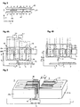
- FIGS. 1 and 2 schematically show two sectional views of a semiconductor mounting device a chip gripper 1, wherein the cuts in the yz or xz plane of a Cartesian xyz coordinate system lie.
- the semiconductor mounting device comprises one, preferably about its central axis 2 rotatable, and along the x-axis movable wafer table 3 for recording a chip in the 4th sawed wafer, a carriage 6 movable on a frame 5 in the y-direction, a first drive device 7 for moving the carriage 6 in the y-direction, a second drive device 8 for Movement of the frame 5 in the vertical z-direction and a device 9 for receiving and Transport of a substrate 10.
- the two drive devices 7, 8 are fixed to the semiconductor mounting device arranged.
- a third, also fixedly mounted drive device 11 provided for the displacement of the frame 5 and thus also of the carriage 6 with the Chip gripper 1 by relatively small distances in the x direction.
- the chips 4 are typically on a known as Nitto Tape adhesive film, which is mounted in a frame.
- the carriage 6 rolls without play on wheels 12 or slides on the frame 5 mounted on air bearings. Precise Detecting the respective position of the carriage 6, a glass scale rod 13 is attached to the frame 5, the cooperates with a arranged on the carriage 6 measuring head.
- the drive device 7 for moving the carriage 6 in the y-direction is a U-shaped stator 14, in the interior 15 of which a slider 6 attached to the rotor 16 extends.
- the stator 14 has on both sides of the inner space 15, arranged along the y-direction magnets 17, which alternately represent a north pole N or south pole S.
- Opposite magnets 17 each form a pair of magnets having a north pole N and a south pole S.
- the arrangement of the magnets 17 in the xy plane is shown in FIG.
- the interior 15 of the facing pole of the magnets 17 is denoted by N for "North Pole" and S for "South Pole”.
- the rotor 16 has a plurality of electrical windings 18 (FIG.
- the rotor 16 is movable in the z-direction by a distance d of typically 3 cm.
- the driving force acting in the y-direction is determined by the direction and strength of the magnetic field generated in the interior 15 of the stator 14 by the magnets 17 and the direction and magnitude of the currents flowing through the windings 18 in the vertical z-direction.
- FIG. 4A shows the relative position of the windings 18 to the magnets 17 when the rotor 16 is in a z-position z 1 , in which the chip gripper 1 just receives a chip 4 from the wafer table 3.
- the windings 18 are, as shown in FIGS. 4A and 4B, preferably rectangular formed and arranged on the rotor 16 so that the horizontally extending strands 19 of the Windings 18 outside of the generated by the magnets 17 in the interior 15 of the stator 14 Magnetic field are located. This ensures that during operation no force in the vertical z-direction the carriage 6 is exercised.
- the drive device 7 is preferred designed as a 2-phase or 3-phase linear motor.
- a 2-phase linear motor are respectively Pairs of windings 18a, 18b provided, wherein the two windings 18a, 18b of a pair partially overlap and wherein the two windings 18a, 18b of a pair of different Power sources 20, 21 are fed.
- a significant advantage of the multi-phase linear motor is therein to see that it can be built arbitrarily long, with only to ensure that the stator 14 is either formed sufficiently massive or on the basic structure of the semiconductor mounting device is sufficiently firmly anchored, so that the strong forces generated by the magnet 17, the stator 14th can not bend.
- the linear motor To control the linear motor, this is obtained from the glass scale 13 (FIG. 1) and the measuring head formed position measuring system used.
- the windings 18 are fixed by flexible wires with the Energy sources 20, 21 connected. Mechanical commutators for reversing the windings 18 omitted.
- a controller controls the direction, the phase and the amplitude of the through the Windings of 18 flowing currents according to the position, and possibly the instantaneous speed, of the rotor 16 relative to the magnets 17 of the stator 14, this information because of the Position measuring system available or derivable.
- a voice coil motor In another embodiment, as illustrated in FIG. 5 in a perspective view is provided as a drive device 7, a voice coil motor.
- This engine has only one Winding 18, due to their yielding in the z-direction winding 18 in the z-direction by the predetermined Distance d is freely movable.
- the voice coil motor preferably has two in the y direction the distance L separate E-shaped stators 14a, 14b, wherein the winding 18 is wider than L, so that always a portion of the winding 18 is in the magnetic field generated by the magnet 17.
- the Separation into two stators 14a, 14b prolongs the drive range in the y-direction without appreciable Losing the efficiency of the engine.
- the carriage 6 and the frame 5 are sketched only schematically. in the drawn example, the attached to the carriage 6 winding 18 forms the rotor 16th
- the semiconductor mounting device serves to feed one chip 4 after another to the wafer table 3 (FIG. 1) and to place on the substrate 10.
- the wafer table 3 ( Figure 1) is in a single horizontal direction, namely the x-direction displaceable.
- the device 9 for transporting the substrate 10 is allowed only one transport of the substrate 10 in the x direction.
- the carriage 6 takes over the transport of the chips 4 in the y direction.
- the third drive device 11 is provided, the one Displacement of the frame 5 and thus also of the carriage 6 with the chip gripper 1 in the x direction to a few tens of microns allowed.
- the transport device 9 for the substrate moves the substrate 10 cyclically forward in the x-direction by a predetermined distance. Also, the wafer table 3 each shifted in the x direction to provide the next processed chip 4.
- the carriage 6 is raised in the vertical z-direction and by means of first drive device 7 is shifted in the y-direction until the chip gripper 1 in one provided Position above the camera, not shown with respect to its xy-position exactly measured Chips 4 is located.
- the drive device 8 of the carriage 6 leading frame 5th lowered until the chip gripper 1 can lift the chip 4 by Vakkum of the adhesive film.
- the frame 5 is raised, the carriage 6 transported in the y direction and the Frame 5 again lowered until the chip 4 on the means of a second camera or a sensor measured substrate 10 is placed.
- a slight deviation of the x-position of the chip 4 of his Target position on the substrate 10 is already during the movement of the carriage 6 by means of third drive device 11 corrected. Because the distances that the slide 6 has to cover are ever After the y-position of the chip 4 on the wafer table 3 are different lengths, arise different cycle times.
- the wafer table 3 is rotatable about its central axis 2, then after the processing of the chips the first half of the wafer, the wafer table is rotated by 180 ° and then the second half of the Wafers are processed. This allows a particularly compact design of the semiconductor mounting device, which is also designed for the processing of wafers with a large diameter.
- the proposed drive devices combine high placement accuracy of the chips the substrate and great freedom in the choice of the substrate. In particular, both very narrow as well as very wide substrates at high average clock rates can be processed easily.
- the drive devices are also largely maintenance-free, since the stator and the rotor do not touch.
- neither the device for transporting the substrates nor the wafer table necessarily a drive for their displacement in the y direction.
Landscapes
- Die Bonding (AREA)
- Manipulator (AREA)
- Automatic Assembly (AREA)
- Linear Motors (AREA)
Description
- Fig. 1, 2
- Schnittdarstellungen einer Halbleiter-Montageeinrichtung,
- Fig. 3
- die Anordnung von Magneten in einem Stator einer Antriebsvorrichtung,
- Fig. 4A, B
- die vertikale Lage des Läufers im Stator in zwei verschiedenen Positionen, und
- Fig. 5
- einen Voice Coil Motor.
Claims (6)
- Halbleiter-Montageeinrichtung mit einem auf einem Rahmen (5) in einer horizontalen Richtung beweglichen Schlitten (6) und einer ersten Antriebsvorrichtung (7) zur Bewegung des Schlittens (6) auf dem Rahmen (5), wobei am Schlitten (6) ein Chipgreifer (1) befestigt ist, dadurch gekennzeichnet, dass die erste Antriebsvorrichtung (7) einen Magnete (17) aufweisenden Stator (14) und einen mit elektrischen Wicklungen (18) versehenen, am Schlitten (6) befestigten Läufer (16) umfasst, dass der Rahmen (5) mit einer zweiten Antriebsvorrichtung (8) in vertikaler Richtung bewegbar ist, dass der Läufer (16) sich in vertikaler Richtung in den Stator (14) erstreckt und dass die Wicklungen (18) des Läufers (16) in vertikaler Richtung länger als die Magnete (17) ausgebildet sind, damit sich bei einer Verschiebung des Läufers (16) in vertikaler Richtung um eine vorbestimmte Distanz (d) die die Antriebskraft bestimmende Geometrie zwischen den Magneten (17) und den Wicklungen (18) nicht ändert.
- Halbleiter-Montageeinrichtung nach Anspruch 1, dadurch gekennzeichnet, dass der Stator (14) u-förmig ist und dass sich der Läufer (16) in dessen Innenraum (15) erstreckt.
- Halbleiter-Montageeinrichtung nach Anspruch 1, dadurch gekennzeichnet, dass die erste Antriebsvorrichtung (7) als Voice Coil Motor ausgebildet ist.
- Halbleiter-Montageeinrichtung nach Anspruch 3, dadurch gekennzeichnet, dass die erste Antriebsvorrichtung (7) zwei getrennte Statoren (14a, 14b) aufweist.
- Halbleiter-Montageeinrichtung mit einem auf einem Rahmen (5) in einer horizontalen Richtung beweglichen Schlitten (6) und einer ersten Antriebsvorrichtung (7) zur Bewegung des Schlittens (6) auf dem Rahmen (5), wobei am Schlitten (6) ein Chipgreifer (1) befestigt ist, dadurch gekennzeichnet, dass die erste Antriebsvorrichtung (7) einen Magnete (17) aufweisenden Stator (14) und einen mit elektrischen Wicklungen (18) versehenen, am Schlitten (6) befestigten Läufer (16) umfasst, dass der Rahmen (5) mit einer zweiten Antriebsvorrichtung (8) in vertikaler Richtung bewegbar ist, dass der Läufer (16) sich in vertikaler Richtung in den Stator (14) erstreckt und dass die Magnete (17) in vertikaler Richtung länger als die Wicklungen (18) des Läufers (16) ausgebildet sind, damit sich bei einer Verschiebung des Läufers (16) in vertikaler Richtung um eine vorbestimmte Distanz (d) die die Antriebskraft bestimmende Geometrie zwischen den Magneten (17) und den Wicklungen (18) nicht ändert.
- Halbleiter-Montageeinrichtung nach Anspruch 5, dadurch gekennzeichnet, dass der Stator (14) u-förmig ist und dass sich der Läufer (16) in dessen Innenraum (15) erstreckt.
Priority Applications (3)
| Application Number | Priority Date | Filing Date | Title |
|---|---|---|---|
| EP98810988A EP0991110B8 (de) | 1998-10-01 | 1998-10-01 | Halbleiter-Montageeinrichtung mit einem Chipgreifer |
| AT98810988T ATE306118T1 (de) | 1998-10-01 | 1998-10-01 | Halbleiter-montageeinrichtung mit einem chipgreifer |
| DE59813092T DE59813092D1 (de) | 1998-10-01 | 1998-10-01 | Halbleiter-Montageeinrichtung mit einem Chipgreifer |
Applications Claiming Priority (1)
| Application Number | Priority Date | Filing Date | Title |
|---|---|---|---|
| EP98810988A EP0991110B8 (de) | 1998-10-01 | 1998-10-01 | Halbleiter-Montageeinrichtung mit einem Chipgreifer |
Publications (3)
| Publication Number | Publication Date |
|---|---|
| EP0991110A1 EP0991110A1 (de) | 2000-04-05 |
| EP0991110B1 true EP0991110B1 (de) | 2005-10-05 |
| EP0991110B8 EP0991110B8 (de) | 2005-12-07 |
Family
ID=8236365
Family Applications (1)
| Application Number | Title | Priority Date | Filing Date |
|---|---|---|---|
| EP98810988A Expired - Lifetime EP0991110B8 (de) | 1998-10-01 | 1998-10-01 | Halbleiter-Montageeinrichtung mit einem Chipgreifer |
Country Status (3)
| Country | Link |
|---|---|
| EP (1) | EP0991110B8 (de) |
| AT (1) | ATE306118T1 (de) |
| DE (1) | DE59813092D1 (de) |
Families Citing this family (3)
| Publication number | Priority date | Publication date | Assignee | Title |
|---|---|---|---|---|
| SG100644A1 (en) | 2000-04-04 | 2003-12-26 | Esec Trading Sa | Linear guide with air bearing |
| CH696103A5 (de) * | 2003-06-06 | 2006-12-15 | Esec Trading Sa | Halbleiter-Montageeinrichtung. |
| EP1612843A1 (de) * | 2004-07-02 | 2006-01-04 | Unaxis International Trading Ltd | Verfahren und Einrichtung fuer die Montage von Halbleiterchips |
Family Cites Families (1)
| Publication number | Priority date | Publication date | Assignee | Title |
|---|---|---|---|---|
| JP3149782B2 (ja) * | 1996-05-07 | 2001-03-26 | 松下電器産業株式会社 | ダイボンディング装置およびダイボンディング方法 |
-
1998
- 1998-10-01 EP EP98810988A patent/EP0991110B8/de not_active Expired - Lifetime
- 1998-10-01 DE DE59813092T patent/DE59813092D1/de not_active Expired - Fee Related
- 1998-10-01 AT AT98810988T patent/ATE306118T1/de not_active IP Right Cessation
Also Published As
| Publication number | Publication date |
|---|---|
| DE59813092D1 (de) | 2005-11-10 |
| EP0991110A1 (de) | 2000-04-05 |
| EP0991110B8 (de) | 2005-12-07 |
| ATE306118T1 (de) | 2005-10-15 |
Similar Documents
| Publication | Publication Date | Title |
|---|---|---|
| DE69634768T2 (de) | Vorrichtung zur Steuerung der Position eines Trägertisches, sowie Trägertischvorrichtung, Belichtungsgerät und Herstellungsverfahren unter Verwendung derselben | |
| DE69010610T2 (de) | Zweistufen- Positioniervorrichtung. | |
| DE60109635T2 (de) | Xyz-positioniereinrichtung | |
| DE3317521C2 (de) | Positionier-Vorrichtung für einen Linear-Motor | |
| DE69208190T2 (de) | Betätigungsvorrichtung | |
| DE3882584T2 (de) | Führungsvorrichtung. | |
| DE4412213C2 (de) | Linearmotor | |
| EP0317787B2 (de) | Einrichtung zur Durchführung der Zustellbewegung eines Arbeitsorgans zu einer Arbeitsstation | |
| DE60205618T2 (de) | Fadenverlegung für eine vorrichtung zum aufwickeln eines fadens auf eine spule | |
| EP2702672B1 (de) | Hochauflösende positioniereinrichtung | |
| DE69501106T2 (de) | Linearmotor zur erweiterten Bewegung | |
| DE742072T1 (de) | Symmetrische, mehrachsige, mit Linearmotoren versehene Werkzeugmaschine | |
| DE1920351A1 (de) | Elektrischer Schrittschaltmotor | |
| DE69223431T2 (de) | Linearer Antrieb | |
| DE102012104840B4 (de) | Elektrodynamisches Linearantriebsmodul | |
| DE4137385C2 (de) | Drehzahlregeleinrichtung für ein handgehaltenes Elektrowerkzeug und Verfahren zu deren Herstellung | |
| AT523217A1 (de) | Transporteinrichtung | |
| DE112005000622T5 (de) | Lineargleiter mit beweglichen Magneten | |
| CH704221B1 (de) | Vorrichtung zum Umformen von hohlzylindrischen Körpern und Verfahren zum Betreiben dieser Vorrichtung. | |
| DE102004026534B4 (de) | Halbleiter-Montageeinrichtung | |
| DE2441588C2 (de) | Magnetische Positioniereinrichtung mit zwei linearen Schrittmotoren | |
| DE2821552C2 (de) | Elektronische Nähmaschine | |
| DE69008654T2 (de) | Linearmotor sowie mit mindestens einem Linearmotor versehene Positionierungsvorrichtung. | |
| JPH0132654B2 (de) | ||
| EP0991110A1 (de) | Halbleiter-Montageeinrichtung mit einem Chipgreifer |
Legal Events
| Date | Code | Title | Description |
|---|---|---|---|
| PUAI | Public reference made under article 153(3) epc to a published international application that has entered the european phase |
Free format text: ORIGINAL CODE: 0009012 |
|
| AK | Designated contracting states |
Kind code of ref document: A1 Designated state(s): AT CH DE FR IT LI |
|
| AX | Request for extension of the european patent |
Free format text: AL;LT;LV;MK;RO;SI |
|
| 17P | Request for examination filed |
Effective date: 20001005 |
|
| AKX | Designation fees paid |
Free format text: AT CH DE FR IT LI |
|
| RAP1 | Party data changed (applicant data changed or rights of an application transferred) |
Owner name: ESEC TRADING SA |
|
| 17Q | First examination report despatched |
Effective date: 20031212 |
|
| GRAP | Despatch of communication of intention to grant a patent |
Free format text: ORIGINAL CODE: EPIDOSNIGR1 |
|
| GRAS | Grant fee paid |
Free format text: ORIGINAL CODE: EPIDOSNIGR3 |
|
| GRAA | (expected) grant |
Free format text: ORIGINAL CODE: 0009210 |
|
| AK | Designated contracting states |
Kind code of ref document: B1 Designated state(s): AT CH DE FR IT LI |
|
| PG25 | Lapsed in a contracting state [announced via postgrant information from national office to epo] |
Ref country code: IT Free format text: LAPSE BECAUSE OF FAILURE TO SUBMIT A TRANSLATION OF THE DESCRIPTION OR TO PAY THE FEE WITHIN THE PRESCRIBED TIME-LIMIT;WARNING: LAPSES OF ITALIAN PATENTS WITH EFFECTIVE DATE BEFORE 2007 MAY HAVE OCCURRED AT ANY TIME BEFORE 2007. THE CORRECT EFFECTIVE DATE MAY BE DIFFERENT FROM THE ONE RECORDED. Effective date: 20051005 |
|
| REG | Reference to a national code |
Ref country code: CH Ref legal event code: NV Representative=s name: PATENTANWALTSBUERO DR. URS FALK Ref country code: CH Ref legal event code: EP |
|
| RAP2 | Party data changed (patent owner data changed or rights of a patent transferred) |
Owner name: UNAXIS INTERNATIONAL TRADING LTD |
|
| REF | Corresponds to: |
Ref document number: 59813092 Country of ref document: DE Date of ref document: 20051110 Kind code of ref document: P |
|
| PLBE | No opposition filed within time limit |
Free format text: ORIGINAL CODE: 0009261 |
|
| STAA | Information on the status of an ep patent application or granted ep patent |
Free format text: STATUS: NO OPPOSITION FILED WITHIN TIME LIMIT |
|
| 26N | No opposition filed |
Effective date: 20060706 |
|
| PG25 | Lapsed in a contracting state [announced via postgrant information from national office to epo] |
Ref country code: FR Free format text: LAPSE BECAUSE OF FAILURE TO SUBMIT A TRANSLATION OF THE DESCRIPTION OR TO PAY THE FEE WITHIN THE PRESCRIBED TIME-LIMIT Effective date: 20061020 |
|
| EN | Fr: translation not filed | ||
| PG25 | Lapsed in a contracting state [announced via postgrant information from national office to epo] |
Ref country code: AT Free format text: LAPSE BECAUSE OF NON-PAYMENT OF DUE FEES Effective date: 20061001 |
|
| REG | Reference to a national code |
Ref country code: CH Ref legal event code: PUE Owner name: OERLIKON ASSEMBLY EQUIPMENT AG, STEINHAUSEN Free format text: UNAXIS INTERNATIONAL TRADING LTD#HINTERBERGSTRASSE 32 POSTFACH 5503#6330 CHAM (CH) -TRANSFER TO- OERLIKON ASSEMBLY EQUIPMENT AG, STEINHAUSEN#HINTERBERGSTRASSE 32#6330 CHAM (CH) |
|
| PG25 | Lapsed in a contracting state [announced via postgrant information from national office to epo] |
Ref country code: FR Free format text: LAPSE BECAUSE OF FAILURE TO SUBMIT A TRANSLATION OF THE DESCRIPTION OR TO PAY THE FEE WITHIN THE PRESCRIBED TIME-LIMIT Effective date: 20051005 |
|
| PGFP | Annual fee paid to national office [announced via postgrant information from national office to epo] |
Ref country code: DE Payment date: 20081014 Year of fee payment: 11 Ref country code: CH Payment date: 20081016 Year of fee payment: 11 |
|
| REG | Reference to a national code |
Ref country code: CH Ref legal event code: PL |
|
| PG25 | Lapsed in a contracting state [announced via postgrant information from national office to epo] |
Ref country code: DE Free format text: LAPSE BECAUSE OF NON-PAYMENT OF DUE FEES Effective date: 20100501 |
|
| PG25 | Lapsed in a contracting state [announced via postgrant information from national office to epo] |
Ref country code: LI Free format text: LAPSE BECAUSE OF NON-PAYMENT OF DUE FEES Effective date: 20091031 Ref country code: CH Free format text: LAPSE BECAUSE OF NON-PAYMENT OF DUE FEES Effective date: 20091031 |