EP0991067B1 - Disk recording and/or reproducing apparatus - Google Patents
Disk recording and/or reproducing apparatus Download PDFInfo
- Publication number
- EP0991067B1 EP0991067B1 EP99307614A EP99307614A EP0991067B1 EP 0991067 B1 EP0991067 B1 EP 0991067B1 EP 99307614 A EP99307614 A EP 99307614A EP 99307614 A EP99307614 A EP 99307614A EP 0991067 B1 EP0991067 B1 EP 0991067B1
- Authority
- EP
- European Patent Office
- Prior art keywords
- disk
- opening
- sheet
- closing
- opening portion
- Prior art date
- Legal status (The legal status is an assumption and is not a legal conclusion. Google has not performed a legal analysis and makes no representation as to the accuracy of the status listed.)
- Expired - Lifetime
Links
Images


Classifications
-
- G—PHYSICS
- G11—INFORMATION STORAGE
- G11B—INFORMATION STORAGE BASED ON RELATIVE MOVEMENT BETWEEN RECORD CARRIER AND TRANSDUCER
- G11B33/00—Constructional parts, details or accessories not provided for in the other groups of this subclass
- G11B33/02—Cabinets; Cases; Stands; Disposition of apparatus therein or thereon
- G11B33/027—Covers
-
- G—PHYSICS
- G11—INFORMATION STORAGE
- G11B—INFORMATION STORAGE BASED ON RELATIVE MOVEMENT BETWEEN RECORD CARRIER AND TRANSDUCER
- G11B17/00—Guiding record carriers not specifically of filamentary or web form, or of supports therefor
- G11B17/02—Details
- G11B17/04—Feeding or guiding single record carrier to or from transducer unit
- G11B17/0401—Details
- G11B17/0405—Closing mechanism, e.g. door
Definitions
- the present invention relates to a disk recording and/or reproducing apparatus in which an opening/closing means is mounted to an opening portion allowing insertion or discharge of a disk therethrough, wherein the apparatus is intended to attain the suitable insertion or discharge operation of the disk without degrading the function of the opening/closing means.
- disk recording and/or reproducing apparatuses for example, disk players capable of recording and/or reproducing an optical disk or a magnetic disk
- a type provided with an opening/closing means for opening/closing an opening portion allowing insertion or discharge of a disk therethrough for example, a sheet formed of a synthetic fiber sheet.
- Such a sheet is provided for preventing damages of a disk upon insertion or discharge of the disk, shielding the inner structure of the apparatus, and preventing permeation of dust in the apparatus.
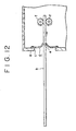
- Figs. 11 and 12 show a portion of a disk player provided with such a sheet.
- a front surface portion "a” of the disk player has an opening portion "c” through which a disk “b” is to be inserted in or discharged from the disk player.
- a sheet “d” having a laterally-elongated rectangular shape is mounted on the back surface of the front surface portion "a” by a suitable means such as fusion in such a manner as to cover the opening portion "c" from the back surface side.
- the sheet “d” is formed of typically a synthetic fiber sheet having a specific flexibility.
- the upper and lower ends of the sheet “d” are mounted on the upper and lower opening edges of the opening portion “c” , respectively.
- the sheet “d” has, at its center in the vertical direction, a slit “e” extending longer in the lateral direction, through which the disk "b” is to be inserted in or discharged from the disk player.
- rollers "f” are provided in the disk player in such a manner as to be rotatably supported by supporting members (not shown).
- the rollers "f” are adapted to hold the disk “b” in the vertical direction and to be rotated in specific directions reversed to each other for drawing the disk “b” in the disk player or drawing it out of the opening portion "c".
- the disk player provided with the sheet “d” for opening/closing the opening portion “c” as described above has a problem.
- the disk “b” When passing through the slit “e", the disk “b” is brought into contact with the sheet “d”, with a result that a load is applied from the sheet “d” on the disk “b” moved to be inserted in or discharged from the disk player.
- the load is imparted to the rollers "f” via the disk "b”, to obstruct the suitable insertion or discharge operation of the disk "b".
- the IBM Technical Disclosure Bulletin, Vol. 33, No. 3A, p140-142 entitled "File Anti-Contamination Doors” discloses a door device for a compact disk cartridge, in which an opening in the apparatus through which the cartridge may be inserted or discharged is closed by a pair of doors which are deformable by the cartridge to open/close the opening.
- US-5,265,951 discloses a shield placed over the port of a card reader of an electronic computing device through which a card may be inserted, the shield being an integrally moulded one-piece member which includes two flexible flaps on opposite sides of an elongated slit.
- a disk recording and/or reproducing apparatus comprising:
- each of the disk recording and/or reproducing apparatuses it is possible to reduce a load applied from the opening/closing portions on a disk moved to be inserted or discharged from the apparatus. Accordingly, the hereinafter described embodiment of the present invention can optimize the insertion or discharge operation of a disk without degrading the function of an opening/closing portions.
- the disk recording and/or reproducing apparatus is applied to a disk player used as car audio equipment for reproducing an optical disk.
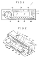
- a disk player 1 including a housing 2, a sub-panel 3, and a front panel 4. Necessary members are disposed in the housing 2.
- the housing 2 having a box-shape opened forwardly is formed by mounting a top board 2b from above on a main body 2a opened forwardly and upwardly.
- the sub-panel 3 is mounted to the housing 2 in such a manner as to cover the front side of the housing 2.
- the upper end portion of the sub-panel 3 has an opening portion 5 extending longer in the lateral direction.
- the width of the opening portion 5 in the lateral direction is set to be slightly larger than the outside diameter of a disk 6.
- the width of the opening portion 5 in the vertical direction is set to become large in the direction from each of the right and left ends to the center of the opening portion 5.
- the front panel 4 is formed into an approximately rectangular shape elongated in the lateral direction.
- a plurality of operational buttons 4a for carrying out various operations and a display portion 4b for displaying an operational state are provided on the front surface of the front panel 4.
- the front panel 4 is supported by the housing 2 via two first arms 7 and two second arms 8 in such a manner as to be movable between a first position at which the disk 6 cannot be inserted from the opening portion 5 and a second position at which the disk 6 can be inserted from the opening portion 5.
- the front ends of the first arms 7 are turnably supported by the housing 2 in such a manner as to be substantially in the vertical direction, and the upper ends of the right and left end portions of the front panel 4 are turnably supported by the first arms 7.
- the second arms 8 are supported by the housing 2 in such a manner as to be movable in the longitudinal direction, and the lower ends of the right and left end portions of the front panel 4 are turnably supported by the second arms 8.
- the front panel 4 In the state in which the front panel 4 is located at the first position, if the front ends of the first arms 7 are turned to be moved downwardly and simultaneously the second arms 8 are moved forwardly, the upper end of the front panel 4 is moved downwardly along the front surface of the sub-panel 3 and simultaneously the lower end of the front panel 4 is tilted in such a manner as to be protruded forwardly.
- the front panel 4 at the first position is thus moved to the second position shown in Figs. 2 to 4, at which the disk 6 can be inserted in or discharged from the housing 2 through the opening portion 5 formed in the sub-panel 3.
- the above operation of the front panel 4 is performed by depressing one of the operating buttons 4a provided on the front panel 4 to actuate a drive mechanism (not shown), provided in the housing 2, to which the first arms 7 and the second arms 8 are connected.
- a sheet 9 is mounted on the sub-panel 3.
- the sheet 9 is formed of a synthetic fiber sheet having a specific flexibility, for example, a suede-like artificial leather sheet sold by Toray Industries, Inc. under the trade name "ECSAINE", and has an approximately rectangular shape elongated in the lateral direction and being larger than the opening portion 5.
- the sheet 9 is composed of a first member 10 and a second member 11 which are identical to each other in terms of the size and shape.
- the upper end portion of the first member 10 is fused, at a plurality of fusion points 10a, to an upper opening edge 5a of the opening portion 5 on the back surface of the sub-panel 3, and the lower end portion of the second member 11 is fused, at a plurality of fusion points 11a, to a lower opening edge 5b of the opening portion 5 on the back surface of the sub-panel 3.
- the lower end of the first member 10 and the upper end of the second member 11 are butted to each other to form a butt portion 12.
- the disk 6 is inserted in or discharged from the housing 2 through the butt portion 12.
- the opening portion 5 is covered with the sheet 9 from the back side.
- Portions of the sheet 9 defined by excluding the upper and lower end portions from the sheet 9 play a role of opening/closing the opening portion 5.
- a portion 13 defined by excluding the upper end portion of the first member 10 from the first member 10 and a portion 14 defined by excluding the lower end portion of the second member 11 from the second member 11 are deflected in a specific direction when the disk 6 is inserted in or discharged from the housing 2 and are returned to the original states after the disk 6 is inserted in or discharged from the housing 2, to open/close the opening portion 5.
- the portions 13 and 14 function as first and second opening/closing portions for opening/closing the opening portion 5, respectively.
- a plurality of notches 13a, each of which extends in the lateral direction, are formed in the first opening/closing portion 13 of the first member 10 in such a manner as to be spaced from each other.
- a plurality of notches 14a, each of which extends in the lateral direction are formed in the second opening/closing portion 14 of the second member 11 in such a manner as to be spaced from each other.
- a distance from the butt portion 12 to each of the notches 13a is set to be equal to that from the butt portion 12 to each of the notches 14a.
- the notches 13a and 14a function as a deforming portion for facilitating the deformation (deflection) of the first and second opening/closing portions 13 and 14 when the disk 6 is inserted in or discharged from the housing 2.
- a mechanical deck 15 is provided in the housing 2, and two rollers 16 are rotatably supported by the mechanical deck 15.
- the rollers 16 are rotated in a state in which they hold the disk 6 therebetween, thereby moving the disk 6 in a specific direction.
- Each roller 16 is composed of a shaft 16a to be supported, around which a cylindrical roller portion 16b made from an elastic member such as rubber is fixed. Both end portions of the shaft 16a of each roller 16 are rotatably supported by both side surface portions of the mechanical deck 15. Each roller 16 can be rotated normally and reversely by a roller drive mechanism (not shown) provided in the housing 2.
- the disk 6 When inserted up to a specific position, the disk 6 is vertically held between the rollers 16, and is drawn in the housing 2 by rotation of the rollers 16.
- the disk 6 After termination of the drawl of the disk 6 in the housing 2 by rotation of the rollers 16, the disk 6 is mounted on a mounting portion (not shown) disposed in the housing 2.
- the front panel 4 is then moved from the second position to the first position. After that, the reproducing operation of the disk 6 is started by depressing one of the operational buttons 4a.
- the mounting state of the disk 6 on the mounting portion is released by depressing one of the operational buttons 4a.
- the front panel 4 is moved from the first position to the second position, and the disk 6 is held between the rollers 16 again and is drawn out of the opening portion 5 through the butt portion 12 of the sheet 9 by rotation of the rollers 16.
- the first and second opening/closing portions 13 and 14 are deflected outwardly by amounts corresponding to the thickness of the disk 6. Even upon this discharge of the disk 6, since the notches 13a and 14a are formed in the sheet 9, the first and second opening/closing portions 13 and 14 are easily deformed and thereby a load applied from the sheet 9 on the disk 6 is made small. Accordingly, the disk 6 can be smoothly discharged by rotation of the rollers 16.
- the sheet 9 has the notches 13a and 14a formed as the deforming portions for facilitating the deformation of the first and second opening/closing portions 13 and 14. Accordingly, it is possible to make smooth the insertion or discharge of the disk 6 without degrading the function of the sheet 9 and to prevent the disk 6 being from damaged due to a load applied from the sheet 9 on the disk 6.
- the disk player 1 is used as car audio equipment generally required to be thinned. Accordingly, the vertical width of the opening portion 5 is necessarily made small, so that a distance (designated by character L in Fig. 6) from the butt portion 12 of the sheet 9 to the mounting portion (fusion points 10a and 11a) mounted on the equipment cannot be sufficiently large. As a result, the first and second opening/closing portions 13 and 14 of the sheet 9 are hard to be deformed upon insertion or discharge of the disk 6, and thereby a load applied from the sheet 9 on the disk 6 becomes larger.
- the sheet 9 can be easily deformed. Accordingly, in the equipment in which the above distance L cannot be made sufficiently large, the formation of the notches 13a and 14a in the sheet 9 is particularly effective as the means for reducing a load applied from the sheet 9 on the disk 6.
- the notches 13a and 14a are formed in the sheet 9 in such a manner as to extend in the lateral direction, that is, in parallel to the extending direction of the opening portion 5, the first and second opening/closing portions 13 and 14 are very easily deformed, to thereby effectively reduce a load applied from the sheet 9 on the disk 6.
- the first and second opening/closing portions 13a and 14a are more easily deformed, to thereby more effectively reduce a load applied from the sheet 9 on the disk 6.
- the sheet 9 composed of the first and second members 10 and 11 is mounted to the sub-panel 3 in the state in which the lower end of the first member 10 is butted to the upper end of the second member 11; however, the sheet may be configured as a sheet 9A shown in Fig. 8, in which the sheet 9A is mounted to the sub-panel 3 in a state in which the first member 10 is partially overlapped to the second member 11.
- Figs. 9 and 10 show a sheet 9B formed of only one member.
- the sheet 9B has the same configuration as that of the sheet 9 except that the sheet 9B is formed of only one member and it has a slit through which the disk 6 is to be inserted in or discharged from the housing 2, and therefore, only different points between the sheet 9 and the sheet 9B will be described in detail, and the parts corresponding to those of the sheet 9 are designated by the same characters and the description thereof is omitted.
- the sheet 9B is formed of a synthetic fiber sheet having an approximately rectangular shape being elongated in the lateral direction and being larger than the opening portion 5.
- the upper and lower end portions of the sheet 9B are fused, at a plurality of fusion points 17, to the upper opening edge 5a of the opening portion 5 on the back surface of the sub-panel 3.
- the sheet 9B has, at its center in the vertical direction, a first slit 18 which extends longer in the lateral direction between positions near the right and left ends of the sheet 9B.
- the sheet 9B also has, at its right and left end portions, two second slits 19 each of which extends in the vertical direction between positions near the upper and lower ends of the sheet 9B and is connected at its center to one of both the ends of the first slit 18.
- Portions of the sheet 9B excluding the peripheral edge portions, that is, portions 20 and 21 located above and below the first slit 18 in such a manner as to correspond to the opening portion 5 function as first and second opening/closing portions for opening/closing the opening portion 5.
- first and second opening/closing portions for opening/closing the opening portion 5.
- a plurality of notches 20a and a plurality of notches 21a each extending in the lateral direction are formed in the first and second opening/closing portions 20 and 21, respectively.
- the sheet 9B exhibits the same effect as that obtained by the sheet 9.
- the sheet 9B is effective to make smooth the insertion or discharge of the disk 6 without degrading the function of the sheet 9B and to prevent the disk 6 being from damaged due to a load applied from the sheet 9B on the disk 6.
- the sheet 9B formed of only one member has another advantage in reducing the number of parts.
- a plurality of the notches 13a and 14a are formed as the deforming portion; however, the number and length of the notches 13a and 14a (13a and 14a, 20a and 21a) may be set such that a load applied from the sheet 9 (9A, 9B) on the disk 6 becomes not more than a specific value in consideration of the thickness and hardness of the sheet 9 (9A, 9B).
- a thinned portion may be formed on the sheet 9 (9A, 9B).
- the configuration of the present invention in which the notches 13a and 14a (13a and 14a, 20a and 21a) are formed in the sheet 9 (9A, 9B) for reducing a load applied to the disk 6 when the disk 6 is inserted in or discharged from the housing 2, can be applied to various kinds of equipment of a so-called slot-in type in which a disk is inserted from an opening portion formed in the equipment.
Description
- The present invention relates to a disk recording and/or reproducing apparatus in which an opening/closing means is mounted to an opening portion allowing insertion or discharge of a disk therethrough, wherein the apparatus is intended to attain the suitable insertion or discharge operation of the disk without degrading the function of the opening/closing means.
- Of disk recording and/or reproducing apparatuses, for example, disk players capable of recording and/or reproducing an optical disk or a magnetic disk, there is known a type provided with an opening/closing means for opening/closing an opening portion allowing insertion or discharge of a disk therethrough, for example, a sheet formed of a synthetic fiber sheet. Such a sheet is provided for preventing damages of a disk upon insertion or discharge of the disk, shielding the inner structure of the apparatus, and preventing permeation of dust in the apparatus.
- Figs. 11 and 12 show a portion of a disk player provided with such a sheet.
- A front surface portion "a" of the disk player has an opening portion "c" through which a disk "b" is to be inserted in or discharged from the disk player. A sheet "d" having a laterally-elongated rectangular shape is mounted on the back surface of the front surface portion "a" by a suitable means such as fusion in such a manner as to cover the opening portion "c" from the back surface side.
- The sheet "d" is formed of typically a synthetic fiber sheet having a specific flexibility. The upper and lower ends of the sheet "d" are mounted on the upper and lower opening edges of the opening portion "c", respectively. The sheet "d" has, at its center in the vertical direction, a slit "e" extending longer in the lateral direction, through which the disk "b" is to be inserted in or discharged from the disk player.
- Two rollers "f" are provided in the disk player in such a manner as to be rotatably supported by supporting members (not shown). The rollers "f" are adapted to hold the disk "b" in the vertical direction and to be rotated in specific directions reversed to each other for drawing the disk "b" in the disk player or drawing it out of the opening portion "c".
- To be more specific, when the disk "b" is inserted from the opening portion "c" up to a specific position through the slit "e" of the sheet "d", it is held between the rollers "f" and is then drawn inwardly by rotation of the rollers "f". At this time, since the disk "b" is inserted through the slit "e", the portion of the sheet "d" being in contact with the disk "b" is deflected inwardly as shown in Fig. 12.
- When the disk "b" is drawn out of the opening portion "c" through the slit "e" by rotation of the rollers "f", the portion of the sheet "d" being in contact with the disk "b" is deflected in the direction reversed to that upon drawl of the disk "b" in the disk player, that is, deflected outwardly.
- The disk player provided with the sheet "d" for opening/closing the opening portion "c" as described above, however, has a problem. When passing through the slit "e", the disk "b" is brought into contact with the sheet "d", with a result that a load is applied from the sheet "d" on the disk "b" moved to be inserted in or discharged from the disk player. The load is imparted to the rollers "f" via the disk "b", to obstruct the suitable insertion or discharge operation of the disk "b".
- In particular, if there are variations in thickness and/or hardness of the sheet "d", the degree of obstruction to the movement of the disk "b" is changed depending on the degree of the variations, and at the worst case, the insertion or discharge operation of the disk "b" by rotation of the rollers "f" are interrupted.
- For example, the IBM Technical Disclosure Bulletin, Vol. 33, No. 3A, p140-142 entitled "File Anti-Contamination Doors" discloses a door device for a compact disk cartridge, in which an opening in the apparatus through which the cartridge may be inserted or discharged is closed by a pair of doors which are deformable by the cartridge to open/close the opening.
- Similarly, US-5,265,951 discloses a shield placed over the port of a card reader of an electronic computing device through which a card may be inserted, the shield being an integrally moulded one-piece member which includes two flexible flaps on opposite sides of an elongated slit.
- According to the present invention, there is provided a disk recording and/or reproducing apparatus comprising:
- a loading means for drawing into the.apparatus a disk which is inserted through an opening portion in said apparatus and for drawing a disk which is held in said apparatus out of said opening portion; and
- an opening/closing means having first and second opening/closing portions, which are deformable by said disk to thereby open/close said opening portion, wherein at least one of said first and second opening/closing portions has at least one notch for facilitating the deformation of said opening/closing portion when said opening/closing portion is deformed by said disk drawn by said loading means.
-
- With the above configuration of each of the disk recording and/or reproducing apparatuses according to the present invention, it is possible to reduce a load applied from the opening/closing portions on a disk moved to be inserted or discharged from the apparatus. Accordingly, the hereinafter described embodiment of the present invention can optimize the insertion or discharge operation of a disk without degrading the function of an opening/closing portions.
- Hereinafter embodiments of a disk recording and/or reproducing apparatus according to the present invention will be described by way of non-limitative example with reference to the accompanying drawings in which:
- Fig. 1 is a schematic front view of a disk player of the present invention;
- Fig. 2 is a schematic perspective view showing part of the disk player;
- Fig. 3 is a schematic plan view, with parts partially cutaway, of the disk player in a state in which a disk is inserted in the disk player;
- Fig. 4 is a schematic side view, with parts partially cutaway, of the disk player in the state in which the disk is inserted in the disk player;
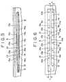
- Fig. 5 is an enlarged front view of an essential portion of the disk player;
- Fig. 6 is an enlarged rear view of an essential portion of the disk player;
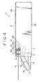
- Fig. 7 is an enlarged vertical sectional view of an essential portion of the disk player;
- Fig. 8 is an enlarged vertical sectional view of a sheet provided in a state in which members of the sheet are partially overlapped to each other;
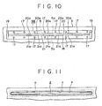
- Fig. 9 is an enlarged plan view of a sheet formed of only one member;
- Fig. 10 is an enlarged rear view of the sheet shown in Fig. 9;
- Fig. 11 is an enlarged front view of a related art disk player, showing an opening portion and a sheet covering the opening portion; and
- Fig. 12 is an enlarged vertical sectional view of the related art disk player shown in Fig. 11, showing a state in which a disk is inserted in the disk player.
-
- In the embodiments, the disk recording and/or reproducing apparatus according to the present invention is applied to a disk player used as car audio equipment for reproducing an optical disk.
- Referring to Figs. 1 to 4, there is shown a
disk player 1 including ahousing 2, asub-panel 3, and afront panel 4. Necessary members are disposed in thehousing 2. - The
housing 2 having a box-shape opened forwardly is formed by mounting atop board 2b from above on amain body 2a opened forwardly and upwardly. - The
sub-panel 3 is mounted to thehousing 2 in such a manner as to cover the front side of thehousing 2. The upper end portion of thesub-panel 3 has anopening portion 5 extending longer in the lateral direction. The width of theopening portion 5 in the lateral direction is set to be slightly larger than the outside diameter of adisk 6. The width of theopening portion 5 in the vertical direction is set to become large in the direction from each of the right and left ends to the center of theopening portion 5. - The
front panel 4 is formed into an approximately rectangular shape elongated in the lateral direction. A plurality ofoperational buttons 4a for carrying out various operations and adisplay portion 4b for displaying an operational state are provided on the front surface of thefront panel 4. - The
front panel 4 is supported by thehousing 2 via twofirst arms 7 and twosecond arms 8 in such a manner as to be movable between a first position at which thedisk 6 cannot be inserted from theopening portion 5 and a second position at which thedisk 6 can be inserted from theopening portion 5. - The front ends of the
first arms 7 are turnably supported by thehousing 2 in such a manner as to be substantially in the vertical direction, and the upper ends of the right and left end portions of thefront panel 4 are turnably supported by thefirst arms 7. Thesecond arms 8 are supported by thehousing 2 in such a manner as to be movable in the longitudinal direction, and the lower ends of the right and left end portions of thefront panel 4 are turnably supported by thesecond arms 8. - In the state in which the
front panel 4 is located at the first position, if the front ends of thefirst arms 7 are turned to be moved downwardly and simultaneously thesecond arms 8 are moved forwardly, the upper end of thefront panel 4 is moved downwardly along the front surface of thesub-panel 3 and simultaneously the lower end of thefront panel 4 is tilted in such a manner as to be protruded forwardly. Thefront panel 4 at the first position is thus moved to the second position shown in Figs. 2 to 4, at which thedisk 6 can be inserted in or discharged from thehousing 2 through theopening portion 5 formed in thesub-panel 3. On the contrary, in the state in which thefront panel 4 is located at the second position, if thefirst arms 7 are turned to be moved upwardly and simultaneously thesecond arms 8 are moved backwardly, the upper end of thefront panel 4 is moved upwardly along the front surface of thesub-panel 3 and simultaneously the lower end of thefront panel 4 is moved backwardly. Thefront panel 4 at the second position is thus moved to the first position shown in Fig. 1, at which thedisk 6 cannot be inserted in or discharged from thehousing 2 through theopening portion 5 formed in thesub-panel 3. - The above operation of the
front panel 4 is performed by depressing one of theoperating buttons 4a provided on thefront panel 4 to actuate a drive mechanism (not shown), provided in thehousing 2, to which thefirst arms 7 and thesecond arms 8 are connected. - Referring to Figs. 4 to 7, a
sheet 9 is mounted on thesub-panel 3. - The
sheet 9 is formed of a synthetic fiber sheet having a specific flexibility, for example, a suede-like artificial leather sheet sold by Toray Industries, Inc. under the trade name "ECSAINE", and has an approximately rectangular shape elongated in the lateral direction and being larger than theopening portion 5. Thesheet 9 is composed of afirst member 10 and asecond member 11 which are identical to each other in terms of the size and shape. - Referring to Figs. 6 and 7, the upper end portion of the
first member 10 is fused, at a plurality offusion points 10a, to an upperopening edge 5a of theopening portion 5 on the back surface of thesub-panel 3, and the lower end portion of thesecond member 11 is fused, at a plurality of fusion points 11a, to a loweropening edge 5b of theopening portion 5 on the back surface of thesub-panel 3. In the state in which thefirst member 10 and thesecond member 11 of thesheet 9 are fused to theopening edges opening portion 5 as described above, the lower end of thefirst member 10 and the upper end of thesecond member 11 are butted to each other to form abutt portion 12. Thedisk 6 is inserted in or discharged from thehousing 2 through thebutt portion 12. In addition, since thesheet 9 is mounted on thesub-panel 3 as described above, theopening portion 5 is covered with thesheet 9 from the back side. - Portions of the
sheet 9 defined by excluding the upper and lower end portions from thesheet 9 play a role of opening/closing theopening portion 5. To be more specific, aportion 13 defined by excluding the upper end portion of thefirst member 10 from thefirst member 10 and aportion 14 defined by excluding the lower end portion of thesecond member 11 from thesecond member 11 are deflected in a specific direction when thedisk 6 is inserted in or discharged from thehousing 2 and are returned to the original states after thedisk 6 is inserted in or discharged from thehousing 2, to open/close theopening portion 5. Accordingly, theportions opening portion 5, respectively. - A plurality of
notches 13a, each of which extends in the lateral direction, are formed in the first opening/closingportion 13 of thefirst member 10 in such a manner as to be spaced from each other. Similarly, a plurality ofnotches 14a, each of which extends in the lateral direction, are formed in the second opening/closingportion 14 of thesecond member 11 in such a manner as to be spaced from each other. A distance from thebutt portion 12 to each of thenotches 13a is set to be equal to that from thebutt portion 12 to each of thenotches 14a. Thenotches closing portions disk 6 is inserted in or discharged from thehousing 2. - Referring back to Figs. 3 and 4, a
mechanical deck 15 is provided in thehousing 2, and tworollers 16 are rotatably supported by themechanical deck 15. Therollers 16 are rotated in a state in which they hold thedisk 6 therebetween, thereby moving thedisk 6 in a specific direction. - Each
roller 16 is composed of ashaft 16a to be supported, around which acylindrical roller portion 16b made from an elastic member such as rubber is fixed. Both end portions of theshaft 16a of eachroller 16 are rotatably supported by both side surface portions of themechanical deck 15. Eachroller 16 can be rotated normally and reversely by a roller drive mechanism (not shown) provided in thehousing 2. - When one of the
operational buttons 4a provided on thefront panel 4 is depressed and thereby thefront panel 4 is moved from the first position to the second position as described above, theopening portion 5 formed in thesub-panel 3 emerges on the front side of the disk player. Thedisk 6 is then inserted from thebutt portion 12 of thesheet 9. At this time, the first and second opening/closing portions disk 6. - When inserted up to a specific position, the
disk 6 is vertically held between therollers 16, and is drawn in thehousing 2 by rotation of therollers 16. - At this time, part of the
disk 6 is in contact with the first opening/closingportion 13 of thefirst member 10 and the second opening/closingportion 14 of thesecond member 12; however, since thenotches sheet 9, the first and second opening/closing portions sheet 9 onto thedisk 6 is made small. As a result, the drawl of thedisk 6 in thehousing 2 by rotation of therollers 16 can be smoothly performed. - After termination of the drawl of the
disk 6 in thehousing 2 by rotation of therollers 16, thedisk 6 is mounted on a mounting portion (not shown) disposed in thehousing 2. Thefront panel 4 is then moved from the second position to the first position. After that, the reproducing operation of thedisk 6 is started by depressing one of theoperational buttons 4a. - After termination of the reproducing operation of the
disk 6, the mounting state of thedisk 6 on the mounting portion is released by depressing one of theoperational buttons 4a. At this time, thefront panel 4 is moved from the first position to the second position, and thedisk 6 is held between therollers 16 again and is drawn out of theopening portion 5 through thebutt portion 12 of thesheet 9 by rotation of therollers 16. - When the
disk 6 is discharged through thebutt portion 12, the first and second opening/closing portions disk 6. Even upon this discharge of thedisk 6, since thenotches sheet 9, the first and second opening/closing portions sheet 9 on thedisk 6 is made small. Accordingly, thedisk 6 can be smoothly discharged by rotation of therollers 16. - As described above, according to the
disk player 1 of the present invention, thesheet 9 has thenotches closing portions disk 6 without degrading the function of thesheet 9 and to prevent thedisk 6 being from damaged due to a load applied from thesheet 9 on thedisk 6. - The
disk player 1 is used as car audio equipment generally required to be thinned. Accordingly, the vertical width of theopening portion 5 is necessarily made small, so that a distance (designated by character L in Fig. 6) from thebutt portion 12 of thesheet 9 to the mounting portion (fusion points 10a and 11a) mounted on the equipment cannot be sufficiently large. As a result, the first and second opening/closing portions sheet 9 are hard to be deformed upon insertion or discharge of thedisk 6, and thereby a load applied from thesheet 9 on thedisk 6 becomes larger. - According to the present invention, however, only by forming the
notches sheet 9, thesheet 9 can be easily deformed. Accordingly, in the equipment in which the above distance L cannot be made sufficiently large, the formation of thenotches sheet 9 is particularly effective as the means for reducing a load applied from thesheet 9 on thedisk 6. - In the
disk player 1, since thenotches sheet 9 in such a manner as to extend in the lateral direction, that is, in parallel to the extending direction of theopening portion 5, the first and second opening/closing portions sheet 9 on thedisk 6. - Since the plurality of the
notches 13a and the plurality of thenotches 14a are formed, the first and second opening/closing portions sheet 9 on thedisk 6. - In this embodiment, the
sheet 9 composed of the first andsecond members sub-panel 3 in the state in which the lower end of thefirst member 10 is butted to the upper end of thesecond member 11; however, the sheet may be configured as asheet 9A shown in Fig. 8, in which thesheet 9A is mounted to thesub-panel 3 in a state in which thefirst member 10 is partially overlapped to thesecond member 11. - Figs. 9 and 10 show a
sheet 9B formed of only one member. - The
sheet 9B has the same configuration as that of thesheet 9 except that thesheet 9B is formed of only one member and it has a slit through which thedisk 6 is to be inserted in or discharged from thehousing 2, and therefore, only different points between thesheet 9 and thesheet 9B will be described in detail, and the parts corresponding to those of thesheet 9 are designated by the same characters and the description thereof is omitted. - Like the
sheet 9, thesheet 9B is formed of a synthetic fiber sheet having an approximately rectangular shape being elongated in the lateral direction and being larger than the openingportion 5. - The upper and lower end portions of the
sheet 9B are fused, at a plurality of fusion points 17, to theupper opening edge 5a of theopening portion 5 on the back surface of thesub-panel 3. Thesheet 9B has, at its center in the vertical direction, afirst slit 18 which extends longer in the lateral direction between positions near the right and left ends of thesheet 9B. Thesheet 9B also has, at its right and left end portions, twosecond slits 19 each of which extends in the vertical direction between positions near the upper and lower ends of thesheet 9B and is connected at its center to one of both the ends of thefirst slit 18. - Portions of the
sheet 9B excluding the peripheral edge portions, that is,portions first slit 18 in such a manner as to correspond to theopening portion 5 function as first and second opening/closing portions for opening/closing theopening portion 5. Like thenotches sheet 9, a plurality ofnotches 20a and a plurality ofnotches 21a each extending in the lateral direction are formed in the first and second opening/closing portions - In the case of mounting the
sheet 9B to thedisk player 1, thesheet 9B exhibits the same effect as that obtained by thesheet 9. Concretely, thesheet 9B is effective to make smooth the insertion or discharge of thedisk 6 without degrading the function of thesheet 9B and to prevent thedisk 6 being from damaged due to a load applied from thesheet 9B on thedisk 6. - The
sheet 9B formed of only one member has another advantage in reducing the number of parts. - In the above sheet 9 (9A, 9B), a plurality of the
notches notches disk 6 becomes not more than a specific value in consideration of the thickness and hardness of the sheet 9 (9A, 9B). - In place of the above deforming portion for reducing a load applied from the sheet 9 (9A, 9B) on the
disk 6, which is configured as thenotches disk 6, for example, a thinned portion may be formed on the sheet 9 (9A, 9B). - The configuration of the present invention, in which the
notches disk 6 when thedisk 6 is inserted in or discharged from thehousing 2, can be applied to various kinds of equipment of a so-called slot-in type in which a disk is inserted from an opening portion formed in the equipment. - While the embodiments of the present invention have been described using specific terms, such description is for illustrative purposes only, and it is to be understood that changes and variations may be made without departing from the scope of the following claims.
Claims (8)
- A disk recording and/or reproducing apparatus (1) comprising:wherein at least one of said first and second opening/closing portions (13, 14; 20, 21) has at least one notch (13a, 14a; 20a, 21a) for facilitating the deformation of said opening/closing portion (13, 14; 20, 21) when said opening/closing portion is deformed by said disk (6) drawn by said loading means (6). an opening/closing means (9, 9A, 9B) havinga loading means (16) for drawing into the apparatus (1) a disk (6) which is inserted through an opening portion (5) in said apparatus (1) and for drawing a disk (6) which is held in said apparatus (1) out of said opening portion (5); andan opening/closing means (9, 9A, 9B) having first and second opening/closing portions (13, 14; 20, 21), which are deformable by said disk (6) to thereby open/close said opening portion (5),
- A disk recording and/or reproducing apparatus according to claim 1, wherein:said opening portion (5) is formed in a shape in which the width thereof is longer than the outside diameter of said disk (6); andone of said first and second opening/closing portions, (13, 14; 20, 21) projects downwardly from the upper end of said opening portion (5), and the other of said first and second opening/closing portions (13, 14; 20,21) projects upwardly from the lower end of said opening portion (5).
- A disk recording and/or reproducing apparatus according to claim 1 wherein:said opening portion (5) is formed in a shape in which the width thereof is longer than the outside diameter of said disk (6); andone of said first and second opening/closing portions (13, 14; 20, 21) is deformable at its upper end position located on the upper end side of said opening portion (5), and the other of said first and second opening portions (13, 14; 20, 21) is deformable at its lower end position located on the lower end side of said opening portion (5).
- A disk recording and/or reproducing apparatus according to any one of the preceding claims, wherein the or each notch (13a, 14a; 20a, 21a) is substantially in parallel to the width direction of said opening portion (5).
- A disk recording and/or reproducing apparatus according to any one of the preceding claims, wherein each of the first and second opening/closing portions (13, 14; 20, 21) has at least one said notch (13a, 14a; 20a, 21a).
- A disk recording and/or reproducing apparatus according to any one of claims 1 to 5, wherein each of the first and second opening/closing portions (13, 14; 20, 21) has a plurality of said notches (13a, 14a; 20a, 21a).
- A disk recording and/or reproducing apparatus according to any one of the preceding claims, wherein said first and second opening/closing portions (13, 14; 20, 21) are constituted by portions of a member (9B) on opposite sides of a slit (18) arranged in the member (9B) to allow said disk carried by said loading means (15) to pass therethrough.
- A disk recording and/or reproducing apparatus according to claim 7, wherein the member (9B) has, at each respective end of the fist mentioned slit (18), a further slit (19) extending in a direction perpendicular to first mentioned slit (18).
Applications Claiming Priority (2)
| Application Number | Priority Date | Filing Date | Title |
|---|---|---|---|
| JP27827798 | 1998-09-30 | ||
| JP10278277A JP2000113659A (en) | 1998-09-30 | 1998-09-30 | Disc recording and/or reproducing device |
Publications (3)
| Publication Number | Publication Date |
|---|---|
| EP0991067A2 EP0991067A2 (en) | 2000-04-05 |
| EP0991067A3 EP0991067A3 (en) | 2000-06-28 |
| EP0991067B1 true EP0991067B1 (en) | 2005-11-23 |
Family
ID=17595114
Family Applications (1)
| Application Number | Title | Priority Date | Filing Date |
|---|---|---|---|
| EP99307614A Expired - Lifetime EP0991067B1 (en) | 1998-09-30 | 1999-09-28 | Disk recording and/or reproducing apparatus |
Country Status (5)
| Country | Link |
|---|---|
| US (1) | US6556529B1 (en) |
| EP (1) | EP0991067B1 (en) |
| JP (1) | JP2000113659A (en) |
| CA (1) | CA2284235C (en) |
| DE (1) | DE69928481T2 (en) |
Families Citing this family (8)
| Publication number | Priority date | Publication date | Assignee | Title |
|---|---|---|---|---|
| US6646971B1 (en) * | 2000-02-29 | 2003-11-11 | Jerry D. Griffin | Cleaning disc for compact disc player |
| US7353522B2 (en) | 2001-04-05 | 2008-04-01 | Sony Corporation | Disk recording and/or reproducing device apparatus including a pair of transport rollers, with at least one fixed transport roller |
| DE10133128A1 (en) * | 2001-07-07 | 2003-01-23 | Siemens Ag | Electrical information device |
| JP4146150B2 (en) * | 2002-04-11 | 2008-09-03 | パイオニア株式会社 | Electronics |
| US20050163013A1 (en) * | 2004-01-23 | 2005-07-28 | Mark Hargett | CD cleaning apparatus |
| CN2800703Y (en) * | 2005-01-29 | 2006-07-26 | 深圳富泰宏精密工业有限公司 | Anti-dust structure of flash card slot |
| CN101944383B (en) * | 2009-07-07 | 2014-05-07 | 鸿富锦精密工业(深圳)有限公司 | CD-ROM driver |
| US20110304968A1 (en) | 2010-06-15 | 2011-12-15 | Apple Inc. | Internal electronics of a small form factor desk top computer |
Family Cites Families (9)
| Publication number | Priority date | Publication date | Assignee | Title |
|---|---|---|---|---|
| JPS58108003A (en) | 1981-12-21 | 1983-06-28 | Hitachi Ltd | Door mechanism of magnetic disk storage device |
| JPH07105130B2 (en) | 1989-08-31 | 1995-11-13 | パイオニア株式会社 | Recording medium playing device |
| JPH04109486A (en) | 1990-08-29 | 1992-04-10 | Sony Corp | Door structure for recording medium insertion port |
| US5265951A (en) * | 1992-02-13 | 1993-11-30 | Khyber Technologies Corporation | Card reading terminal having protective shield for input port thereof |
| DE4217397A1 (en) * | 1992-05-26 | 1993-12-02 | Philips Patentverwaltung | Electrical information device with a drive |
| US5793728A (en) * | 1993-07-19 | 1998-08-11 | Chrysler Corporation | Disc blocker and guide for CD player |
| JPH08212768A (en) | 1994-11-17 | 1996-08-20 | Pinnacle Micro Inc | Shutter mechanism of recording and reproducing apparatus |
| US5701216A (en) * | 1995-02-21 | 1997-12-23 | Asahi Kogaku Kogyo Kabushiki Kaisha | Shutter mechanism for disk drive cartridge insertion opening |
| US5820236A (en) * | 1997-06-03 | 1998-10-13 | Aoki; John K. | UFO flap |
-
1998
- 1998-09-30 JP JP10278277A patent/JP2000113659A/en active Pending
-
1999
- 1999-09-28 CA CA002284235A patent/CA2284235C/en not_active Expired - Fee Related
- 1999-09-28 DE DE69928481T patent/DE69928481T2/en not_active Expired - Fee Related
- 1999-09-28 US US09/406,839 patent/US6556529B1/en not_active Expired - Fee Related
- 1999-09-28 EP EP99307614A patent/EP0991067B1/en not_active Expired - Lifetime
Also Published As
| Publication number | Publication date |
|---|---|
| DE69928481T2 (en) | 2006-08-03 |
| CA2284235C (en) | 2008-04-01 |
| EP0991067A2 (en) | 2000-04-05 |
| JP2000113659A (en) | 2000-04-21 |
| CA2284235A1 (en) | 2000-03-30 |
| US6556529B1 (en) | 2003-04-29 |
| EP0991067A3 (en) | 2000-06-28 |
| DE69928481D1 (en) | 2005-12-29 |
Similar Documents
| Publication | Publication Date | Title |
|---|---|---|
| JP3522235B2 (en) | Disk unit | |
| JP3714779B2 (en) | Disk drive device | |
| EP0991067B1 (en) | Disk recording and/or reproducing apparatus | |
| CA1319192C (en) | Tape cassette with recording reproducing apparatus with a hook | |
| NL8105096A (en) | INFORMATION DISC CASSETTE. | |
| PL110306B1 (en) | Video disk recorder | |
| KR0181293B1 (en) | Disk cartridge | |
| JP3583065B2 (en) | Disk drive device and information processing device | |
| US4626949A (en) | Magnetic record disk cleaning and stabilizing assembly | |
| JPH09297983A (en) | Door opening and closing mechanism for recording and reproducing device | |
| JP4664625B2 (en) | Optical disc apparatus and flexible cable used therefor | |
| US20050240951A1 (en) | Dustcover device for data storage devices | |
| US20010000699A1 (en) | Recording medium reproducing apparatus | |
| US5481520A (en) | Disk player door assembly | |
| JP2003263855A (en) | Disk drive | |
| US4704651A (en) | Cassette tape deck operating mechanism | |
| US20060221561A1 (en) | Cover mechanism for data storage device | |
| JPH1040622A (en) | Disk driving device | |
| JP2002324389A (en) | Disk drive device | |
| EP1536430B1 (en) | Reproducing apparatus | |
| JP3175627B2 (en) | Door opening and closing device | |
| JP3982802B2 (en) | Dust-proof mechanism of disk drive device | |
| US11827039B2 (en) | Arrangement with a receipt printer arranged in a housing | |
| KR100247960B1 (en) | Tape recorder | |
| JP2005166144A (en) | Reproducing apparatus |
Legal Events
| Date | Code | Title | Description |
|---|---|---|---|
| PUAI | Public reference made under article 153(3) epc to a published international application that has entered the european phase |
Free format text: ORIGINAL CODE: 0009012 |
|
| AK | Designated contracting states |
Kind code of ref document: A2 Designated state(s): DE FR GB |
|
| AX | Request for extension of the european patent |
Free format text: AL;LT;LV;MK;RO;SI |
|
| PUAL | Search report despatched |
Free format text: ORIGINAL CODE: 0009013 |
|
| AK | Designated contracting states |
Kind code of ref document: A3 Designated state(s): AT BE CH CY DE DK ES FI FR GB GR IE IT LI LU MC NL PT SE |
|
| AX | Request for extension of the european patent |
Free format text: AL;LT;LV;MK;RO;SI |
|
| 17P | Request for examination filed |
Effective date: 20001129 |
|
| AKX | Designation fees paid |
Free format text: DE FR GB |
|
| 17Q | First examination report despatched |
Effective date: 20030918 |
|
| GRAP | Despatch of communication of intention to grant a patent |
Free format text: ORIGINAL CODE: EPIDOSNIGR1 |
|
| GRAS | Grant fee paid |
Free format text: ORIGINAL CODE: EPIDOSNIGR3 |
|
| GRAA | (expected) grant |
Free format text: ORIGINAL CODE: 0009210 |
|
| AK | Designated contracting states |
Kind code of ref document: B1 Designated state(s): DE FR GB |
|
| REG | Reference to a national code |
Ref country code: GB Ref legal event code: FG4D |
|
| REF | Corresponds to: |
Ref document number: 69928481 Country of ref document: DE Date of ref document: 20051229 Kind code of ref document: P |
|
| ET | Fr: translation filed | ||
| PLBE | No opposition filed within time limit |
Free format text: ORIGINAL CODE: 0009261 |
|
| STAA | Information on the status of an ep patent application or granted ep patent |
Free format text: STATUS: NO OPPOSITION FILED WITHIN TIME LIMIT |
|
| 26N | No opposition filed |
Effective date: 20060824 |
|
| PGFP | Annual fee paid to national office [announced via postgrant information from national office to epo] |
Ref country code: FR Payment date: 20080915 Year of fee payment: 10 |
|
| PGFP | Annual fee paid to national office [announced via postgrant information from national office to epo] |
Ref country code: DE Payment date: 20081002 Year of fee payment: 10 |
|
| PGFP | Annual fee paid to national office [announced via postgrant information from national office to epo] |
Ref country code: GB Payment date: 20081001 Year of fee payment: 10 |
|
| GBPC | Gb: european patent ceased through non-payment of renewal fee |
Effective date: 20090928 |
|
| REG | Reference to a national code |
Ref country code: FR Ref legal event code: ST Effective date: 20100531 |
|
| PG25 | Lapsed in a contracting state [announced via postgrant information from national office to epo] |
Ref country code: FR Free format text: LAPSE BECAUSE OF NON-PAYMENT OF DUE FEES Effective date: 20090930 Ref country code: DE Free format text: LAPSE BECAUSE OF NON-PAYMENT OF DUE FEES Effective date: 20100401 |
|
| PG25 | Lapsed in a contracting state [announced via postgrant information from national office to epo] |
Ref country code: GB Free format text: LAPSE BECAUSE OF NON-PAYMENT OF DUE FEES Effective date: 20090928 |