EP0990803A1 - Latch - Google Patents
Latch Download PDFInfo
- Publication number
- EP0990803A1 EP0990803A1 EP99307036A EP99307036A EP0990803A1 EP 0990803 A1 EP0990803 A1 EP 0990803A1 EP 99307036 A EP99307036 A EP 99307036A EP 99307036 A EP99307036 A EP 99307036A EP 0990803 A1 EP0990803 A1 EP 0990803A1
- Authority
- EP
- European Patent Office
- Prior art keywords
- aperture
- latch
- elements
- retaining
- engaging
- Prior art date
- Legal status (The legal status is an assumption and is not a legal conclusion. Google has not performed a legal analysis and makes no representation as to the accuracy of the status listed.)
- Granted
Links
- 229910000831 Steel Inorganic materials 0.000 claims description 2
- 239000002184 metal Substances 0.000 claims description 2
- 239000010959 steel Substances 0.000 claims description 2
- 238000009434 installation Methods 0.000 description 1
- 230000014759 maintenance of location Effects 0.000 description 1
- 238000004519 manufacturing process Methods 0.000 description 1
- 230000007246 mechanism Effects 0.000 description 1
Images
Classifications
-
- F—MECHANICAL ENGINEERING; LIGHTING; HEATING; WEAPONS; BLASTING
- F16—ENGINEERING ELEMENTS AND UNITS; GENERAL MEASURES FOR PRODUCING AND MAINTAINING EFFECTIVE FUNCTIONING OF MACHINES OR INSTALLATIONS; THERMAL INSULATION IN GENERAL
- F16B—DEVICES FOR FASTENING OR SECURING CONSTRUCTIONAL ELEMENTS OR MACHINE PARTS TOGETHER, e.g. NAILS, BOLTS, CIRCLIPS, CLAMPS, CLIPS OR WEDGES; JOINTS OR JOINTING
- F16B5/00—Joining sheets or plates, e.g. panels, to one another or to strips or bars parallel to them
- F16B5/06—Joining sheets or plates, e.g. panels, to one another or to strips or bars parallel to them by means of clamps or clips
- F16B5/0607—Joining sheets or plates, e.g. panels, to one another or to strips or bars parallel to them by means of clamps or clips joining sheets or plates to each other
- F16B5/0621—Joining sheets or plates, e.g. panels, to one another or to strips or bars parallel to them by means of clamps or clips joining sheets or plates to each other in parallel relationship
- F16B5/0642—Joining sheets or plates, e.g. panels, to one another or to strips or bars parallel to them by means of clamps or clips joining sheets or plates to each other in parallel relationship the plates being arranged one on top of the other and in full close contact with each other
-
- F—MECHANICAL ENGINEERING; LIGHTING; HEATING; WEAPONS; BLASTING
- F16—ENGINEERING ELEMENTS AND UNITS; GENERAL MEASURES FOR PRODUCING AND MAINTAINING EFFECTIVE FUNCTIONING OF MACHINES OR INSTALLATIONS; THERMAL INSULATION IN GENERAL
- F16B—DEVICES FOR FASTENING OR SECURING CONSTRUCTIONAL ELEMENTS OR MACHINE PARTS TOGETHER, e.g. NAILS, BOLTS, CIRCLIPS, CLAMPS, CLIPS OR WEDGES; JOINTS OR JOINTING
- F16B2/00—Friction-grip releasable fastenings
- F16B2/20—Clips, i.e. with gripping action effected solely by the inherent resistance to deformation of the material of the fastening
- F16B2/22—Clips, i.e. with gripping action effected solely by the inherent resistance to deformation of the material of the fastening of resilient material, e.g. rubbery material
- F16B2/24—Clips, i.e. with gripping action effected solely by the inherent resistance to deformation of the material of the fastening of resilient material, e.g. rubbery material of metal
- F16B2/241—Clips, i.e. with gripping action effected solely by the inherent resistance to deformation of the material of the fastening of resilient material, e.g. rubbery material of metal of sheet metal
- F16B2/243—Clips, i.e. with gripping action effected solely by the inherent resistance to deformation of the material of the fastening of resilient material, e.g. rubbery material of metal of sheet metal internal, i.e. with spreading action
Definitions
- This invention relates to a latch for releasably holding two elements, such as panels, together.
- a latch for latching two elements comprising:
- the aperture in the first member may be configured so that access to the sprung barb can be made via the aperture so that a tool can be inserted through the aperture in order to release the barb and remove the second member from the first member.
- the retaining lugs on the first and second members may be sprung in order to provide the latch with vibration resistant compliance in use.
- a second sprung barb may be provided on the second member in order to provide a stronger latch.
- the first member may have a second aperture through which a portion of the second member can pass in use.
- the first and second members may be formed from metal, such as sprung steel.
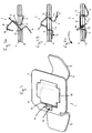
- a latch 1 has a first member 2 comprising a retaining lug 3 and a retaining portion 4. Formed in the retaining portion 4 is an aperture 5 through which a second member 6 can pass in use.
- the second member 6 has a retaining lug 7 and a retaining portion 8 which ensures that the second member 6 does not pass completely through the aperture 5 in use.
- the aperture 5 has a cut away portion 9 through which a release tool (not shown) can be inserted in use to gain access to a sprung barb 10 on the second member 6.
- the second member 6 is prevented from passing completely through the first member 2 by its retaining portion 8, and the sprung barb 10 passes through the aperture 5 and then moves to engage with the surface of the first member which is facing the aperture 13.
- the latch 1 is then in a closed position.
- a second sprung barb 14 locates the latch 1 in the aperture 13 by preventing movement of the elements 11, 12.
- a tool can be inserted in the recess portion 9 of the aperture 5 and pivoted in the direction of arrows shown in figure 2C.
- the sprung barb 10 is drawn out of engagement with the first member 2 and the first member 2 and second member 6 can be pivoted with respect to one another and the elements 11 and 12 to remove the latch 1.
- the retaining lug 3, 7 of the first and second members 2, 6 are formed so that they provide a sprung retention in order to absorb vibration.
Abstract
Description
Claims (6)
- A latch for latching two elements, the latch comprising:a first member arranged to pass, in use, partially through an aperture formed through the two elements and having a retaining portion for engaging a surface of one of the two elements in use, the first member having an aperture formed therein and a retaining lug for engaging a surface of the other of the two elements in use; anda second member arranged to pass through the aperture in the first latching member in use, the second member having a retaining portion for engaging a surface of the retaining portion of the first member, a retaining lug for engaging a surface of the other two elements in use, and a sprung barb for retaining the second member in the aperture in the first member when inserted therein to thereby hold the latch in a closed position.
- A latch according to claim 1, wherein the aperture in the first member is configured so that access to the sprung barb can be made via the aperture so that a tool can be inserted through the aperture in order to release the barb and remove the second member from the first member.
- A latch according to claim 1 or claim 2, wherein the retaining lugs on the first and second members are sprung.
- A latch according to any of claims 1 to 3, wherein a second sprung barb is provided on the second member.
- A latch according to any of claims 1 to 4, wherein the first and second members are formed from metal, such as sprung steel.
- A latch according to any of claims 1 to 5, wherein the first member has a second aperture through which a portion of the second member may pass in use.
Applications Claiming Priority (2)
| Application Number | Priority Date | Filing Date | Title |
|---|---|---|---|
| GB9821184 | 1998-09-30 | ||
| GBGB9821184.0A GB9821184D0 (en) | 1998-09-30 | 1998-09-30 | Latch |
Publications (2)
| Publication Number | Publication Date |
|---|---|
| EP0990803A1 true EP0990803A1 (en) | 2000-04-05 |
| EP0990803B1 EP0990803B1 (en) | 2003-07-16 |
Family
ID=10839670
Family Applications (1)
| Application Number | Title | Priority Date | Filing Date |
|---|---|---|---|
| EP19990307036 Expired - Lifetime EP0990803B1 (en) | 1998-09-30 | 1999-09-03 | Latch |
Country Status (3)
| Country | Link |
|---|---|
| EP (1) | EP0990803B1 (en) |
| DE (1) | DE69909568T2 (en) |
| GB (1) | GB9821184D0 (en) |
Cited By (2)
| Publication number | Priority date | Publication date | Assignee | Title |
|---|---|---|---|---|
| EP1561954A1 (en) * | 2004-02-05 | 2005-08-10 | Lisi Automotive Rapid | Connection element for a detachable connecting of partly overlapping parts as well as such a connection element in a housing and a procedure for detachable connecting of at least partly overlapping parts |
| FR2886986A1 (en) * | 2005-06-08 | 2006-12-15 | Renault Sas | Motor vehicle engine accessory support fastener comprises elastic clip with end tongue cut out to form shoulders engaging with lugs |
Citations (4)
| Publication number | Priority date | Publication date | Assignee | Title |
|---|---|---|---|---|
| GB598841A (en) * | 1944-10-28 | 1948-02-27 | United Carr Fastener Corp | Improvements in and relating to means for securing a fabric covering to an aperturedsupport |
| US3459094A (en) * | 1963-02-14 | 1969-08-05 | Tinnerman Products Inc | Fasteners |
| US4019764A (en) * | 1974-12-10 | 1977-04-26 | Matsushita Electric Industrial Co., Ltd. | Clamping device adapted to clamp plate-like members |
| US4745666A (en) * | 1987-07-17 | 1988-05-24 | Etco Building Systems, Inc. | Spring clip for sheet metal construction |
-
1998
- 1998-09-30 GB GBGB9821184.0A patent/GB9821184D0/en not_active Ceased
-
1999
- 1999-09-03 DE DE1999609568 patent/DE69909568T2/en not_active Expired - Fee Related
- 1999-09-03 EP EP19990307036 patent/EP0990803B1/en not_active Expired - Lifetime
Patent Citations (4)
| Publication number | Priority date | Publication date | Assignee | Title |
|---|---|---|---|---|
| GB598841A (en) * | 1944-10-28 | 1948-02-27 | United Carr Fastener Corp | Improvements in and relating to means for securing a fabric covering to an aperturedsupport |
| US3459094A (en) * | 1963-02-14 | 1969-08-05 | Tinnerman Products Inc | Fasteners |
| US4019764A (en) * | 1974-12-10 | 1977-04-26 | Matsushita Electric Industrial Co., Ltd. | Clamping device adapted to clamp plate-like members |
| US4745666A (en) * | 1987-07-17 | 1988-05-24 | Etco Building Systems, Inc. | Spring clip for sheet metal construction |
Cited By (2)
| Publication number | Priority date | Publication date | Assignee | Title |
|---|---|---|---|---|
| EP1561954A1 (en) * | 2004-02-05 | 2005-08-10 | Lisi Automotive Rapid | Connection element for a detachable connecting of partly overlapping parts as well as such a connection element in a housing and a procedure for detachable connecting of at least partly overlapping parts |
| FR2886986A1 (en) * | 2005-06-08 | 2006-12-15 | Renault Sas | Motor vehicle engine accessory support fastener comprises elastic clip with end tongue cut out to form shoulders engaging with lugs |
Also Published As
| Publication number | Publication date |
|---|---|
| DE69909568D1 (en) | 2003-08-21 |
| EP0990803B1 (en) | 2003-07-16 |
| GB9821184D0 (en) | 1998-11-25 |
| DE69909568T2 (en) | 2004-03-04 |
Similar Documents
| Publication | Publication Date | Title |
|---|---|---|
| US4708895A (en) | Plastic fastener | |
| US4669688A (en) | Cable clamp | |
| EP1373667B1 (en) | Push lock | |
| EP0795934A2 (en) | Connector provided with a retainer | |
| US4609119A (en) | Retaining device for mounting electrical units | |
| US6145173A (en) | Article attaching device | |
| EP0402822A3 (en) | Anti-theft case, particularly for compact disc cassettes, video cassettes, and the like | |
| EP0990803B1 (en) | Latch | |
| US5484175A (en) | Cabinet lock and method for using same | |
| US20080023361A1 (en) | Disk holding device | |
| JP4968779B2 (en) | Sealing tool | |
| US20110192065A1 (en) | Cover for inscription fields | |
| US6425706B1 (en) | Apparatus for fastening objects flush to a surface | |
| JP3706482B2 (en) | Electronic equipment casing | |
| US7103892B2 (en) | Screwless optical disc drive housing | |
| JP3226833B2 (en) | Lock structure between body and lid | |
| US5216206A (en) | Edge saddle with plural steps | |
| JP2008068485A (en) | Loose-leaf binder with lock | |
| EP0962664A1 (en) | Releasable fastening element | |
| JPH08107616A (en) | Locking structure of box with cover | |
| JPH11330713A (en) | Small case for containing electronic part | |
| JP3950917B2 (en) | Electrical component holder | |
| JP4276662B2 (en) | Automotive equipment | |
| JPH02310999A (en) | Rail mounting device for electric apparatus | |
| JPH1193932A (en) | Stud fixture and part mounting structure |
Legal Events
| Date | Code | Title | Description |
|---|---|---|---|
| PUAI | Public reference made under article 153(3) epc to a published international application that has entered the european phase |
Free format text: ORIGINAL CODE: 0009012 |
|
| AK | Designated contracting states |
Kind code of ref document: A1 Designated state(s): DE ES FR GB IT SE |
|
| AX | Request for extension of the european patent |
Free format text: AL;LT;LV;MK;RO;SI |
|
| 17P | Request for examination filed |
Effective date: 20000925 |
|
| AKX | Designation fees paid |
Free format text: DE ES FR GB IT SE |
|
| GRAH | Despatch of communication of intention to grant a patent |
Free format text: ORIGINAL CODE: EPIDOS IGRA |
|
| GRAH | Despatch of communication of intention to grant a patent |
Free format text: ORIGINAL CODE: EPIDOS IGRA |
|
| GRAA | (expected) grant |
Free format text: ORIGINAL CODE: 0009210 |
|
| AK | Designated contracting states |
Designated state(s): DE ES FR GB IT SE |
|
| PG25 | Lapsed in a contracting state [announced via postgrant information from national office to epo] |
Ref country code: IT Free format text: LAPSE BECAUSE OF FAILURE TO SUBMIT A TRANSLATION OF THE DESCRIPTION OR TO PAY THE FEE WITHIN THE PRESCRIBED TIME-LIMIT;WARNING: LAPSES OF ITALIAN PATENTS WITH EFFECTIVE DATE BEFORE 2007 MAY HAVE OCCURRED AT ANY TIME BEFORE 2007. THE CORRECT EFFECTIVE DATE MAY BE DIFFERENT FROM THE ONE RECORDED. Effective date: 20030716 |
|
| REG | Reference to a national code |
Ref country code: GB Ref legal event code: FG4D |
|
| REF | Corresponds to: |
Ref document number: 69909568 Country of ref document: DE Date of ref document: 20030821 Kind code of ref document: P |
|
| PG25 | Lapsed in a contracting state [announced via postgrant information from national office to epo] |
Ref country code: SE Free format text: LAPSE BECAUSE OF FAILURE TO SUBMIT A TRANSLATION OF THE DESCRIPTION OR TO PAY THE FEE WITHIN THE PRESCRIBED TIME-LIMIT Effective date: 20031016 |
|
| PG25 | Lapsed in a contracting state [announced via postgrant information from national office to epo] |
Ref country code: ES Free format text: LAPSE BECAUSE OF FAILURE TO SUBMIT A TRANSLATION OF THE DESCRIPTION OR TO PAY THE FEE WITHIN THE PRESCRIBED TIME-LIMIT Effective date: 20031027 |
|
| ET | Fr: translation filed | ||
| PLBE | No opposition filed within time limit |
Free format text: ORIGINAL CODE: 0009261 |
|
| STAA | Information on the status of an ep patent application or granted ep patent |
Free format text: STATUS: NO OPPOSITION FILED WITHIN TIME LIMIT |
|
| 26N | No opposition filed |
Effective date: 20040419 |
|
| PGFP | Annual fee paid to national office [announced via postgrant information from national office to epo] |
Ref country code: GB Payment date: 20040915 Year of fee payment: 6 |
|
| PGFP | Annual fee paid to national office [announced via postgrant information from national office to epo] |
Ref country code: DE Payment date: 20040916 Year of fee payment: 6 |
|
| PGFP | Annual fee paid to national office [announced via postgrant information from national office to epo] |
Ref country code: FR Payment date: 20040927 Year of fee payment: 6 |
|
| REG | Reference to a national code |
Ref country code: GB Ref legal event code: 732E |
|
| REG | Reference to a national code |
Ref country code: FR Ref legal event code: TP Ref country code: FR Ref legal event code: CD |
|
| PG25 | Lapsed in a contracting state [announced via postgrant information from national office to epo] |
Ref country code: GB Free format text: LAPSE BECAUSE OF NON-PAYMENT OF DUE FEES Effective date: 20050903 |
|
| PG25 | Lapsed in a contracting state [announced via postgrant information from national office to epo] |
Ref country code: DE Free format text: LAPSE BECAUSE OF NON-PAYMENT OF DUE FEES Effective date: 20060401 |
|
| GBPC | Gb: european patent ceased through non-payment of renewal fee |
Effective date: 20050903 |
|
| PG25 | Lapsed in a contracting state [announced via postgrant information from national office to epo] |
Ref country code: FR Free format text: LAPSE BECAUSE OF NON-PAYMENT OF DUE FEES Effective date: 20060531 |
|
| REG | Reference to a national code |
Ref country code: FR Ref legal event code: ST Effective date: 20060531 |