EP0990488A2 - Power driven screwdriver - Google Patents
Power driven screwdriver Download PDFInfo
- Publication number
- EP0990488A2 EP0990488A2 EP99115724A EP99115724A EP0990488A2 EP 0990488 A2 EP0990488 A2 EP 0990488A2 EP 99115724 A EP99115724 A EP 99115724A EP 99115724 A EP99115724 A EP 99115724A EP 0990488 A2 EP0990488 A2 EP 0990488A2
- Authority
- EP
- European Patent Office
- Prior art keywords
- drive shaft
- ring
- cam
- elements
- tool
- Prior art date
- Legal status (The legal status is an assumption and is not a legal conclusion. Google has not performed a legal analysis and makes no representation as to the accuracy of the status listed.)
- Granted
Links
Images


Classifications
-
- B—PERFORMING OPERATIONS; TRANSPORTING
- B25—HAND TOOLS; PORTABLE POWER-DRIVEN TOOLS; MANIPULATORS
- B25B—TOOLS OR BENCH DEVICES NOT OTHERWISE PROVIDED FOR, FOR FASTENING, CONNECTING, DISENGAGING OR HOLDING
- B25B23/00—Details of, or accessories for, spanners, wrenches, screwdrivers
- B25B23/0064—Means for adjusting screwing depth
-
- B—PERFORMING OPERATIONS; TRANSPORTING
- B25—HAND TOOLS; PORTABLE POWER-DRIVEN TOOLS; MANIPULATORS
- B25B—TOOLS OR BENCH DEVICES NOT OTHERWISE PROVIDED FOR, FOR FASTENING, CONNECTING, DISENGAGING OR HOLDING
- B25B23/00—Details of, or accessories for, spanners, wrenches, screwdrivers
- B25B23/14—Arrangement of torque limiters or torque indicators in wrenches or screwdrivers
- B25B23/141—Mechanical overload release couplings
Abstract
Description
Die Erfindung betrifft einen kraftgetriebenen Schrauber umfassend:
- ein Gehäuse, an dem ein Tiefenanschlag festlegbar ist,
- ein relativ zum Tiefenanschlag in Richtung ihrer Drehachse verschiebbare Werkzeugantriebswelle, an der eine Werkzeugaufnahme gehalten ist,
- eine Antriebswelle,
- ein auf der Antriebswelle drehbar und axial verschieblich aufgenommenes Antriebsrad, das motorisch angetrieben ist,
- einen Zwischenring, der auf der Antriebswelle drehbar gelagert ist und eine erste, dem Antriebsrad zugewandte Seite und eine zweite Seite aufweist,
- einen Nockenring, der auf der Werkzeugantriebswelle drehbar gelagert ist und eine erste, dem Zwischenring zugewandte und eine zweite Seite aufweist,
- erste Nockenelemente auf dem Antriebsrad, die mit zugeordneten zweiten Nockenelementen auf der ersten Seite des Zwischenrings zusammenwirken, um eine erste Nockenkupplung zu bilden,
- dritte Nockenelemente auf der zweiten Seite des Zwischenrings, die mit zugeordneten Nockenelementen auf dem Nockenring zusammenwirken, um eine zweite Nockenkupplung zu bilden,
- erste Mitnahmeelemente am Zwischenring, die mit zugeordneten zweiten Mitnahmeelementen am Nockenring zusammenwirken und gemeinsam mit den dritten und vierten Nockenelementen eine Mitnahmekupplung bilden und
- ein erstes Federelement zur geräuschlosen Trennung beim Auslösen der Auslösekupplung.
- a housing to which a depth stop can be fixed,
- a tool drive shaft which can be displaced relative to the depth stop in the direction of its axis of rotation and on which a tool holder is held,
- a drive shaft,
- a drive wheel which is rotatably and axially displaceably received on the drive shaft and is motor-driven,
- an intermediate ring which is rotatably mounted on the drive shaft and has a first side facing the drive wheel and a second side,
- a cam ring which is rotatably mounted on the tool drive shaft and has a first side facing the intermediate ring and a second side,
- first cam elements on the drive wheel which cooperate with associated second cam elements on the first side of the intermediate ring to form a first cam clutch,
- third cam elements on the second side of the intermediate ring, which interact with associated cam elements on the cam ring to form a second cam clutch,
- first driver elements on the intermediate ring, which interact with assigned second driver elements on the cam ring and together with the third and fourth cam elements form a driver clutch and
- a first spring element for noiseless separation when the release clutch is triggered.
Ein derartiger Schrauber mit Tiefenanschlag ist aus der US 4 655 103 bekannt.Such a screwdriver with depth stop is from the US 4,655,103.
Mit dem bekannten Schrauber läßt sich eine Schraube auf eine mit einem Tiefenanschlag voreingestellte Einschraubtiefe in eine Oberfläche einschrauben. Wenn der Tiefenanschlag auf die Oberfläche aufläuft, wird die Abschaltung einer Kupplung eingeleitet, mit der eine weitgehend geräuschlose Abschaltung erfolgt. Hierzu ist ein motorisch angetriebenes Antriebsrad vorgesehen, das mit einem axial beweglich angeordneten Zwischenrad eine erste Nockenkupplung bildet. Das Zwischenrad wirkt auf seiner anderen, dem Werkzeugträger zugewandten Seite mit einem weiteren Kupplungselement zusammen, wobei die schrägen Nockenflächen der zugeordneten Elemente eine zweite Nockenkupplung bilden. Zusätzlich sind am Zwischenrad und an dem zweiten Kupplungselement Mitnahmeelemente in Form von geraden achsparallelen Flanken vorgesehen, durch die bei Auftreten eines gewissen Grundnoments das mit der Werkzeugaufnahme verbundenen Kupplungselement vom Zwischenkupplungselement mitgenommen wird. Zusätzlich ist zwischen dem Antriebsrad und dem Zwischenrad eine Druckteder angeordnet, durch die das Zwischenrad in Richtung auf die Werkzeugaufnahme vorgespannt wird.With the known screwdriver, a screw can be placed on a with a depth stop preset screwing depth in screw in a surface. If the depth stop on the Surface closes, a clutch is switched off, with a largely silent shutdown. For this purpose, a motor-driven drive wheel is provided, that with an axially movable intermediate wheel forms a first cam clutch. The intermediate wheel acts on its other side facing the tool carrier with one another coupling element together, the oblique cam surfaces the assigned elements a second cam clutch form. In addition are on the idler gear and on the second coupling element Driving elements in the form of straight axially parallel Flanks provided by which when a certain basic notion associated with the tool holder Coupling element is taken from the intermediate coupling element. In addition, there is between the drive wheel and the intermediate wheel a Druckteder arranged through which the idler gear in the direction is preloaded on the tool holder.
Im Betrieb wird zunächst der Tiefenanschlag auf die gewünschte Einschraubtiefe eingestellt und dann der Werkzeugträger mit seinem Werkzeug auf eine etwa einzudrehende Schraube aufgesetzt und angedrückt. Hierdurch gelangen alle drei Kupplungselemente miteinander in Eingriff, so daß zunächst das Drehmoment vom Antriebsrad auf den Werkzeugträger übertragen wird, wenn mit dem Einschraubvorgang begonnen wird. Durch das auftretende Drehmoment während des Schraubvorgangs werden das Zwischenrad und das mit der Werkzeugaufnahme verbundene Kupplungselement etwas auseinandergedrückt, bis die geraden Mitnahmeflanken miteinander in Eingriff gelangen und eine formschlüssige Mitnahme gewährleistet ist. Läuft der Tiefenanschlag auf der Oberfläche auf, so bewegt sich der Werkzeugträger mit der Werkzeugaufnahme und der Schraube noch weiter, bis diese vollständig eingeschraubt ist. Dann gleiten die Nockenelemente der ersten Nockenkupplung mit Unterstützung der Druckfeder auseinander, bis diese auslöst. Infolge des nunmehr auf null abgefallenen Drehmomentes wird das Zwischenrad durch die Druckfeder an das zweite mit der Werkzeugaufnahme verbundene Kupplungselement angedrückt, so daß sich das Antriebsrad frei weiterdrehen kann, ohne das Zwischenrad zu berühren. Es erfolgt somit eine "geräuschlose" Abschaltung.In operation, the depth stop is first set to the desired one Screw-in depth set and then the tool holder with his tool placed on a screw to be screwed in and pressed. This will get all three coupling elements with each other so that the torque from the drive wheel is transferred to the tool carrier if with the Screwing process is started. Due to the occurring torque the idler gear and the coupling element connected to the tool holder somewhat pushed apart until the straight drive flanks join together come into engagement and a form-fit entrainment guaranteed is. The depth stop runs on the surface the tool carrier moves with the tool holder and the screw further until this is complete is screwed in. Then the cam elements of the first slide Apart with the support of the compression spring, until it triggers As a result of the now dropped to zero The idler gear is connected to the torque by the compression spring pressed on second coupling element connected to the tool holder, so that the drive wheel can turn freely, without touching the idler. There is thus a "noiseless" Shutdown.
Darüber hinaus sind verschiedene Schrauber bekannt, mit denen
eine Trennung des Antriebsstrangs von einer Abschaltung erfolgen
kann, sobald ein voreingestelltes Drehmoment erreicht
ist (vergl. z.B. EP 0 239 670 B1).In addition, various screwdrivers are known with which
the drive train is disconnected from a shutdown
can, as soon as a preset torque is reached
(see
Darüber hinaus ist es bekannt, bei einer Schraub-Werkzeugmaschine
eine Umschaltmöglichkeit zwischen einer Abschaltung
über Tiefenanschlag und einer Abschaltung über ein voreingestelltes
Drehmoment wahlweise vorzunehmen (EP 0 401 548 B1).
Wird dieser Schrauber zur Abschaltung mit Tiefenanschlag benutzt,
so entsprechen Aufbau und Funktionsweise prinzipiell der
zuvor erwähnten US 4 655 103.In addition, it is known in a screw machine tool
a switchover option between a shutdown
via depth stop and a shutdown via a preset
Torque to choose from (
Durch einen über Stifte beim Abnehmen des Tiefenanschlags aktivierten, federbeaufschlagten Überwurfring, der den Zwischenring und das zweite, der Werkzeugantriebswelle zugewandte Kupplungselement überdeckt, werden das Zwischenkupplungselement und das zweite Kupplungselement bei abgenommenem Tiefenanschlag unter Wirkung der Feder aufeinander gedrückt und über eine Keilverzahnung miteinander formschlüssig verbunden, so daß diese beiden Elemente auch bei Drehmomentbeaufschlagung wie ein einziges Kupplungselement wirken. In dieser Stellung ergibt sich somit in Verbindung mit den schrägen Nockenflächen des Antriebszahnrades eine Nockenkupplung, die bei einem über einen entsprechenden Verstellmechanismus voreingestellten Drehmoment auslöst. Activated via pins when removing the depth stop, spring-loaded collar ring, the intermediate ring and the second coupling element facing the tool drive shaft covered, the intermediate coupling element and the second coupling element with the depth stop removed pressed together under the action of the spring and over a Splines are positively connected so that these two elements even when torque is applied act only coupling element. In this position results thus in connection with the oblique cam surfaces of the drive gear a cam clutch, which one over one corresponding adjustment mechanism preset torque triggers.
Allerdings läuft diese Kupplung auch nach dem Auslösen ratternd weiter.However, this clutch rattles even after it has been triggered further.
Der Erfindung liegt somit die Aufgabe zugrunde, einen verbesserten kraftgetriebenen Schrauber mit Tiefenanschlag zu schaffen, bei dem wahlweise entweder eine Abschaltung über Tiefenanschlag oder aber eine drehmomentabhängige Abschaltung ermöglicht wird und in beiden Fällen kein Rattern der Abschaltkupplung auftritt.The invention is therefore based on the object of an improved power screwdriver with depth stop too create, either with a shutdown via depth stop or allows a torque-dependent shutdown and in both cases no rattling of the Shutdown clutch occurs.
Diese Aufgabe wird erfindungsgemäß bei einem Schrauber gemäß der eingangs genannten Art dadurch gelöst, daß
- ein Ausrückring vorgesehen ist, der auf der Werkzeugantriebswelle gegen einen Widerstand gelagert ist,
- das erste Federelement zwischen dem Nockenring und dem Ausrückring angeordnet ist, um den Nockenring in Richtung auf das Antriebsrad vorzuspannen,
- auf der den ersten Nockenelementen abgewandten Seite des Antriebsrades ein zweites gehäuseseitig abgestütztes Federelement vorgesehen ist,
- erste Klauenelemente an der zweiten Seite des Nockenrings vorgesehen sind, die mit zweiten Klauenelementen am Ausrückring zusammenwirken, um eine Trennkupplung zu bilden.
- a release ring is provided which is mounted on the tool drive shaft against resistance,
- the first spring element is arranged between the cam ring and the release ring in order to prestress the cam ring in the direction of the drive wheel,
- a second spring element supported on the housing side is provided on the side of the drive wheel facing away from the first cam elements,
- first claw elements are provided on the second side of the cam ring, which cooperate with second claw elements on the disengaging ring to form a separating clutch.
Die Aufgabe der Erfindung wird auf diese Weise vollkommen gelöst.The object of the invention is completely achieved in this way.
Sowohl bei der Verwendung eines Tiefenanschlags als auch bei abgenommenem Tiefenanschlag erfolgt bei Beendigung eines Schraubvorgangs eine Trennung der Antriebswelle von der Werkzeugantriebswelle, wobei sichergestellt ist, daß auch bei einem Weiterlaufen des Antriebsmotors kein Rattern auftritt.Both when using a depth stop and when removed depth stop takes place at the end of a A separation of the drive shaft from the tool drive shaft, whereby it is ensured that even with a If the drive motor continues to run, no rattling occurs.
In bevorzugter Weiterbildung der Erfindung ist der Ausrückring auf der Werkzeugantriebswelle verdrehgesichert und gegen den Widerstand axial verschiebbar festgelegt. Ferner ist eine Sperreinrichtung vorgesehen, um den Ausrückring in einer axial in Richtung auf die Werkzeugaufnahme vorgeschobenen Position zu halten, wenn sich der Ausrückring im Betrieb unter Last axial in Richtung auf die Werkzeugaufnahme verschiebt, und um den Ausrückring nach einem Auslösen der Trennkupplung und anschließender Entlastung wieder freizugeben.In a preferred development of the invention, the release ring is on the tool drive shaft secured against rotation and against the Resistance axially displaceable. Furthermore, one Locking device provided to the release ring in an axial advanced towards the tool holder hold when the release ring is axially in operation under load moves towards the tool holder, and around the Release ring after the disconnect clutch has tripped and then Relieve discharge again.
Gemäß einer Weiterbildung der Erfindung ist an der Werkzeugantriebswelle ein Axialanschlag vorgesehen, an dem sich ein drittes Federelement abstützt, gegen das der Ausrückring axial in Richtung auf die Werkzeugaufnahme verschiebbar ist.According to a development of the invention is on the tool drive shaft an axial stop is provided, on which a supports third spring element against which the disengagement ring axially is displaceable in the direction of the tool holder.
Durch eine solche Anordnung eines Federelementes kann die Freigabe der in vorgeschobener Position verriegelten Sperreinrichtung nach einem Auslösen und nach anschließender Entlastung der Trennkupplung auf einfache Weise erreicht werden.Such an arrangement of a spring element enables the release the locking device locked in the advanced position after triggering and after subsequent relief of the Isolation clutch can be achieved in a simple manner.
Gemäß einer weiteren Ausführung der Erfindung ist das erste Federelement zwischen dem Nockenring und einem Axialanschlag der Werkzeugantriebswelle eingespannt.According to a further embodiment of the invention, the first is Spring element between the cam ring and an axial stop the tool drive shaft clamped.
Durch eine derartige Anordnung des ersten Federelementes wird die Funktion der Mitnahmekupplung unterstützt. Such an arrangement of the first spring element supports the function of the driving clutch.
In weiter bevorzugter Ausgestaltung der Erfindung ist die Werkzeugantriebswelle mit einem Ende an der Antriebswelle axial verschieblich geführt.In a further preferred embodiment of the invention, the tool drive shaft with one end axially on the drive shaft slidably guided.
Auf diese Weise wird die Lagerung der Werkzeugantriebswelle vereinfacht.In this way, the bearing of the tool drive shaft simplified.
In bevorzugter Weiterbildung der Erfindung ist die Verriegelungseinrichtung als Kugelgesperre ausgebildet, das durch ein viertes Federelement verriegelbar ist, das zwischen der Werkzeugantriebswelle und der Antriebswelle angeordnet ist.In a preferred development of the invention, the locking device is trained as a ball ratchet by a fourth spring element can be locked, which between the Tool drive shaft and the drive shaft is arranged.
Auf diese Weise kann die Relativbewegung zwischen Werkzeugantriebswelle und Antriebswelle dazu ausgenutzt werden, den Ausrückring auf einfache Weise in einer axial in Richtung auf die Werkzeugaufnahme vorgeschobenen Position zu arretieren.In this way, the relative movement between the tool drive shaft and drive shaft can be used to Release ring in a simple manner in an axial direction to lock the tool holder in the advanced position.
In zusätzlicher Weiterbildung dieser Ausführung weist die Verriegelungseinrichtung axiale Führungsstege an der Werkzeugantriebswelle auf, die mit zugeordneten Nuten am Ausrückring zur Führung desselben zusammenwirken.In an additional development of this embodiment, the locking device has axial guide webs on the tool drive shaft on that with assigned grooves on the release ring cooperate to guide it.
In zusätzlicher Weiterbildung dieser Ausführung sind die axialen Führungsstege als von der Werkzeugantriebswelle nach außen hervorstehende Stege ausgebildet, deren erstes werkzeugseitiges axiales Ende zur Abstützung des dritten Federelementes auf seiner dem Ausrückring zugewandten Seite dient, und deren zweites, dem Ausrückring zugewandtes Ende zur Abstützung des ersten Federelementes dient. In an additional development of this version are axial guide webs as from the tool drive shaft protruding webs formed on the outside, the first tool-side axial end for supporting the third spring element serves on its side facing the release ring, and their second end facing the release ring for supporting the serves the first spring element.
Auf diese Weise läßt sich der Aufbau und die Montage der Verriegelungseinrichtung und der zugehörigen Federelemente an der Werkzeugantriebswelle vereinfachen.In this way, the construction and assembly of the locking device and the associated spring elements on the Simplify tool drive shaft.
Hierbei ist bevorzugt, eine Mehrzahl von Kugeln in Querbohrungen der Werkzeugantriebswelle beweglich zu führen, die über eine zentrale Kugel durch das vierte Federelement zur Verriegelung des Ausrückrings beaufschlagbar sind.It is preferred here to have a plurality of balls in transverse bores the tool drive shaft to move the via a central ball through the fourth spring element Locking the release ring can be acted upon.
In zusätzlicher Weiterbildung dieser Ausführung weist die Werkzeugsantriebswelle auf der Seite der Antriebswelle eine zentrale Bohrung auf, in der die Antriebswelle mit einem ersten Ende axial verschieblich geführt ist.In an additional development of this embodiment, the tool drive shaft a central one on the side of the drive shaft Hole in which the drive shaft with a first End is axially displaceable.
Hierbei kann am ersten Ende der Antriebswelle eine Sacklochbohrung vorgesehen sein, in der ein erstes Ende des vierten Federelementes aufgenommen ist, wobei ein zweites Ende des vierten Federelementes am der zentralen Kugel anliegt, die in der Bohrung axial verschieblich geführt ist.Here, a blind hole can be made at the first end of the drive shaft be provided in which a first end of the fourth Spring element is added, with a second end of the fourth spring element abuts the central ball, which in the bore is guided axially.
Durch diese Maßnahmen ist eine sichere Funktion der Verriegelungseinrichtung gewährleistet und gleichzeitig ein vereinfachter Aufbau sichergestellt.These measures ensure that the locking device functions reliably guaranteed and at the same time a simplified Construction ensured.
Das zweite Federelement ist in zusätzlicher Weiterbildung der Erfindung als Tellerfeder ausgebildet, die sich zwischen dem Antriebsrad und einem Axialanschlag auf der der Werkzeugaufnahme abgewandten Seite des Antriebsrades abstützt.In an additional development, the second spring element is the Invention formed as a plate spring, which is between the Drive wheel and an axial stop on the tool holder supported side of the drive wheel.
Durch eine Ausbildung des zweiten Federelements als Tellerfeder läßt sich eine relativ hohe Federkraft bei einer geringen Baugröße des Federelements erreichen, um so einen großen Verstellbereich für das Auslösemoment bei Drehmomentabschaltung zu gewährleisten.By designing the second spring element as a plate spring can be a relatively high spring force with a small size of the spring element so as to achieve a large adjustment range to ensure the tripping torque when torque is switched off.
Der Tiefenanschlag ist in bevorzugter Weiterbildung der Erfindung am Gehäuse abnehmbar befestigt.The depth stop is in a preferred development of the invention detachably attached to the housing.
Obwohl der Tiefenanschlag auch auf andere Weise außer Funktion gesetzt werden könnte, ist dies eine besonders einfache Möglichkeit, um eine Umschaltung zwischen Abschaltung durch Tiefenanschlag und Drehmomentabschaltung zu ermöglichen.Although the depth stop is otherwise inoperative could be put, this is a particularly easy way to toggle between shutdown by Allow depth stop and torque shutdown.
In zusätzlicher Weiterbildung der Erfindung ist eine Steilhülse zur axialen Verstellung des Zwischenrings in Richtung auf das Antriebsrad vorgesehen.In an additional development of the invention is a steep sleeve for the axial adjustment of the intermediate ring in the direction of the Drive wheel provided.
Auf diese Weise kann durch Veränderung der Überdeckung zwischen den Nockenelementen des Zwischenrings und des Antriebsrads das Auslösemoment der Auslösekupplung auf einfache Weise verändert werden.This way, by changing the coverage between the cam elements of the intermediate ring and the drive wheel Tripping torque of the release clutch changed in a simple way become.
Hierzu ist in zusätzlicher Weiterbildung dieser Ausführung an der Stellhülse ein Rastring axial verschiebbar und gegenüber dieser verdrehgesichert festgelegt, der gegenüber dem Gehäuse verdrehbar und in verschiedenen Winkelpositionen verrastbar festgelegt ist.This is a further development of this version the adjusting sleeve axially displaceable and opposite this fixed against rotation, the opposite of the housing rotatable and lockable in different angular positions is set.
Auf diese Weise läßt sich eine einfache axiale Verstellung der Stellhülse in Bezug auf das Gehäuse zusammen mit einer Verrastung in verschiedenen Winkelpositionen auf einfache Weise erreichen, sofern die Steilhülse über ein Gewinde mit dem Gehäuse verbunden ist.In this way, a simple axial adjustment of the Adjusting sleeve in relation to the housing together with a latch in different angular positions in a simple way if the steep sleeve has a thread with the housing connected is.
Die Mitnahmeelemente am Nockenring und am Zwischenring sind in bevorzugter Weiterbildung der Erfindung als gerade, in Axialrichtung verlaufende Flanken am äußeren Ende der dritten und vierten Nockenelemente ausgebildet.The driving elements on the cam ring and on the intermediate ring are in preferred development of the invention as straight, in the axial direction running flanks at the outer end of the third and fourth cam elements formed.
Auf diese Weise läßt sich mit einfachen Mitteln eine formschlüssige Mitnahme zur Kraftübertragung vom Zwischenring auf den Nockenring erreichen. Grundsätzlich wären allerdings auch andere Verbindungen denkbar, beispielsweise die Verwendung von gekrümmten Oberflächen an einem der beiden Ringe, an denen beispielsweise ein Querstift am anderen der beiden Ringe geführt ist.In this way, a positive fit can be achieved with simple means Driving for power transmission from the intermediate ring reach the cam ring. Basically, however, would also be other connections conceivable, for example the use of curved surfaces on one of the two rings, on which, for example a cross pin on the other of the two rings is.
In zweckmäßiger Weiterbildung der Erfindung sind die Federelemente so aufeinander abgestimmt, daß die Verriegelungseinrichtung nach einer Abschaltung des Schraubers und anschließenden Entlastung wieder entriegelt und in ihre Ausgangslage zurückgeschoben wird.In an expedient development of the invention, the spring elements matched so that the locking device after switching off the screwdriver and subsequent Relief unlocked again and in their starting position is pushed back.
In weiterer Ausgestaltung der Erfindung sind ferner die ersten und zweiten Klauenelemente als Klauen mit geraden, in Axialrichtung verlaufenden Flächen oder als Nocken mit schrägen Flächen ausgebildet, die steiler in Bezug auf die Axialrichtung geneigt sind als die ersten bis vierten Nockenelemente.In a further embodiment of the invention, the first are also and second claw elements as claws with straight, in the axial direction running surfaces or as cams with oblique Surfaces formed that are steeper in relation to the axial direction are inclined as the first to fourth cam members.
Diese Maßnahmen ermöglichen eine einfache Ausgestaltung und Herstellung der betreffenden Nockenelemente, Mitnahmeelemente und Klauenelemente. These measures allow a simple design and Production of the relevant cam elements, driving elements and claw elements.
In weiterer Ausgestaltung der Erfindung sind die ersten, zweiten, dritten und vierten Nockenelemente als schräge Nockenflächen ausgebildet, wobei die Steigung der ersten und zweiten Nockenelemente größer ist als die Steigung der dritten und vierten Nockenelemente, um unter Last zu gewährleisten, daß sich zunächst der Nockenring in Richtung auf den Ausrückring verschiebt, bevor bei erhöhtem Drehmoment eine Verschiebung des Antriebsrades auftritt.In a further embodiment of the invention, the first, second, third and fourth cam elements as oblique cam surfaces formed, the slope of the first and second Cam elements is greater than the slope of the third and fourth cam elements to ensure that under load first the cam ring in the direction of the release ring shifts before a shift of the Drive wheel occurs.
Bei einer derartigen Ausgestaltung ist eine sichere Funktion in Verbindung mit einfacher Herstellung und Montage erreichbar.With such a configuration, a reliable function is in Connection can be achieved with simple manufacture and assembly.
Es versteht sich, daß die vorstehend genannten und die nachstehend noch zu erläuternden Merkmale der Erfindung nicht nur in der jeweils angegebenen Kombination, sondern auch in anderen Kombinationen oder in Alleinstellung verwendbar sind, ohne den Rahmen der Erfindung zu verlassen.It is understood that the above and those below Features of the invention not yet to be explained in the specified combination, but also in others Combinations or alone can be used without the Leave the scope of the invention.
Weitere Merkmale und Vorteile der Erfindung ergeben sich aus der nachfolgenden Beschreibung bevorzugter Ausführungsbeispiele unter Bezugnahme auf die Zeichnung. Es zeigen:
- Fig. 1
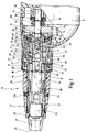
- einen Längs-Teilschnitt durch einen erfindungsgemäßen Schrauber;
- Fig. 2a - 2d
- Prinzipdarstellungen zur Funktion des erfindungsgemäßen Schraubers bei Verwendung der Drehmomentabschaltung in stark vereinfachter Darstellungsweise, wobei Fig. 2a das manuelle Ansetzen und Andrücken des Schraubers auf eine Schraube zeigt,
- Fig. 2b
- die sich während des Einschraubvorgangs infolge eines gewissen Grunddrehmoments einstellende Stellung zeigt,
- Fig. 2c
- die Auslösung der Auslösekupplung bei Erreichen des voreingestellten Drehmoments zeigt,
- Fig. 2d
- die infolge des abgefallenen Drehmoments erfolgende Auslösung der Trennkupplung zeigt, wodurch ein ratterfreies Weiterlaufen ermöglicht wird;
- Fig. 3a - 3d
- Prinzipdarstellungen des erfindungsgemäßen Schraubers bei Verwendung des Tiefenanschlags in stark vereinfachter Darstellung zeigen, wobei
- Fig. 3a
- das Ansetzen des Schraubers an einer Schraube zeigt,
- Fig. 3b
- die sich während des Schraubvorgangs infolge des Grunddrehmoments einstellende Stellung zeigt,
- Fig. 3c
- das Auflaufen des Tiefenanschlags auf die Oberfläche zeigt, in der die Schraube eingedreht wird und
- Fig. 3d
- das Ansprechen der Trennkupplung zeigt, wodurch ein ratterfreies Weiterlaufen ermöglicht wird.
- Fig. 1
- a partial longitudinal section through a screwdriver according to the invention;
- 2a-2d
- Basic representations of the function of the screwdriver according to the invention when using the torque cut-off in a greatly simplified representation, FIG. 2a showing the manual attachment and pressing of the screwdriver onto a screw,
- Fig. 2b
- the position that appears during the screwing-in process as a result of a certain basic torque,
- Fig. 2c
- shows the release of the release clutch when the preset torque is reached,
- Fig. 2d
- shows the release of the separating clutch as a result of the drop in torque, which enables chatter-free operation;
- 3a-3d
- Show schematic diagrams of the screwdriver according to the invention when using the depth stop in a highly simplified representation, wherein
- Fig. 3a
- shows the attachment of the screwdriver to a screw,
- Fig. 3b
- the position which arises during the screwing operation due to the basic torque,
- Fig. 3c
- shows the impact of the depth stop on the surface in which the screw is screwed in and
- Fig. 3d
- shows the response of the disconnect clutch, which enables a chatter-free continued operation.
In Fig. 1 ist ein erfindungsgemäßer Schrauber insgesamt mit der
Ziffer 10 bezeichnet.In Fig. 1, a screwdriver according to the invention is overall with the
Der Schrauber 10 umfaßt ein Gehäuse 11, in dem ein Motor (nicht
dargestellt) aufgenommen ist, der über ein Zahnrad 74 ein damit
kämmendes Antriebsrad 72 antreibt. Weitere Teile des so
gebildeten Getriebes sind nicht dargestellt. Das Antriebsrad 72
ist auf einer Antriebswelle 70 gelagert, die mit einer
Werkzeugantriebswelle 30 fluchtet, an deren äußerem Ende eine
Werkzeugaufnahme 26, beispielsweise zur Aufnahme eines
Schraubendreher-Bits vorgesehen ist.The
Das Drehmoment vom Antriebsrad 72 kann über einen Zwischenring
55 und einen Nockenring 50 auf einen Ausrückring 36 übertragen
werden, der verdrehgesichert und axial verschiebbar auf der
Werkzeugantriebswelle 30 festgelegt ist.The torque from the
Die Werkzeugantriebswelle 30 ist in Richtung ihrer Drehachse 27
in Bezug auf die Antriebswelle 70 verschiebbar. Hierzu ist am
der Antriebswelle 70 zugewandten Ende der Werkzeugantriebswelle
30 eine zentrale Bohrung 41 vorgesehen, mit der die Werkzeugantriebswelle
30 auf dem Ende der Antriebswelle 70 axial verschieblich
geführt ist.The
Der Zwischenring 55 ist auf der Werkzeugantriebswelle 30 und
der Antriebswelle 70 frei drehbar gelagert. Der Nockenring 50
ist zwischen dem Zwischenring 55 und dem Ausrückring 36 gleichfalls
frei drehbar auf der Werkzeugantriebswelle 30 angeordnet.
Dagegen ist der Ausrückring 36 auf axialen Führungsstegen 33 an
der Außenseite der Werkzeugantriebswelle 30, die als Außenstege
nach Art eines Keilprofils ausgebildet sind, die in entsprechend
geformte Nuten am Ausrückring 36 eingreifen, axial
verschiebbar, jedoch drehfest gelagert. Am Antriebsrad 72 sind
auf der dem Zwischenring 55 zugewandten Seite Nockenelemente 61
mit schrägen Nocken gemäß der aus der US 4 655 103 bekannten
Art angeordnet. In diese ersten Nockenelemente 61 greifen entsprechend
geformte zweite Nockenelemente 57 ein, die am
Zwischenring 55 vorgesehen sind. Durch diese ineinandergreifenden
schrägen Nockenflanken ist somit eine Auslösekupplung
gebildet, die insgesamt mit der Ziffer 62 bezeichnet
ist.The
Das Antriebsrad 72 ist durch einen Sicherungsring 71 in Richtung
auf die Werkzeugaufnahme 26 gesichert und auf der anderen
Seite durch ein Federelement 46 in Form einer Tellerfeder, das
im folgenden als zweites Federelement bezeichnet wird, vorgespannt.
Die Tellerfeder ist gleichfalls durch einen Sicherungsring
75 gesichert und wird am dem Antriebsrad 72 abgewandten
Ende von einem Axiallager 76 abgestützt, das am Gehäuse 11 aufgenommen
ist. Die Antriebswelle 70 ist mit diesem Ende ferner
in einem Radiallager 77, das als Gleitlager ausgeführt sein
kann, im Gehäuse 11 gelagert.The
Der Zwischenring 55 bildet zusammen mit dem Nockenring 50 eine
Mitnahmekupplung, die insgesamt mit der Ziffer 65 bezeichnet
ist. Die Mitnahmekupplung 65 weist dritte Nockenelemente 56 in
Form von schrägen Nockenflächen auf, denen vierte Nockenelemente
52 entsprechender Form am Nockenring 50 zugeordnet
sind. Am dem jeweils anderen Teil zugeordneten Ende dieser
schrägen Nockenflächen sind Mitnahmeelemente 100 und 101 vorgesehen,
deren Form aus den Figuren 2a bis 2d ersichtlich ist. Es
handelt sich um erste Mitnahmeelemente 100 in Form von geraden,
achsparallelen Flanken am äußeren Ende der schrägen Nockenelemente
56 am Zwischenring und um entsprechende Mitnahmeelemente
101 in Form von geraden Flanken am Ende der schrägen
Nockenelemente 52 des Nockenrings 50.The
Auf diese Weise wird durch die Nockenelemente 52, 56 und die
Mitnahmeelemente 100, 101 die Mitnahmekupplung 65 gebildet,
durch die der Nockenring 50 vom Zwischenring 55 mitgenommen
wird, wobei sich bei Auftreten eines gewissen Grunddrehmomentes
eine axiale Verschiebung einstellt, bis die Mitnahmeelemente
100, 101 formschlüssig ineinander greifen.In this way, the
Zwischen dem Nockenring 50 und dem Ausrückring 36 ist ferner
eine insgesamt mit der Ziffer 54 bezeichnete Trennkupplung gebildet,
die aus ersten Klauenelementen 51 mit geraden,
achsparallelen Flanken am Nockenring 50 und aus zweiten
Klauenelementen 37 mit entsprechend geformten, geraden Flanken
am Ausrückring 36 besteht.There is also between the
Die axialen Führungsstege 33 an der Werkzeugantriebswelle 30
weisen ein erstes, werkzeugseitiges Ende 34 und ein zweites,
dem Antriebsrad 72 zugewandtes Ende 35 auf. Zwischen dem zweiten
Ende 35 und dem Nockenring 50 ist ein erstes Federelement
45 in Form einer die Werkzeugantriebswelle 30 umschließenden
Spiralfeder angeordnet, die die Werkzeugantriebswelle 30 in
eine vom Nockenring 50 abgewandte Richtung vorspannt. Das
zweite Federelement 46 in Form der Tellerfeder ist - wie
bereits erwähnt - zwischen dem Antriebsrad 72 und einem
Radiallager 76 angeordnet.The
Ein drittes Federelement 47, das gleichfalls als die
Werkzeugantriebswelle umschließende Spiralfeder ausgebildet
ist, ist zwischen dem ersten werkzeugseitigen Ende 34 der
axialen Führungsstege 33 und dem Axialanschlag 31 eingespannt,
um den Ausrückring 36 in Richtung auf das Antriebsrad 72
vorzuspannen. A
Der Ausrückring 36 kann durch eine Sperreinrichtung, die insgesamt
mit der Ziffer 43 bezeichnet ist, in einer entgegen der
Kraft des dritten Federelementes 47 in Richtung auf die Werkzeugaufnahme
26 vorgeschobenen Position verriegelt werden, so
daß ein Zurückgleiten des Ausrückrings 36 in Richtung auf das
Antriebsrad 72 verhindert ist. Diese Sperreinrichtung 43 ist
als Kugelgesperre ausgebildet, das insgesamt drei kleine Kugeln
39 aufweist, die in Querbohrungen der Werkzeugantriebswelle 30
in Radialrichtung geführt sind, sowie eine zentrale große Kugel
40 aufweist, die durch ein viertes Federelement 48, das in
einer Sacklochbohrung 49 am werkzeugseitigen Ende der
Antriebswelle 70 aufgenommen ist, in Richtung auf die
Werkzeugaufnahme 26 und in Richtung auf die in den
Querbohrungen 38 geführten kleinen Kugeln 39 vorgespannt ist.
Die Bohrung 41 ist am werkzeugseitigen Ende durch eine
Sacklochbohrung 32 in Richtung auf die Werkzeugaufnahme 26
verlängert, wobei durch einen geringeren Durchmesser der
Sacklochbohrung 32 eine Sitzfläche 42 zur paßgenauen Aufnahme
der zentralen Kugel 40 gebildet ist.The
Durch die Spannung des vierten Federelementes 48 sind die
kleinen Kugeln 39 über die zentrale Kugel 40 nach außen in
Radialrichtung vorgespannt. Wird nun der Ausrückring 36 so weit
in Richtung auf die Werkzeugaufnahme 26 bewegt, daß die kleinen
Kugeln 39 nicht mehr von der Innenfläche des Ausrückrings 36 an
einem Austreten nach außen gehindert sind, so können sich die
kleinen Kugeln 39 unter der Wirkung der Federkraft des vierten
Federelementes 48 in den Radialbohrungen 38 nach außen bewegen,
bis sie von den darüber angeordneten zweiten Klauenelementen 37
des Ausrückrings 36 an einem weiteren Austreten gehindert sind.
In dieser Stellung ist der Ausrückring 36 an einem Zurückweichen
in Richtung auf das Antriebsrad 72 gehindert. Diese
Verrieglung ist so lange wirksam, bis das vierte Federelement
48 entlastet wird, so daß sich die kleinen Kugeln 39 unter Wirkung
des dritten Federelementes 47 in ihren Radialbohrungen 38
wieder nach innen bewegen und somit der Ausrückring 36 freigegeben
wird und sich unter Wirkung des dritten Federelementes 47
entgegen der Kraft des ersten Federelementes 45 in Richtung auf
das Antriebsrad 72 bewegt.Due to the tension of the
Das Auslösemoment der Auslösekupplung 62, die durch die
Nockenelemente des Antriebsrads 72 und des Zwischenrings 55 gebildet
ist, ist natürlich von der Form und insbesondere von dem
Flankenwinkel der Nockenelemente 57, 61 abhängig. Des weiteren
wird das Auslösemoment durch die Federkonstante und Länge des
zweiten Federelementes 46 beeinflußt.The trigger torque of the
Um eine einfache Einstellung des Auslösemomentes zu erreichen,
sind verschiedene Maßnahmen denkbar. Eine besonders einfache
Konstruktion ergibt sich, wenn lediglich die Überdeckung der
Flanken der ersten Nockenelemente 61 und der zweiten Nockenelemente
57 verändert wird. Hierzu kann der Zwischenring 55 mit
Hilfe einer Stellhülse 13 über ein Radiallager 60, das zwischen
Sicherungsringen am Zwischenring 55 und der gehäuseseitig
festgelegten Stellhülse 13 eingeschlossen ist, in Richtung auf
das Antriebsrad 72 verstellt werden. Die Stellhülse 13 ist über
ein Gewinde 12 mit dem Gehäuse 11 verbunden und kann so durch
Verdrehen in Axialrichtung verstellt werden.To achieve a simple setting of the release torque,
different measures are conceivable. A particularly simple one
Construction results if only the overlap of the
Flanks of the
Um eine manuelle Einstellung von außen zu ermöglichen, ist ein
Rastring 14 vorgesehen, der entgegen der Spannung einer Spiralfeder
18 in Richtung auf die Werkzeugaufnahme 26 gezogen werden
kann und über eine Axialführung 17 drehtest mit der Steilhülse
13 verbunden ist. Am gehäuseseitigen Ende des Rastrings 14 ist
in Umfangsrichtung eine Mehrzahl von Rastnocken 15 vorgesehen,
die zwischen entsprechenden Ausnehmungen am Gehäuse 11 in verschiedenen
Winkelpositionen einrastbar sind, um den Rastring 14
so verdrehgesichert in einer gewünschten Winkelposition festzulegen.
Zur Verdrehung der Steilhülse 13 muß daher somit nur der
Rastring 14 entgegen der Spannung der Spiralfeder 18 in Richtung
auf die Werkzeugaufnahme 26 gezogen werden und sodann verdreht
werden und schließlich in einer neuen vorgegebenen
Winkelposition wieder über die Rastnocken 15 gegen ein weiteres
Verdrehen gesichert gehalten werden. Die Spiralfeder 18 ist in
einer geeigneten hohlzylindrischen Ausnehmung des Rastrings 14
eingeschlossen und am äußeren Ende des Rastrings 14 durch einen
Sicherungsring 16 gehalten, der an einer Hülse 19 festgelegt
ist, die in diesem Bereich mit der Werkzeugantriebswelle 30
fest verpreßt ist. Durch einen weiteren vorgelagerten
Sicherungsring 20 wird der innere Sicherungsring 16 nach dem
Einbau der Spiralfeder 18 auf der Hülse 19 in Axialrichtung
fixiert.To enable manual adjustment from the outside, is a
Bei dem als Ganzes mit der Ziffer 21 bezeichneten Tiefenanschlag
handelt es sich um einen Tiefenanschlag bekannter Bauart,
etwa gemäß der EP 0 401 548 B1, der lediglich auf das
äußere Ende der Hülse 19 aufsteckbar ist, bis dieser an dem
Sicherungsring 16 anliegt. Zur Fixierung dient ein eingelassener
O-Ring 24. Der Tiefenanschlag 21 ist als mehrteiliges
Kunststoffteil ausgebildet, bei dem über ein Gewinde 22 eine
Axialverstellung der Stirnfläche 25 am äußeren Ende des Tiefenanschlags
ermöglicht. Dabei kann eine innere Verstellhülse 28
des Tiefenanschlags gegenüber einer äußeren Anschlaghülse 29
des Tiefenanschlags 21 in verschiedenen Winkelpositionen verrastbar
fixiert werden, wozu zwei Kugeln 29a vorgesehen sind,
die unter der Wirkung von elastischen O-Ringen 23 in
verschiedenen Winkelpositionen in entsprechend geformte Nuten
an der Anschlaghülse 29 eingreifen.In the depth stop designated as a whole with the
Wie bereits erwähnt, kann der Tiefenanschlag 21 als Ganzes von
der Hülse 19 abgezogen werden.As already mentioned, the
Die Funktionsweise des Schraubers bei abgezogenem Tiefenanschlag mit geräuschloser drehmomentabhängiger Abschaltung wird im folgenden an Hand der Figuren 2a bis 2d erläutert. Die Funktionsweise des Schraubers bei aufgestecktem Tiefenanschlag 21 wird sodann an Hand der Figuren 3a bis 3d erläutert.How the screwdriver works with the depth stop removed with silent torque-dependent shutdown explained below with reference to Figures 2a to 2d. The Function of the screwdriver with the depth stop attached 21 is then explained with reference to FIGS. 3a to 3d.
In die Werkzeugaufnahme ist beispielsweise ein Werkzeug 105 in
Form eines Schraubendreher-Bits eingesetzt, um eine Schraube
102 in eine Oberfläche 104 einzuschrauben.For example, a
Bei abgenommenem Tiefenanschlag wird der Schrauber zunächst gemäß
Fig. 2a mit dem Werkzeug 105 auf den Kopf 103 der Schraube
102 aufgesetzt und angedrückt, so daß sowohl die
Auslösekupplung 62, als auch die Mitnahmekupplung 65 und die
Trennkupplung 54 geschlossen sind, um bei einem nachfolgenden
Einschalten der Maschine das Drehmoment vom Antriebsrad 72 auf
die Werkzeugantriebswelle 30 zu übertragen und um somit die
Schraube 102 eindrehen zu können.When the depth stop is removed, the screwdriver is first
Fig. 2a with the
Nach dem Einschalten stellt sich während des Schraubvorgangs
die in Fig. 2b gezeichnete Stellung ein, da infolge der relativ
geringen Steigung der Nockenelemente 52 der Zwischenring 55 und
der Nockenring 50 auseinandergleiten, bis schließlich die
Mitnahmeelemente 100, 101 in Eingriff gelangen und somit eine
formschlüssige Mitnahme des Nockenrings 50 durch den
Zwischenring 55 gewährleistet ist. Gleichzeitig wird der
Nockenring 50 unter der Wirkung des Andruckes und des
Drehmomentes so weit in Richtung auf das Werkzeug 105
verschoben, daß der Ausrückring 36 in seiner vorgeschobenen
Position durch die Sperreinrichtung 43 gehalten ist.After switching on, it turns during the screwing process
the position shown in Fig. 2b, because due to the relative
small slope of the
In Fig. 2a ist das erste Federelement 45 zwischen dem Nockenring
50 und dem Ausrückring 36 zusammengedrückt, das dritte
Federelement 47 befindet sich in einer ausgefahrenen Stellung,
und das vierte Federelement 48 ist zusammengedrückt.In Fig. 2a the
In der Stellung gemäß Fig. 2b ist das dritte Federelement 47
durch den vorgeschobenen Ausrückring 36 etwas verkürzt, das
erste Federelement 45 weiterhin zusammengedrückt, während das
vierte Federelement 48 durch den verschobenen Nockenring 50
etwas verlängert ist.The
Ist die Schraube 102 praktisch vollständig in die Oberfläche
104 eingedreht, so steigt gegen Ende des Schraubvorgangs das
Drehmoment stark an, so daß das Auslösemoment der Auslösekupplung
62 überschritten wird und das Antriebsrad 72 entgegen der
Wirkung des zweiten Federelementes 46 verschoben wird, bis die
Nockenelemente 57, 61 gemäß Fig. 2c auseinander geraten und somit
das übertragene Drehmoment auf einen Wert von null abfällt.
Infolgedessen wird der Nockenring 50 unter der Wirkung des
ersten Federelementes 45 in Richtung auf den Zwischenring 55
verschoben, so daß die Trennkupplung 54 auslöst, so daß sich
die Stellung gemäß Fig. 2d ergibt, in der sich der Nockenring
50 und der Zwischenring 55 gemeinsam mit dem Antriebsrad 72
weiterdrehen können, ohne daß die Klauenelemente 51 des Nockenrings
50 und die Klauenelemente 37 des Ausrückrings 36 in
Eingriff gelangen können, was durch die in der vorgeschobenen
Position verriegelte Stellung des Ausrückrings 36 gewährleistet
ist.The
Wird nunmehr der Schraubvorgang beendet und der Schrauber axial
entlastet, so entspannt sich das vierte Federelement 48, was
zur Freigabe der Sperreinrichtung 43 führt. Da nunmehr die
Federkraft des vierten Federelementes 48 geringer als die
Federkraft des dritten Federelementes 47, wird der Ausrückring
36 in seine Ausgangslage zurückgedrückt und somit die Trennkupplung
54 "geladen".Now the screwing process is ended and the screwdriver axially
relieved, the
Nunmehr kann ein neuer Schraubvorgang beginnen.Now a new screwing process can begin.
Wird mit aufgesetztem Tiefenanschlag gearbeitet, so ergibt sich
zunächst gemäß Fig. 3a beim Aufsetzen des Schraubers mit dem
Werkzeug 105 auf den Kopf der Schraube 103 eine Position, in
der wie bei Fig. 2a das Antriebsrad 72, der Zwischenring 55,
der Nockenring 50 und der Ausrückring 36 zusammengedrückt sind,
so daß bei einem anschließenden Einschalten der Maschine ein
Drehmoment auf das Werkzeug 105 übertragen wird.If you work with the depth stop attached, the result is
first when the screwdriver is placed with the
Beim Einschalten der Maschine bewegt sich wiederum gemäß
Fig. 3b der Nockenring 50 unter Wirkung des Drehmomentes in
Richtung auf den Ausrückring 36, wobei dieser gleichzeitig in
einer in Richtung auf das Werkzeug 105 vorgeschobenen Position
verriegelt wird. When the machine is switched on again moves according to
Fig. 3b the
Läuft nun der Tiefenanschlag 21 mit seiner Stirnfläche 25 auf
der Oberfläche 104 auf, kurz bevor die Schraube 102 vollständig
eingedreht ist, so folgt die Werkzeugantriebswelle 30 weiterhin
der einzudrehenden Schraube 102. Beim Einsenken des Schraubenkopfes
103 gelangen die Klauenelemente 37, 51 außer Eingriff,
so daß das Drehmoment kurzfristig abfällt. Das erste Federelement
45 drückt nunmehr den Nockenring 50 in Richtung auf den
Zwischenring 55, wodurch die Trennkupplung 54 vollständig getrennt
ist und auch ein Weiterlaufen des Antriebsstranges nicht
zum Rattern führt, da der Abstand zwischen den Klauenelementen
37 und 51 durch die Zurückbewegung des Nockenrings 50 entlang
der schrägen Nockenelemente 52, 56 ausreichend vergrößert ist.Now runs the
Dieser Zustand ist in Fig. 3d dargestellt.This state is shown in Fig. 3d.
In Fig. 3c ist der Zustand kurz vor dem Auslösen der Trennkupplung
54 dargestellt, bei dem noch eine gewisse Überdeckung
zwischen den Klauenelementen 37, 51 vorliegt, die mit S2 bezeichnet
ist, während der Schraubkopf 103 noch um einen
entsprechenden Betrag, der mit S1 bezeichnet ist, eingedreht
werden kann. Sobald die Überdeckung S2 null wird, löst die
Trennkupplung 54 aus, was dann, wie bereits beschrieben, zur
geräuschlosen Trennung führt.3c shows the state shortly before the
Die Federkonstanten und die Länge der Federelemente 45, 47
und 48 sollten sinnvollerweise aufeinander abgestimmt werden.
In entsprechender Weise sollte die Form und Anordnung der
Nockenelemente und der Mitnahmeelemente aufeinander
abgestimmt werden. Dabei sollten die Nockenelemente 52, 56
eine geringere Steigung als die Nockenelemente 57, 61 aufweisen,
um ein Vorrücken des Nockenrings 50 in Richtung auf
den Ausrückring 36 zu ermöglichen, bevor die Auslösekupplung
62 auslöst.The spring constants and the length of the
Wenn der Schrauber mit Tiefenanschlag verwendet wird, so wird
vorzugsweise die Auslösekupplung 62 auf ein hohes Auslösemoment
eingestellt, so daß keine drehmomentabhängige Abschaltung erfolgt,
bevor eine Abschaltung über den Tiefenanschlag erreicht
wird.If the screwdriver with depth stop is used, then
preferably the
Claims (19)
dadurch gekennzeichnet, daß
characterized in that
Applications Claiming Priority (2)
| Application Number | Priority Date | Filing Date | Title |
|---|---|---|---|
| DE19845018 | 1998-09-30 | ||
| DE19845018A DE19845018C1 (en) | 1998-09-30 | 1998-09-30 | Powered screwdriver tool |
Publications (3)
| Publication Number | Publication Date |
|---|---|
| EP0990488A2 true EP0990488A2 (en) | 2000-04-05 |
| EP0990488A3 EP0990488A3 (en) | 2000-05-10 |
| EP0990488B1 EP0990488B1 (en) | 2002-01-23 |
Family
ID=7882913
Family Applications (1)
| Application Number | Title | Priority Date | Filing Date |
|---|---|---|---|
| EP99115724A Expired - Lifetime EP0990488B1 (en) | 1998-09-30 | 1999-08-10 | Power driven screwdriver |
Country Status (6)
| Country | Link |
|---|---|
| US (1) | US6176162B1 (en) |
| EP (1) | EP0990488B1 (en) |
| JP (1) | JP3451039B2 (en) |
| AT (1) | ATE212275T1 (en) |
| DE (2) | DE19845018C1 (en) |
| ES (1) | ES2172275T3 (en) |
Cited By (2)
| Publication number | Priority date | Publication date | Assignee | Title |
|---|---|---|---|---|
| EP2397258A2 (en) | 2010-06-18 | 2011-12-21 | C. & E. Fein GmbH | Screw driver |
| CN108789251A (en) * | 2017-04-26 | 2018-11-13 | 株式会社牧田 | Electric screw driver |
Families Citing this family (22)
| Publication number | Priority date | Publication date | Assignee | Title |
|---|---|---|---|---|
| GB0107746D0 (en) | 2001-03-28 | 2001-05-16 | Nokia Networks Oy | Transmissions in a communication system |
| DE10029721A1 (en) * | 2000-06-16 | 2001-12-20 | Hilti Ag | Screw driving tool has detachable dust-repelling sleeve arranged between depth stop and bit holder, and selectively coupled with bit holder |
| DE10057139A1 (en) * | 2000-11-17 | 2002-05-23 | Hilti Ag | Electric hand tool with safety clutch |
| DE10124572A1 (en) * | 2001-05-14 | 2002-11-21 | C & E Fein Gmbh & Co Kg | Power driven screwdriver with torque limiting clutch |
| DE10124573A1 (en) * | 2001-05-14 | 2002-11-21 | C & E Fein Gmbh & Co Kg | Power-driven offset screw driver with torque limitation coupling has floating roller on shaft between coupling bodies, for line contact between parts and wider load distribution |
| US6758116B2 (en) * | 2001-06-28 | 2004-07-06 | Porter-Cable/Delta | Depth adjusting system for a screw gun |
| US6665923B2 (en) | 2001-06-29 | 2003-12-23 | Porter-Cable/Delta | Clutch for a screw gun and utilizing method |
| DE10308272B4 (en) * | 2002-03-05 | 2012-05-24 | Makita Corp. | screwdriver |
| US7127955B2 (en) * | 2004-03-12 | 2006-10-31 | Bondhus Corporation | Torque limiting handle |
| US7185562B2 (en) * | 2004-12-08 | 2007-03-06 | Osteomed L.P. | Disposable battery powered screw driver, locking mechanism, and accessories |
| CN100574946C (en) * | 2005-06-01 | 2009-12-30 | 密尔沃基电动工具公司 | Power tool |
| US7600452B2 (en) * | 2007-03-30 | 2009-10-13 | Honda Motor Co., Ltd. | Pneumatic tappet adjustment tool |
| RU2012111817A (en) | 2009-08-28 | 2013-10-10 | Макита Корпорейшн | MECHANIZED TOOL |
| JP5523767B2 (en) * | 2009-08-28 | 2014-06-18 | 株式会社マキタ | Power tools |
| RU2012111814A (en) * | 2009-08-28 | 2013-10-10 | Макита Корпорейшн | MECHANIZED TOOL |
| JP5758762B2 (en) * | 2011-09-28 | 2015-08-05 | 株式会社ミツトヨ | Constant pressure device and micrometer |
| US20170259414A1 (en) * | 2016-03-09 | 2017-09-14 | Océ Holding B.V. | Adjustment tool |
| CN108177115B (en) * | 2018-03-20 | 2024-02-06 | 武汉多可特医疗器械有限公司 | Self-clamping screw electric screwdriver |
| DE102018112068A1 (en) * | 2018-05-18 | 2019-11-21 | Wera Werkzeuge Gmbh | Wrench for transmitting two fixed torques |
| IT201900016283A1 (en) * | 2019-09-13 | 2021-03-13 | Piaggio & C Spa | COMBUSTION ENGINE WITH DEVICE FOR CHANGING THE PHASE OF THE VALVES OF A CAMSHAFT |
| DE202019106525U1 (en) | 2019-11-22 | 2021-02-26 | C. & E. Fein Gmbh | Hand machine tool |
| EP4117863A4 (en) * | 2020-03-13 | 2024-03-27 | Black & Decker Inc | Pipe clamp, pipe clamp driver and anti-backdrive mechanism |
Citations (4)
| Publication number | Priority date | Publication date | Assignee | Title |
|---|---|---|---|---|
| US2765059A (en) * | 1952-09-18 | 1956-10-02 | Chicago Pneumatic Tool Co | Torque control clutch device |
| US3115230A (en) * | 1961-08-21 | 1963-12-24 | Aro Corp | Torque release clutch |
| US4655103A (en) * | 1985-03-23 | 1987-04-07 | C. &. E. Fein Gmbh & Co. | Clutch for power screwdrivers |
| DE3933913A1 (en) * | 1989-10-11 | 1991-04-18 | Forst Saltus Werk | Torque wrench with transmission device - to transmit torque up to predetermined loading when it moves to overload position |
Family Cites Families (9)
| Publication number | Priority date | Publication date | Assignee | Title |
|---|---|---|---|---|
| US4631992A (en) * | 1984-06-01 | 1986-12-30 | Dresser Industries, Inc. | Screwdriver |
| DE3610820A1 (en) * | 1986-04-01 | 1987-10-15 | Fein C & E | MOTOR DRIVEN MACHINE WITH TORQUE ADJUSTMENT, ESPECIALLY ELECTRIC HAND TOOL |
| DE3918227C1 (en) * | 1989-06-03 | 1990-11-15 | C. & E. Fein Gmbh & Co, 7000 Stuttgart, De | |
| DE3918278A1 (en) * | 1989-06-05 | 1990-12-06 | Rau Gmbh G | MEDIUM ELECTRODE FOR SPARK PLUGS AND INTERNAL COMBUSTION ENGINES |
| DE4123349C1 (en) * | 1991-07-15 | 1993-03-04 | Fein C & E | Screwdriver with variable torque setting |
| JP3007328U (en) | 1994-07-29 | 1995-02-14 | 株式会社ムロコーポレーション | Clutch device in electric screw tightening machine |
| US5655103A (en) * | 1995-02-13 | 1997-08-05 | International Business Machines Corporation | System and method for handling stale data in a multiprocessor system |
| SE505895C2 (en) * | 1995-11-16 | 1997-10-20 | Atlas Copco Tools Ab | Power screw driver |
| US5881613A (en) * | 1997-04-04 | 1999-03-16 | Han; Ki Su | Screwdriver having disengaging mechanism |
-
1998
- 1998-09-30 DE DE19845018A patent/DE19845018C1/en not_active Expired - Fee Related
-
1999
- 1999-08-10 EP EP99115724A patent/EP0990488B1/en not_active Expired - Lifetime
- 1999-08-10 AT AT99115724T patent/ATE212275T1/en not_active IP Right Cessation
- 1999-08-10 DE DE59900765T patent/DE59900765D1/en not_active Expired - Lifetime
- 1999-08-10 ES ES99115724T patent/ES2172275T3/en not_active Expired - Lifetime
- 1999-09-02 US US09/388,720 patent/US6176162B1/en not_active Expired - Lifetime
- 1999-09-07 JP JP25268699A patent/JP3451039B2/en not_active Expired - Fee Related
Patent Citations (4)
| Publication number | Priority date | Publication date | Assignee | Title |
|---|---|---|---|---|
| US2765059A (en) * | 1952-09-18 | 1956-10-02 | Chicago Pneumatic Tool Co | Torque control clutch device |
| US3115230A (en) * | 1961-08-21 | 1963-12-24 | Aro Corp | Torque release clutch |
| US4655103A (en) * | 1985-03-23 | 1987-04-07 | C. &. E. Fein Gmbh & Co. | Clutch for power screwdrivers |
| DE3933913A1 (en) * | 1989-10-11 | 1991-04-18 | Forst Saltus Werk | Torque wrench with transmission device - to transmit torque up to predetermined loading when it moves to overload position |
Cited By (3)
| Publication number | Priority date | Publication date | Assignee | Title |
|---|---|---|---|---|
| EP2397258A2 (en) | 2010-06-18 | 2011-12-21 | C. & E. Fein GmbH | Screw driver |
| DE102010024920A1 (en) | 2010-06-18 | 2011-12-22 | C. & E. Fein Gmbh | Screwdrivers |
| CN108789251A (en) * | 2017-04-26 | 2018-11-13 | 株式会社牧田 | Electric screw driver |
Also Published As
| Publication number | Publication date |
|---|---|
| EP0990488B1 (en) | 2002-01-23 |
| DE59900765D1 (en) | 2002-03-14 |
| US6176162B1 (en) | 2001-01-23 |
| JP3451039B2 (en) | 2003-09-29 |
| DE19845018C1 (en) | 1999-12-16 |
| ATE212275T1 (en) | 2002-02-15 |
| ES2172275T3 (en) | 2002-09-16 |
| JP2000108046A (en) | 2000-04-18 |
| EP0990488A3 (en) | 2000-05-10 |
Similar Documents
| Publication | Publication Date | Title |
|---|---|---|
| EP0990488B1 (en) | Power driven screwdriver | |
| DE3918227C1 (en) | ||
| DE2923141C2 (en) | ||
| DE4236819C2 (en) | Motorized turning tool device | |
| EP3234414B1 (en) | Park locking assembly | |
| EP2599568B1 (en) | Drilling device | |
| EP0329852B1 (en) | Powered wrench | |
| EP0302992A1 (en) | Post-clamping chuck | |
| EP1464426B1 (en) | Quick release chuck | |
| DE4233712C2 (en) | Power-driven electrical hand tool | |
| DE2110112C3 (en) | Torque limiting and disconnecting coupling device on a screwdriver | |
| DE102009051074B4 (en) | Switchable freewheel | |
| EP1637097B1 (en) | One way clutch and its use in prostheses | |
| EP0990489B1 (en) | Power driven screwdriver | |
| CH660567A5 (en) | HAND MACHINE TOOL WITH SAFETY CLUTCH. | |
| EP0404035B1 (en) | Powered screwdriver | |
| DE3431630C2 (en) | Power tool for optional drilling or screwing | |
| WO2004056516A1 (en) | Clamping chuck and key rod therefor | |
| EP1258321B1 (en) | Power driven screwdriver with torque limiting clutch | |
| DE102014104367A1 (en) | Drilling device and slip clutch for a drilling device | |
| DE1959770C3 (en) | Tapping chucks | |
| EP3141346B1 (en) | Bit holder with depth limit | |
| DE3101080A1 (en) | "CLUTCH FOR A POWER TOOL" | |
| EP0411483B1 (en) | Screwdriver | |
| DE10260493A1 (en) | Power chuck and release key for it |
Legal Events
| Date | Code | Title | Description |
|---|---|---|---|
| PUAI | Public reference made under article 153(3) epc to a published international application that has entered the european phase |
Free format text: ORIGINAL CODE: 0009012 |
|
| PUAL | Search report despatched |
Free format text: ORIGINAL CODE: 0009013 |
|
| AK | Designated contracting states |
Kind code of ref document: A2 Designated state(s): AT BE CH CY DE DK ES FI FR GB GR IE IT LI LU MC NL PT SE |
|
| AX | Request for extension of the european patent |
Free format text: AL;LT;LV;MK;RO;SI |
|
| AK | Designated contracting states |
Kind code of ref document: A3 Designated state(s): AT BE CH CY DE DK ES FI FR GB GR IE IT LI LU MC NL PT SE |
|
| AX | Request for extension of the european patent |
Free format text: AL;LT;LV;MK;RO;SI |
|
| RAP1 | Party data changed (applicant data changed or rights of an application transferred) |
Owner name: C. & E. FEIN GMBH & CO. KG |
|
| 17P | Request for examination filed |
Effective date: 20001102 |
|
| AKX | Designation fees paid |
Free format text: AT BE CH CY DE DK ES FI FR GB GR IE IT LI LU MC NL PT SE |
|
| GRAG | Despatch of communication of intention to grant |
Free format text: ORIGINAL CODE: EPIDOS AGRA |
|
| 17Q | First examination report despatched |
Effective date: 20010530 |
|
| GRAG | Despatch of communication of intention to grant |
Free format text: ORIGINAL CODE: EPIDOS AGRA |
|
| GRAH | Despatch of communication of intention to grant a patent |
Free format text: ORIGINAL CODE: EPIDOS IGRA |
|
| GRAH | Despatch of communication of intention to grant a patent |
Free format text: ORIGINAL CODE: EPIDOS IGRA |
|
| GRAA | (expected) grant |
Free format text: ORIGINAL CODE: 0009210 |
|
| REG | Reference to a national code |
Ref country code: GB Ref legal event code: IF02 |
|
| AK | Designated contracting states |
Kind code of ref document: B1 Designated state(s): AT BE CH CY DE DK ES FI FR GB GR IE IT LI LU MC NL PT SE |
|
| PG25 | Lapsed in a contracting state [announced via postgrant information from national office to epo] |
Ref country code: IE Free format text: LAPSE BECAUSE OF FAILURE TO SUBMIT A TRANSLATION OF THE DESCRIPTION OR TO PAY THE FEE WITHIN THE PRESCRIBED TIME-LIMIT Effective date: 20020123 Ref country code: GR Free format text: LAPSE BECAUSE OF FAILURE TO SUBMIT A TRANSLATION OF THE DESCRIPTION OR TO PAY THE FEE WITHIN THE PRESCRIBED TIME-LIMIT Effective date: 20020123 Ref country code: FI Free format text: LAPSE BECAUSE OF FAILURE TO SUBMIT A TRANSLATION OF THE DESCRIPTION OR TO PAY THE FEE WITHIN THE PRESCRIBED TIME-LIMIT Effective date: 20020123 |
|
| REF | Corresponds to: |
Ref document number: 212275 Country of ref document: AT Date of ref document: 20020215 Kind code of ref document: T |
|
| REG | Reference to a national code |
Ref country code: CH Ref legal event code: EP |
|
| GBT | Gb: translation of ep patent filed (gb section 77(6)(a)/1977) |
Effective date: 20020123 |
|
| REG | Reference to a national code |
Ref country code: CH Ref legal event code: NV Representative=s name: TROESCH SCHEIDEGGER WERNER AG |
|
| REG | Reference to a national code |
Ref country code: IE Ref legal event code: FG4D Free format text: GERMAN |
|
| REF | Corresponds to: |
Ref document number: 59900765 Country of ref document: DE Date of ref document: 20020314 |
|
| PG25 | Lapsed in a contracting state [announced via postgrant information from national office to epo] |
Ref country code: PT Free format text: LAPSE BECAUSE OF FAILURE TO SUBMIT A TRANSLATION OF THE DESCRIPTION OR TO PAY THE FEE WITHIN THE PRESCRIBED TIME-LIMIT Effective date: 20020423 Ref country code: DK Free format text: LAPSE BECAUSE OF FAILURE TO SUBMIT A TRANSLATION OF THE DESCRIPTION OR TO PAY THE FEE WITHIN THE PRESCRIBED TIME-LIMIT Effective date: 20020423 |
|
| ET | Fr: translation filed | ||
| PG25 | Lapsed in a contracting state [announced via postgrant information from national office to epo] |
Ref country code: LU Free format text: LAPSE BECAUSE OF NON-PAYMENT OF DUE FEES Effective date: 20020810 Ref country code: AT Free format text: LAPSE BECAUSE OF NON-PAYMENT OF DUE FEES Effective date: 20020810 |
|
| REG | Reference to a national code |
Ref country code: IE Ref legal event code: FD4D |
|
| PG25 | Lapsed in a contracting state [announced via postgrant information from national office to epo] |
Ref country code: CY Free format text: LAPSE BECAUSE OF FAILURE TO SUBMIT A TRANSLATION OF THE DESCRIPTION OR TO PAY THE FEE WITHIN THE PRESCRIBED TIME-LIMIT Effective date: 20020831 Ref country code: BE Free format text: LAPSE BECAUSE OF NON-PAYMENT OF DUE FEES Effective date: 20020831 |
|
| REG | Reference to a national code |
Ref country code: ES Ref legal event code: FG2A Ref document number: 2172275 Country of ref document: ES Kind code of ref document: T3 |
|
| PLBE | No opposition filed within time limit |
Free format text: ORIGINAL CODE: 0009261 |
|
| STAA | Information on the status of an ep patent application or granted ep patent |
Free format text: STATUS: NO OPPOSITION FILED WITHIN TIME LIMIT |
|
| 26N | No opposition filed | ||
| BERE | Be: lapsed |
Owner name: C. & E. *FEIN G.M.B.H. & CO. K.G. Effective date: 20020831 |
|
| PG25 | Lapsed in a contracting state [announced via postgrant information from national office to epo] |
Ref country code: MC Free format text: LAPSE BECAUSE OF NON-PAYMENT OF DUE FEES Effective date: 20030301 |
|
| PGFP | Annual fee paid to national office [announced via postgrant information from national office to epo] |
Ref country code: CH Payment date: 20110812 Year of fee payment: 13 |
|
| PGFP | Annual fee paid to national office [announced via postgrant information from national office to epo] |
Ref country code: GB Payment date: 20120808 Year of fee payment: 14 Ref country code: SE Payment date: 20120813 Year of fee payment: 14 |
|
| PGFP | Annual fee paid to national office [announced via postgrant information from national office to epo] |
Ref country code: IT Payment date: 20120809 Year of fee payment: 14 Ref country code: ES Payment date: 20120907 Year of fee payment: 14 Ref country code: FR Payment date: 20120823 Year of fee payment: 14 |
|
| PGFP | Annual fee paid to national office [announced via postgrant information from national office to epo] |
Ref country code: NL Payment date: 20120809 Year of fee payment: 14 |
|
| REG | Reference to a national code |
Ref country code: NL Ref legal event code: V1 Effective date: 20140301 |
|
| REG | Reference to a national code |
Ref country code: CH Ref legal event code: PL |
|
| REG | Reference to a national code |
Ref country code: SE Ref legal event code: EUG |
|
| GBPC | Gb: european patent ceased through non-payment of renewal fee |
Effective date: 20130810 |
|
| PG25 | Lapsed in a contracting state [announced via postgrant information from national office to epo] |
Ref country code: LI Free format text: LAPSE BECAUSE OF NON-PAYMENT OF DUE FEES Effective date: 20130831 Ref country code: NL Free format text: LAPSE BECAUSE OF NON-PAYMENT OF DUE FEES Effective date: 20140301 Ref country code: CH Free format text: LAPSE BECAUSE OF NON-PAYMENT OF DUE FEES Effective date: 20130831 Ref country code: SE Free format text: LAPSE BECAUSE OF NON-PAYMENT OF DUE FEES Effective date: 20130811 |
|
| REG | Reference to a national code |
Ref country code: FR Ref legal event code: ST Effective date: 20140430 |
|
| PG25 | Lapsed in a contracting state [announced via postgrant information from national office to epo] |
Ref country code: IT Free format text: LAPSE BECAUSE OF NON-PAYMENT OF DUE FEES Effective date: 20130810 |
|
| PG25 | Lapsed in a contracting state [announced via postgrant information from national office to epo] |
Ref country code: GB Free format text: LAPSE BECAUSE OF NON-PAYMENT OF DUE FEES Effective date: 20130810 |
|
| PG25 | Lapsed in a contracting state [announced via postgrant information from national office to epo] |
Ref country code: FR Free format text: LAPSE BECAUSE OF NON-PAYMENT OF DUE FEES Effective date: 20130902 |
|
| REG | Reference to a national code |
Ref country code: ES Ref legal event code: FD2A Effective date: 20150401 |
|
| PG25 | Lapsed in a contracting state [announced via postgrant information from national office to epo] |
Ref country code: ES Free format text: LAPSE BECAUSE OF NON-PAYMENT OF DUE FEES Effective date: 20130811 |
|
| PGFP | Annual fee paid to national office [announced via postgrant information from national office to epo] |
Ref country code: DE Payment date: 20150804 Year of fee payment: 17 |
|
| REG | Reference to a national code |
Ref country code: DE Ref legal event code: R119 Ref document number: 59900765 Country of ref document: DE |
|
| PG25 | Lapsed in a contracting state [announced via postgrant information from national office to epo] |
Ref country code: DE Free format text: LAPSE BECAUSE OF NON-PAYMENT OF DUE FEES Effective date: 20170301 |