EP0990098B1 - Actionneur electromecanique pour boite de vitesses mecanique - Google Patents
Actionneur electromecanique pour boite de vitesses mecanique Download PDFInfo
- Publication number
- EP0990098B1 EP0990098B1 EP99915859A EP99915859A EP0990098B1 EP 0990098 B1 EP0990098 B1 EP 0990098B1 EP 99915859 A EP99915859 A EP 99915859A EP 99915859 A EP99915859 A EP 99915859A EP 0990098 B1 EP0990098 B1 EP 0990098B1
- Authority
- EP
- European Patent Office
- Prior art keywords
- motor
- linkage
- pinion
- selection
- coupled
- Prior art date
- Legal status (The legal status is an assumption and is not a legal conclusion. Google has not performed a legal analysis and makes no representation as to the accuracy of the status listed.)
- Expired - Lifetime
Links
- 238000004146 energy storage Methods 0.000 claims description 5
- 239000003638 chemical reducing agent Substances 0.000 description 8
- 238000010586 diagram Methods 0.000 description 6
- 238000006073 displacement reaction Methods 0.000 description 4
- 230000008878 coupling Effects 0.000 description 2
- 238000010168 coupling process Methods 0.000 description 2
- 238000005859 coupling reaction Methods 0.000 description 2
- 230000001174 ascending effect Effects 0.000 description 1
- 238000012550 audit Methods 0.000 description 1
- 230000000903 blocking effect Effects 0.000 description 1
- 239000000969 carrier Substances 0.000 description 1
- 230000000694 effects Effects 0.000 description 1
- 238000002513 implantation Methods 0.000 description 1
- 230000002427 irreversible effect Effects 0.000 description 1
- 230000004048 modification Effects 0.000 description 1
- 238000012986 modification Methods 0.000 description 1
- 210000000056 organ Anatomy 0.000 description 1
- 230000036316 preload Effects 0.000 description 1
- 230000000750 progressive effect Effects 0.000 description 1
- 230000002040 relaxant effect Effects 0.000 description 1
- 238000012163 sequencing technique Methods 0.000 description 1
- 230000009466 transformation Effects 0.000 description 1
- 230000001131 transforming effect Effects 0.000 description 1
Images



Classifications
-
- F—MECHANICAL ENGINEERING; LIGHTING; HEATING; WEAPONS; BLASTING
- F16—ENGINEERING ELEMENTS AND UNITS; GENERAL MEASURES FOR PRODUCING AND MAINTAINING EFFECTIVE FUNCTIONING OF MACHINES OR INSTALLATIONS; THERMAL INSULATION IN GENERAL
- F16H—GEARING
- F16H61/00—Control functions within control units of change-speed- or reversing-gearings for conveying rotary motion ; Control of exclusively fluid gearing, friction gearing, gearings with endless flexible members or other particular types of gearing
- F16H61/26—Generation or transmission of movements for final actuating mechanisms
- F16H61/28—Generation or transmission of movements for final actuating mechanisms with at least one movement of the final actuating mechanism being caused by a non-mechanical force, e.g. power-assisted
- F16H61/32—Electric motors , actuators or related electrical control means therefor
-
- F—MECHANICAL ENGINEERING; LIGHTING; HEATING; WEAPONS; BLASTING
- F16—ENGINEERING ELEMENTS AND UNITS; GENERAL MEASURES FOR PRODUCING AND MAINTAINING EFFECTIVE FUNCTIONING OF MACHINES OR INSTALLATIONS; THERMAL INSULATION IN GENERAL
- F16H—GEARING
- F16H61/00—Control functions within control units of change-speed- or reversing-gearings for conveying rotary motion ; Control of exclusively fluid gearing, friction gearing, gearings with endless flexible members or other particular types of gearing
- F16H61/26—Generation or transmission of movements for final actuating mechanisms
- F16H61/28—Generation or transmission of movements for final actuating mechanisms with at least one movement of the final actuating mechanism being caused by a non-mechanical force, e.g. power-assisted
- F16H2061/2884—Screw-nut devices
-
- F—MECHANICAL ENGINEERING; LIGHTING; HEATING; WEAPONS; BLASTING
- F16—ENGINEERING ELEMENTS AND UNITS; GENERAL MEASURES FOR PRODUCING AND MAINTAINING EFFECTIVE FUNCTIONING OF MACHINES OR INSTALLATIONS; THERMAL INSULATION IN GENERAL
- F16H—GEARING
- F16H63/00—Control outputs from the control unit to change-speed- or reversing-gearings for conveying rotary motion or to other devices than the final output mechanism
- F16H63/02—Final output mechanisms therefor; Actuating means for the final output mechanisms
- F16H63/30—Constructional features of the final output mechanisms
- F16H2063/3089—Spring assisted shift, e.g. springs for accumulating energy of shift movement and release it when clutch teeth are aligned
Definitions
- selection (of a speed) one means the maneuver corresponding to a horizontal movement of the gear lever on the gear grid, maneuver corresponding to a vertical displacement of this lever, for the commitment of the chosen speed.
- This vertical passage, ascending or descending, is usually accompanied by actuation synchronization locks and therefore requires a certain energy expenditure, which is also necessary, although a lesser degree, for selection maneuvers.
- the object of the present invention is to propose a electromechanical actuator of the kind in question which simple and inexpensive while presenting the desirable reliability and that can be installed original on new vehicles, or be installed afterwards on vehicles already equipped with a command manual engagement gear with conventional lever, without requiring a modification of the order existing.
- the actuator according to the invention optimizes the sequencing of movements in assisting with pre-selection, and also assisting driver to overcome the efforts required by the maneuvering the synchronization locks during the passage speeds.
- an electromechanical actuator for this purpose, is characterized in that the actuator comprises a single motor, controlled by a single power module, which can be coupled selectively to one or the other of two reducers per a mechanical switch, one of these reducers providing control of gear selection and the other the control of shifting, by through the respective wheelhouses.
- the gearmotor can provide the necessary energy to maneuver commands at lower power, by progressive storage of the energy in the elastic system before relaxation fast. This energy will only be released when the power will be enough to produce commitment the selected speed, without requiring a momentary increase in engine power, and without cause it to slow down.
- the elastic system whose preload and stiffness are known, will help better control selection efforts as well as the efforts of synchronization when shifting, possibly in cooperation with a sensor of engine position which does not have to be enslaved in effort, but only in position; the elastic system automatically standardizes the efforts required engine.
- the engine does not have to stop when meets the synchronization resistance, hence a gain of time.
- the actuator comprises a single driving unit selectively controlling one or the other two wheelhouses selection and passage.
- the present invention still bears, more specifically, on the realization of the switch mechanical that is necessary in the case of a realization to a single motor unit.
- an electromechanical actuator may further be characterized in that said mechanical switch comprises an electromagnet controlled by the power module, the motor including, propped on its shaft, an output pinion sliding, and said electromagnet being associated with a control gear fixed in rotation, connected axially audit pinion output and clean to occupy selectively two axially offset positions, namely a position for which he brings said output gear of the motor engaged with a first reduction gear coupled to the wheelhouse selection box, and a position for which he brings said output gear motor engaged with a second reduction gear coupled to the crossing wheelhouse, the first pinion gearbox then being locked in rotation.
- said mechanical switch comprises an electromagnet controlled by the power module, the motor including, propped on its shaft, an output pinion sliding, and said electromagnet being associated with a control gear fixed in rotation, connected axially audit pinion output and clean to occupy selectively two axially offset positions, namely a position for which he brings said output gear of the motor engaged with a first reduction gear coupled to the wheelhouse selection box, and a position
- this actuator electromechanical is characterized in that said mechanical switch has an electromagnet controlled, by the power module, the motor including, propped on its shaft, an output pinion constituting the sun gear of a gear train epicyclic reducer, and said electromagnet being associated with a fixed control gear in rotation and capable of selectively occupying two positions axially staggered, namely a position for which it is blocking in rotation a first pinion coupled to the crown outer tooth of the train, in which case the carrier can drive the wheelhouse control shifting with a first gear ratio reduction, and a position for which it blocks in rotating a second pinion coupled to said planet carrier, in which case said outer ring gear can drive the speed selection linkage with a second reduction ratio, the wheelhouse not driven thus being each time blocked.
- the elastic system of energy storage mechanics could also be implemented different ways.
- wheelhouse 1 gear selection external control 6 is driven by an engine comprising a power module 2 supplying controlled current the DC motor 3, which drives the wheelhouse 1 through a motion reducer 4 (or speed reducer) and an elastic system of energy storage 5.
- Sets 3, 4, 5 will be described more low.
- a diagram F f (X) expressing the the system has a storage spring of energy, in principle prestressed, which is compressed gradually under the effect of the training of the 3-4 geared motor and who can relax abruptly to restore stored energy in a very short time short and thus very quickly operate the wheelhouse 1, this makes it possible to have only a motor 3 of limited power, less than the power required by operating the wheelhouse.
- this system operates a limit switch 7 whose role has already been indicated above.
- a motor position sensor of any known type, for example electromagnetic and allowing to know at all times the positioning of the engine.
- the selection and shifting that does not overlap in time that is to say, never being in coincidence, only one power module assembly - DC motor is used to command either the wheelhouse of selection of speeds, ie the wheelhouse of passage of speeds, provided that a switch is available mechanic capable of coupling the output shaft of the engine a gearbox coupled to the wheelhouse of selection, either to a gearbox coupled to the wheelhouse of passage.
- the mechanical switch 9 can be controlled by an electromagnet (as will be seen below) or by a electric micromotor. If the transformation of movement of selection is not irreversible, the mechanical switch will have to provide this function: the motor will activate the shift control, the selection of speeds must be immobilized (Preselection energy stored in the system elastic energy storage).
- a mechanical switch 9 suitable for coupling the output shaft 10 of the DC motor 3 is to shaft 11 control wheelhouse selection 1s (via an elastic system 5s no represented in this figure), or to the tree 12 of 1p wheelhouse control of passage (also by via a 5p elastic system, not shown in this figure).
- a pinion axially sliding 13 keyed on the shaft 10 for in to be fixed in rotation.
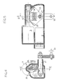
- This pinion output 13 is in engagement with a control pinion 14 specific to slide axially parallel to the axis of the shaft 10 of the motor, but wedged in rotation by a fixed tooth 15 engaged with axial sliding in an external groove 14 '' of the pinion 14, which is connected to the movable core 16 of a fixed electromagnet 17 by a return spring 18.
- the electromagnet 17 When switching from control of the switch to speed selection control, the electromagnet 17 is activated and moves the kernel 16 to the right of the drawing, which, through the pinion of control 14, slides the output gear 13 on the shaft 10 and engages with the reduction pinion 20, the reduction pinion 19 is then released.
- This gear train epicyclic comprises the output pinion 13 'as planetary, and a set of satellites carried by a planet carriers 23 and geared on the one hand with the output pinion 13 ', on the other hand with a crown external tooth 22, which is coupled to a first pinion 21, while the planet carrier 23 is coupled to a second pinion 24.
- the pinion 21 or the pinion 24 can be locked in rotation by a pinion of control 14 'locked in rotation by a fixed tooth 15 (as in Figure 3) and can slide axially thanks to the electromagnet 16, 17 with return spring 18, between two positions: in the position shown on FIG. 4 the control pinion 14 'blocks the first pinion 21 in engagement with the reduction pinion 20 of the selection control, which blocks this pinion 20 in same time as the outer ring gear 22. From this in fact, the planet carrier 23 drives in its rotation the second pinion 24 coupled to the reduction gear 19, this which drives the gearshift.
- control pinion 14 when it is activated, it occupies the position represented in dashed lines for which it blocks the rotation of the second gear 24, which at the same time blocks the rotation of the reduction pinion 19 of the wheelhouse and the satellite carrier 23.
- the outer ring gear 22 is then driven in rotation, as well as the first pinion 21, which drives the wheelhouse selection through of the reduction gear 20.
- Figures 5 and 6 show a first possible embodiment of an elastic system storing the energy of a motor 3 controlled by its power module 2.
- the worm shaft 10 'of this engine is in taken with a toothed sector 25 'of a first plate circular sector shape 25, which can rotate on an end of axis 27 also serving as axis of rotation to another plate in the shape of a circle sector 26 of which he is solidarized.
- a opening, respectively 28 and 29, these openings being facing each other so that they can used to receive a pre-compressed spring 30.
- a one of its ends this spring is held in place by two vertical tabs of plate 25, while its other end it is held in place by two horizontal legs of the plate 26.
- the spring 30 risk of being subjected to failover.
- the power module 2 can control by through the motor 3 the return of the plates 25 and 26 of their respective initial positions.
- FIG. represented a variant in which the parts cooperating elastic system no longer have a relative displacement in rotation but a displacement relative in translation, the general principle of operation being however the same in both case.
- a elastic system including in the same housing 34, mounted at one end on an axis 35, the engine 3, its module of power 2 as well as the elastic system properly said, still referenced in 9.
- This elastic system has a cage 36 slidably mounted on the housing 34 of the electric motor and coupled by the link 37 to a wheelhouse for the selection or passage of speeds, here schematized in 38.
- a core 39 is mounted sliding in this cage 36 and is engaged by a central helical housing 40 on the shaft, for example ball screw 10 '', motor 3.
- Housing in look 41 of the cage 36 and 42 of the core 39 contain a set of precompressed springs 43.
- a limit switch 7 is arranged on the cage 36 to be maneuvered by the arrival at the end of the race of the core 39, and an actuator position sensor schematized at 8 is associated with the shaft 10 '' of the engine.
- crossing and selection trees are rotating, and that it exists in the gearbox at the least a device transforming the movement of rotation of the selection shaft in translation, the structures that can be interchanged.
- the classic gearshift can also be replaced by a multidirectional lever electrical contacts, of the type called "joy stick”.
Landscapes
- Engineering & Computer Science (AREA)
- General Engineering & Computer Science (AREA)
- Mechanical Engineering (AREA)
- Connection Of Motors, Electrical Generators, Mechanical Devices, And The Like (AREA)
- Structure Of Transmissions (AREA)
Description
- un moto réducteur comportant un moteur et au moins un réducteur, propre à fournir l'énergie mécanique nécessaire auxdites commandes, et qui est commandé par un module de puissance ; et
- un système élastique d'emmagasinage de l'énergie mécanique, interposé entre le réducteur et la timonerie, apte à restituer l'énergie emmagasinée à la timonerie.
- un premier motoréducteur, commandé par un premier module de puissance et constitué d'un premier moteur et d'un premier réducteur, propre à fournir l'énergie mécanique nécessaire pour assurer la commande la sélection des vitesses par l'intermédiaire d'une timonerie de sélection,
- un second motoréducteur commandé par un second module de puissance et constitué d'un second moteur et d'un second réducteur, propre à fournir l'énergie mécanique nécessaire pour assurer la commande du passage des vitesses par l'intermédiaire d'une timonerie de passage,
- un système élastique d'emmagasinage de l'énergie mécanique étant interposé entre le réducteur et la timonerie de chacun des premier et second motoréducteurs.
- la figure 1 est schéma synoptique montrant un actionneur électromécanique pour boíte de vitesses mécanique montrant la mise en oeuvre d'un moteur pour la commande de la sélection des vitesses ou de leur passage ;
- la figure 2 est un schéma, conforme à l'invention, synoptique montrant un actionneur électromécanique pour boíte de vitesses mécanique montrant la mise en oeuvre d'un seul moteur pour la commande successive de la sélection des vitesses et de leur passage ;
- la figure 3 montre en coupe axiale schématique un commutateur mécanique utilisable dans le cas de la figure 2 ;
- la figure 4 montre schématiquement un autre commutateur mécanique utilisable dans le cas de la figure 2 ;
- la figure 5 montre en coupe axiale par la ligne V-V de la figure 6 un système élastique d'emmagasinage d'énergie mécanique utilisable dans le cas des figures 1 et 2 ;
- la figure 6 montre ce système en coupe transversale par la ligne VI-VI de la figure 5 ; et
- la figure 7 montre en coupe axiale un autre système élastique d'emmagasinage d'énergie mécanique utilisable dans le cas des figures 1 et 2.
Claims (8)
- Actionneur électromécanique pour une boíte de vitesses mécanique, notamment pour véhicule automobile, destiné à assurer sélectivement, d'une part la commande de la sélection des vitesses par l'intermédiaire d'une timonerie de sélection et, d'autre part, la commande du passage des vitesses par l'intermédiaire d'une timonerie de passage, du type comportant :caractérisé en ce que l'actionneur comporte un seul moteur (3), commandé par un seul module de puissance (2), qui peut être accouplé sélectivement à l'un ou à l'autre de deux réducteurs (4s, 4p) par un commutateur mécanique (9), l'un de ces réducteurs (4s) assurant la commande de la sélection des vitesses et l'autre (4p) la commande du passage des vitesses, par l'intermédiaire des timoneries respectives (1s, 1p).un motoréducteur (3, 4) comportant un moteur (3) et au moins un réducteur, propre à fournir l'énergie mécanique nécessaire auxdites commandes, et qui est commandé par un module de puissance ; etun système élastique (5) d'emmagasinage de l'énergie mécanique, interposé entre le réducteur et la timonerie (1), apte à restituer l'énergie emmagasinée à la timonerie,un interrupteur de fin de course (7) propre à provoquer l'apparition d'un signal représentatif de l'état comprimé (emmagasinage d'énergie) du dit système élastique (5), et ainsi de détecter le fait que la sélection ou l'engagement du rapport souhaité de la boíte a bien été obtenu,
- Actionneur électromécanique selon la revendication 1, caractérisé en ce que ledit commutateur mécanique (9) comporte un électroaimant commandé (16, 17) par le module de puissance (2), le moteur (3) comportant, calé sur son arbre (10), un pignon de sortie coulissant (13), et ledit électroaimant étant associé à un pignon de commande fixe en rotation (14), relié axialement audit pignon de sortie et propre à occuper sélectivement deux positions axialement décalées, à savoir une position pour laquelle il amène ledit pignon de sortie (13) du moteur (3) en prise avec un premier pignon réducteur (20) accouplé à la timonerie de sélection de la boíte, et une position pour laquelle il amène ledit pignon de sortie (13) du moteur (3) en prise avec un second pignon réducteur (19) accouplé à la timonerie de passage, le premier pignon réducteur (20) étant alors bloqué en rotation.
- Actionneur électromécanique selon la revendication 1, caractérisé en ce que ledit commutateur mécanique (9) comporte un électroaimant commandé (16, 17) par le module de puissance (2), le moteur (3) comportant, calé sur son arbre (10), un pignon de sortie (13') constituant le planétaire d'un train d'engrenages réducteur épicycloïdal, et ledit électroaimant (16, 17) étant associé à un pignon de commande (14') fixe en rotation et propre à occuper sélectivement deux positions axialement décalées, à savoir une position pour laquelle il bloque en rotation un premier pignon (21) accouplé à la couronne dentée extérieure (22) du train, auquel cas le porte-satellites (23) peut entraíner la timonerie de commande de passage des vitesses (1p) avec un premier rapport de réduction, et une position pour laquelle il bloque en rotation un second pignon (24) accouplé audit porte-satellites (23), auquel cas ladite couronne dentée extérieure (22) peut entraíner la timonerie de sélection des vitesses (1s) avec un second rapport de réduction, la timonerie non entraínée étant ainsi à chaque fois bloquée.
- Actionneur électromécanique selon l'une quelconque des revendications précédentes, caractérisé en ce que ledit système élastique (5) comporte au moins deux plaques pivotantes (25, 26) reliées l'une à l'autre par un ressort (30), la première (25) étant accouplée à l'arbre de sortie (10') d'un moteur électrique (3), la seconde (26) à un arbre mené (27) accouplé à une timonerie (33) de commande de sélection ou de passage, ladite autre plaque (26) pouvant ainsi occuper deux positions angulairement décalées, à savoir une position bloquée par ladite timonerie (33), pour laquelle ledit ressort (30) emmagasine de l'énergie du fait de la rotation dudit arbre de sortie (10'), et une position active au passage de laquelle la détente dudit ressort (30) provoque la manoeuvre de ladite timonerie (33), l'arrivée dans cette position active provoquant l'actionnement dudit interrupteur (7) de fin de course.
- Actionneur électromécanique selon la revendication 4, caractérisé en ce que ledit moteur électrique (3) est constitué par un motoréducteur à arbre à vis sans fin (10') en prise avec un secteur denté (25') de ladite première plaque (25).
- Actionneur électromécanique selon l'une quelconque des revendications 1 à 3, caractérisé en ce que ledit système élastique (5) comporte d'une part une cage (36) montée coulissante sur un carter (34) de moteur électrique (3) et accouplée à une timonerie (38) de commande de sélection ou de passage, et d'autre part un noyau (39) monté coulissant par rapport à ladite cage, accouplé à l'arbre de sortie (10'') dudit moteur (3) et relié à la cage (36) par un ou des ressorts (43), ladite cage (36) pouvant ainsi occuper deux positions axialement décalées, à savoir une position bloquée par ladite timonerie (38), pour laquelle le ou lesdits ressorts (43) emmagasinent de l'énergie du fait de la rotation dudit arbre (10'') de sortie, et une position active au passage de laquelle la détente du ou desdits ressorts (43) provoque la manoeuvre de ladite timonerie (38), l'arrivée dans cette position active provoquant l'actionnement dudit interrupteur (7) de fin de course.
- Actionneur électromécanique selon la revendication 6, caractérisé en ce que ledit moteur électrique (3) est constitué par un motoréducteur à vis à billes (10'') ou à gilets trapézoïdaux en prise avec un logement hélicoïdal (40) dudit noyau (39).
- Actionneur électromécanique selon l'une quelconque des revendications 4 à 6, caractérisé en ce qu'un capteur de position angulaire (8) de l'unité motrice est associé audit arbre de sortie (10', 10'') du moteur électrique (3) ou à un organe mené après réduction.
Applications Claiming Priority (3)
| Application Number | Priority Date | Filing Date | Title |
|---|---|---|---|
| FR9805309 | 1998-04-28 | ||
| FR9805309A FR2777834B1 (fr) | 1998-04-28 | 1998-04-28 | Actionneur electromecanique pour boite de vitesse |
| PCT/FR1999/001008 WO1999056040A1 (fr) | 1998-04-28 | 1999-04-28 | Actionneur electromecanique pour boite de vitesses mecanique |
Publications (2)
| Publication Number | Publication Date |
|---|---|
| EP0990098A1 EP0990098A1 (fr) | 2000-04-05 |
| EP0990098B1 true EP0990098B1 (fr) | 2003-09-03 |
Family
ID=9525750
Family Applications (1)
| Application Number | Title | Priority Date | Filing Date |
|---|---|---|---|
| EP99915859A Expired - Lifetime EP0990098B1 (fr) | 1998-04-28 | 1999-04-28 | Actionneur electromecanique pour boite de vitesses mecanique |
Country Status (4)
| Country | Link |
|---|---|
| EP (1) | EP0990098B1 (fr) |
| DE (1) | DE19980838B4 (fr) |
| FR (1) | FR2777834B1 (fr) |
| WO (1) | WO1999056040A1 (fr) |
Families Citing this family (14)
| Publication number | Priority date | Publication date | Assignee | Title |
|---|---|---|---|---|
| FR2795831B1 (fr) | 1999-06-30 | 2001-10-12 | Valeo | Actionneur electromecanique a effort controle et application notamment a la commande d'une boite de vitesses par exemple de vehicule automobile |
| FR2813935B1 (fr) | 2000-09-08 | 2002-11-29 | Renault | Boite de vitesses a actionneur de passage |
| FR2820484B1 (fr) | 2001-02-02 | 2003-04-04 | Renault | Boite de vitesses mecanique a actionneurs de passage et dispositif de couplage correspondant |
| FR2823823B1 (fr) * | 2001-04-24 | 2003-05-23 | Valeo | Procede d'actionnement et actionneur pour la commande du passage des vitesses d'une boite de vitesses de vehicule automobile |
| FR2833331B1 (fr) | 2001-12-07 | 2004-05-14 | Renault | Boite de vitesses automatisee a passages sous couple |
| FR2835030B1 (fr) * | 2002-01-22 | 2005-05-06 | Valeo | Procede et dispositif de commande du passage des vitesses dans une boite de vitesses de vehicule automobile |
| EP1427213A1 (fr) | 2002-12-06 | 2004-06-09 | Thomson Licensing S.A. | Procédé d'enregistrement de données, procédé pour la localisation d'ensembles de données, structure de données et support d'enregistrement |
| FR2861153B1 (fr) * | 2004-11-17 | 2006-04-28 | Valeo Embrayages | Ensemble de commande pour boite de vitesses robotisee. |
| FR2861154B1 (fr) * | 2004-11-17 | 2007-09-28 | Valeo Embrayages | Ensemble de commande pour boite de vitesses robotisee. |
| FR2861152B1 (fr) * | 2004-11-17 | 2008-10-10 | Valeo Embrayages | Ensemble de commande pour boite de vitesses robotisee. |
| FR2913475B1 (fr) * | 2007-03-07 | 2009-08-28 | Renault Sas | Actionneur electromecanique pour boite de vitesses de vehicule automobile et dispositif d'embrayage pourvu d'un tel actionneur. |
| FR2988153B1 (fr) * | 2012-03-14 | 2014-04-18 | Peugeot Citroen Automobiles Sa | Commande de crabot d'une boite de vitesses, comportant un basculeur |
| DE102018131892A1 (de) * | 2017-12-13 | 2019-06-13 | Schaeffler Technologies AG & Co. KG | Parksperre - Stellmutter |
| FR3087242B1 (fr) * | 2018-10-15 | 2021-07-02 | Renault Sas | Agencement pour la commande interne de selection d'une boite de vitesses |
Family Cites Families (6)
| Publication number | Priority date | Publication date | Assignee | Title |
|---|---|---|---|---|
| US4449416A (en) * | 1981-09-04 | 1984-05-22 | J. I. Case Company | Transmission control system |
| US4498350A (en) * | 1982-09-20 | 1985-02-12 | Eaton Corporation | Shifting mechanism |
| US4619151A (en) * | 1985-04-19 | 1986-10-28 | Rockwell International Corporation | Two speed axle shift actuator |
| DE3611093A1 (de) * | 1986-04-03 | 1987-10-08 | Opel Adam Ag | Kraftfahrzeug mit allradantrieb |
| GB2207715B (en) * | 1987-07-28 | 1991-10-09 | Gaydon Techn Ltd | Vehicle transmissions |
| FR2693808B1 (fr) * | 1992-07-17 | 1994-09-16 | Renault | Dispositif d'assistance mécanique au passage des vitesses. |
-
1998
- 1998-04-28 FR FR9805309A patent/FR2777834B1/fr not_active Expired - Lifetime
-
1999
- 1999-04-28 DE DE19980838T patent/DE19980838B4/de not_active Expired - Lifetime
- 1999-04-28 WO PCT/FR1999/001008 patent/WO1999056040A1/fr not_active Ceased
- 1999-04-28 EP EP99915859A patent/EP0990098B1/fr not_active Expired - Lifetime
Also Published As
| Publication number | Publication date |
|---|---|
| WO1999056040A1 (fr) | 1999-11-04 |
| EP0990098A1 (fr) | 2000-04-05 |
| FR2777834B1 (fr) | 2000-06-23 |
| FR2777834A1 (fr) | 1999-10-29 |
| DE19980838B4 (de) | 2010-04-08 |
| DE19980838T1 (de) | 2000-08-10 |
Similar Documents
| Publication | Publication Date | Title |
|---|---|---|
| FR2558781A1 (fr) | Siege de vehicule manoeuvrable par moteur electrique | |
| WO2001065152A1 (fr) | Dispositif de transmission automatise a engrenages, en particulier pour vehicule automobile | |
| WO1999056040A1 (fr) | Actionneur electromecanique pour boite de vitesses mecanique | |
| EP0449739B1 (fr) | Dispositif de commande motorisé de changement de rapport de transmission pour boîte de vitesses, en particulier pour véhicules automobiles | |
| EP1108169B1 (fr) | Actionneur electromecanique pour boite de vitesse de vehicule automobile | |
| EP0490730A1 (fr) | Dispositif de commande motorisé de changement de rapports de transmission pour boîte de vitesses, en particulier pour véhicules automobiles | |
| FR2789743A1 (fr) | Boite de vitesses automatique | |
| FR2774447A1 (fr) | Vehicule equipe d'un dispositif de manoeuvre automatisee d'une boite a vitesses | |
| FR2814524A1 (fr) | Actionneur pour boite de vitesses mecanique de vehicules | |
| FR2492558A1 (fr) | Mecanisme d'assistance rotative, notamment pour direction de vehicule | |
| FR2833331A1 (fr) | Boite de vitesses automatisee a passages sous couple | |
| FR2938692A1 (fr) | Commande d'appareillage electrique haute ou moyenne tension a mecanisme a double accrochage ameliore et procede d'armement associe. | |
| FR2714952A1 (fr) | Dispositif mécanique de sélection linéaire pour boîte de vitesses conventionnelle et sélection en H. | |
| FR2805020A1 (fr) | Boite de vitesses a freinage selectif d'arbre moteur et procede de mise en oeuvre | |
| WO1996023995A1 (fr) | Dispositif de commande d'une boite de vitesse | |
| FR2844570A1 (fr) | Dispositif de selection et de passage de vitesses pour une boite de vitesse pilotee de vehicule automobile | |
| EP0859922A1 (fr) | Dispositif de securite pour boite de vitesses mecanique | |
| FR2822517A1 (fr) | Dispositif de commande de changement de rapport de transmission dans une boite de vitesses | |
| EP0169769B1 (fr) | Dispositif de commande à câble pour crabotage, notamment pour groupes de transmission de véhicules automobiles et groupe de transmission de véhicule automobile comportant un tel dispositif de commande | |
| FR2631900A1 (fr) | Vehicule de travaux a quatre roues motrices | |
| EP1186809A1 (fr) | Boíte de vitesses à actionneur de passage | |
| EP0630495B1 (fr) | Dispositif d'actionnement d'un systeme tel qu'un embrayage ou une boite de vitesse | |
| EP2105637B1 (fr) | Actionneur électromécanique pour boîte de vitesses automatique comprenant des moyens de progressivité | |
| EP1229274B1 (fr) | Boíte de vitesses mécanique à actionneurs de passage | |
| EP2050988B1 (fr) | Dispositif de freinage d'un arbre moteur d'une boîte de vitesses, pour l'engagement d'un pignon de marche arrière |
Legal Events
| Date | Code | Title | Description |
|---|---|---|---|
| PUAI | Public reference made under article 153(3) epc to a published international application that has entered the european phase |
Free format text: ORIGINAL CODE: 0009012 |
|
| 17P | Request for examination filed |
Effective date: 20000120 |
|
| AK | Designated contracting states |
Kind code of ref document: A1 Designated state(s): GB IT |
|
| RIN1 | Information on inventor provided before grant (corrected) |
Inventor name: VUILLEMIN, JEAN-CLAUDE Inventor name: LEBAS, GILLES Inventor name: BEZIAN, ALAIN Inventor name: RANDRIAZANAMPARANY, ROLAND-VEVE Inventor name: MAUREL, HERVE Inventor name: VALERO, THOMAS Inventor name: VERSHAEVE, JEAN-MANUEL |
|
| 17Q | First examination report despatched |
Effective date: 20020205 |
|
| GRAH | Despatch of communication of intention to grant a patent |
Free format text: ORIGINAL CODE: EPIDOS IGRA |
|
| RAP1 | Party data changed (applicant data changed or rights of an application transferred) |
Owner name: VALEO EMBRAYAGES S.A.S. |
|
| GRAS | Grant fee paid |
Free format text: ORIGINAL CODE: EPIDOSNIGR3 |
|
| GRAA | (expected) grant |
Free format text: ORIGINAL CODE: 0009210 |
|
| AK | Designated contracting states |
Kind code of ref document: B1 Designated state(s): GB IT |
|
| REG | Reference to a national code |
Ref country code: GB Ref legal event code: FG4D Free format text: NOT ENGLISH |
|
| GBT | Gb: translation of ep patent filed (gb section 77(6)(a)/1977) |
Effective date: 20031104 |
|
| PLBE | No opposition filed within time limit |
Free format text: ORIGINAL CODE: 0009261 |
|
| STAA | Information on the status of an ep patent application or granted ep patent |
Free format text: STATUS: NO OPPOSITION FILED WITHIN TIME LIMIT |
|
| 26N | No opposition filed |
Effective date: 20040604 |
|
| PGFP | Annual fee paid to national office [announced via postgrant information from national office to epo] |
Ref country code: IT Payment date: 20180417 Year of fee payment: 20 |
|
| PGFP | Annual fee paid to national office [announced via postgrant information from national office to epo] |
Ref country code: GB Payment date: 20180417 Year of fee payment: 20 |
|
| REG | Reference to a national code |
Ref country code: GB Ref legal event code: PE20 Expiry date: 20190427 |
|
| PG25 | Lapsed in a contracting state [announced via postgrant information from national office to epo] |
Ref country code: GB Free format text: LAPSE BECAUSE OF EXPIRATION OF PROTECTION Effective date: 20190427 |