EP0989795A2 - Refrigeration system for electronic components - Google Patents
Refrigeration system for electronic components Download PDFInfo
- Publication number
- EP0989795A2 EP0989795A2 EP99307561A EP99307561A EP0989795A2 EP 0989795 A2 EP0989795 A2 EP 0989795A2 EP 99307561 A EP99307561 A EP 99307561A EP 99307561 A EP99307561 A EP 99307561A EP 0989795 A2 EP0989795 A2 EP 0989795A2
- Authority
- EP
- European Patent Office
- Prior art keywords
- compressor
- combination
- manifold
- evaporator
- sorbate
- Prior art date
- Legal status (The legal status is an assumption and is not a legal conclusion. Google has not performed a legal analysis and makes no representation as to the accuracy of the status listed.)
- Withdrawn
Links
Images


Classifications
-
- H—ELECTRICITY
- H05—ELECTRIC TECHNIQUES NOT OTHERWISE PROVIDED FOR
- H05K—PRINTED CIRCUITS; CASINGS OR CONSTRUCTIONAL DETAILS OF ELECTRIC APPARATUS; MANUFACTURE OF ASSEMBLAGES OF ELECTRICAL COMPONENTS
- H05K7/00—Constructional details common to different types of electric apparatus
- H05K7/20—Modifications to facilitate cooling, ventilating, or heating
- H05K7/2029—Modifications to facilitate cooling, ventilating, or heating using a liquid coolant with phase change in electronic enclosures
- H05K7/20354—Refrigerating circuit comprising a compressor
-
- F—MECHANICAL ENGINEERING; LIGHTING; HEATING; WEAPONS; BLASTING
- F25—REFRIGERATION OR COOLING; COMBINED HEATING AND REFRIGERATION SYSTEMS; HEAT PUMP SYSTEMS; MANUFACTURE OR STORAGE OF ICE; LIQUEFACTION SOLIDIFICATION OF GASES
- F25B—REFRIGERATION MACHINES, PLANTS OR SYSTEMS; COMBINED HEATING AND REFRIGERATION SYSTEMS; HEAT PUMP SYSTEMS
- F25B17/00—Sorption machines, plants or systems, operating intermittently, e.g. absorption or adsorption type
- F25B17/08—Sorption machines, plants or systems, operating intermittently, e.g. absorption or adsorption type the absorbent or adsorbent being a solid, e.g. salt
-
- F—MECHANICAL ENGINEERING; LIGHTING; HEATING; WEAPONS; BLASTING
- F25—REFRIGERATION OR COOLING; COMBINED HEATING AND REFRIGERATION SYSTEMS; HEAT PUMP SYSTEMS; MANUFACTURE OR STORAGE OF ICE; LIQUEFACTION SOLIDIFICATION OF GASES
- F25B—REFRIGERATION MACHINES, PLANTS OR SYSTEMS; COMBINED HEATING AND REFRIGERATION SYSTEMS; HEAT PUMP SYSTEMS
- F25B35/00—Boiler-absorbers, i.e. boilers usable for absorption or adsorption
- F25B35/04—Boiler-absorbers, i.e. boilers usable for absorption or adsorption using a solid as sorbent
-
- F—MECHANICAL ENGINEERING; LIGHTING; HEATING; WEAPONS; BLASTING
- F25—REFRIGERATION OR COOLING; COMBINED HEATING AND REFRIGERATION SYSTEMS; HEAT PUMP SYSTEMS; MANUFACTURE OR STORAGE OF ICE; LIQUEFACTION SOLIDIFICATION OF GASES
- F25B—REFRIGERATION MACHINES, PLANTS OR SYSTEMS; COMBINED HEATING AND REFRIGERATION SYSTEMS; HEAT PUMP SYSTEMS
- F25B39/00—Evaporators; Condensers
- F25B39/02—Evaporators
- F25B39/026—Evaporators specially adapted for sorption type systems
-
- F—MECHANICAL ENGINEERING; LIGHTING; HEATING; WEAPONS; BLASTING
- F25—REFRIGERATION OR COOLING; COMBINED HEATING AND REFRIGERATION SYSTEMS; HEAT PUMP SYSTEMS; MANUFACTURE OR STORAGE OF ICE; LIQUEFACTION SOLIDIFICATION OF GASES
- F25B—REFRIGERATION MACHINES, PLANTS OR SYSTEMS; COMBINED HEATING AND REFRIGERATION SYSTEMS; HEAT PUMP SYSTEMS
- F25B49/00—Arrangement or mounting of control or safety devices
- F25B49/04—Arrangement or mounting of control or safety devices for sorption type machines, plants or systems
- F25B49/046—Operating intermittently
-
- F—MECHANICAL ENGINEERING; LIGHTING; HEATING; WEAPONS; BLASTING
- F25—REFRIGERATION OR COOLING; COMBINED HEATING AND REFRIGERATION SYSTEMS; HEAT PUMP SYSTEMS; MANUFACTURE OR STORAGE OF ICE; LIQUEFACTION SOLIDIFICATION OF GASES
- F25D—REFRIGERATORS; COLD ROOMS; ICE-BOXES; COOLING OR FREEZING APPARATUS NOT OTHERWISE PROVIDED FOR
- F25D23/00—General constructional features
- F25D23/12—Arrangements of compartments additional to cooling compartments; Combinations of refrigerators with other equipment, e.g. stove
-
- H—ELECTRICITY
- H01—ELECTRIC ELEMENTS
- H01L—SEMICONDUCTOR DEVICES NOT COVERED BY CLASS H10
- H01L23/00—Details of semiconductor or other solid state devices
- H01L23/34—Arrangements for cooling, heating, ventilating or temperature compensation ; Temperature sensing arrangements
- H01L23/42—Fillings or auxiliary members in containers or encapsulations selected or arranged to facilitate heating or cooling
- H01L23/427—Cooling by change of state, e.g. use of heat pipes
-
- H—ELECTRICITY
- H05—ELECTRIC TECHNIQUES NOT OTHERWISE PROVIDED FOR
- H05B—ELECTRIC HEATING; ELECTRIC LIGHT SOURCES NOT OTHERWISE PROVIDED FOR; CIRCUIT ARRANGEMENTS FOR ELECTRIC LIGHT SOURCES, IN GENERAL
- H05B6/00—Heating by electric, magnetic or electromagnetic fields
- H05B6/64—Heating using microwaves
- H05B6/70—Feed lines
- H05B6/701—Feed lines using microwave applicators
-
- H—ELECTRICITY
- H05—ELECTRIC TECHNIQUES NOT OTHERWISE PROVIDED FOR
- H05B—ELECTRIC HEATING; ELECTRIC LIGHT SOURCES NOT OTHERWISE PROVIDED FOR; CIRCUIT ARRANGEMENTS FOR ELECTRIC LIGHT SOURCES, IN GENERAL
- H05B6/00—Heating by electric, magnetic or electromagnetic fields
- H05B6/64—Heating using microwaves
- H05B6/80—Apparatus for specific applications
- H05B6/802—Apparatus for specific applications for heating fluids
-
- H—ELECTRICITY
- H05—ELECTRIC TECHNIQUES NOT OTHERWISE PROVIDED FOR
- H05B—ELECTRIC HEATING; ELECTRIC LIGHT SOURCES NOT OTHERWISE PROVIDED FOR; CIRCUIT ARRANGEMENTS FOR ELECTRIC LIGHT SOURCES, IN GENERAL
- H05B6/00—Heating by electric, magnetic or electromagnetic fields
- H05B6/64—Heating using microwaves
- H05B6/80—Apparatus for specific applications
- H05B6/808—Microwave heating adapted for vending machines
-
- H—ELECTRICITY
- H05—ELECTRIC TECHNIQUES NOT OTHERWISE PROVIDED FOR
- H05K—PRINTED CIRCUITS; CASINGS OR CONSTRUCTIONAL DETAILS OF ELECTRIC APPARATUS; MANUFACTURE OF ASSEMBLAGES OF ELECTRICAL COMPONENTS
- H05K7/00—Constructional details common to different types of electric apparatus
- H05K7/20—Modifications to facilitate cooling, ventilating, or heating
- H05K7/2029—Modifications to facilitate cooling, ventilating, or heating using a liquid coolant with phase change in electronic enclosures
- H05K7/20309—Evaporators
-
- H—ELECTRICITY
- H05—ELECTRIC TECHNIQUES NOT OTHERWISE PROVIDED FOR
- H05K—PRINTED CIRCUITS; CASINGS OR CONSTRUCTIONAL DETAILS OF ELECTRIC APPARATUS; MANUFACTURE OF ASSEMBLAGES OF ELECTRICAL COMPONENTS
- H05K7/00—Constructional details common to different types of electric apparatus
- H05K7/20—Modifications to facilitate cooling, ventilating, or heating
- H05K7/2029—Modifications to facilitate cooling, ventilating, or heating using a liquid coolant with phase change in electronic enclosures
- H05K7/20363—Refrigerating circuit comprising a sorber
-
- H—ELECTRICITY
- H05—ELECTRIC TECHNIQUES NOT OTHERWISE PROVIDED FOR
- H05K—PRINTED CIRCUITS; CASINGS OR CONSTRUCTIONAL DETAILS OF ELECTRIC APPARATUS; MANUFACTURE OF ASSEMBLAGES OF ELECTRICAL COMPONENTS
- H05K7/00—Constructional details common to different types of electric apparatus
- H05K7/20—Modifications to facilitate cooling, ventilating, or heating
- H05K7/20536—Modifications to facilitate cooling, ventilating, or heating for racks or cabinets of standardised dimensions, e.g. electronic racks for aircraft or telecommunication equipment
-
- F—MECHANICAL ENGINEERING; LIGHTING; HEATING; WEAPONS; BLASTING
- F25—REFRIGERATION OR COOLING; COMBINED HEATING AND REFRIGERATION SYSTEMS; HEAT PUMP SYSTEMS; MANUFACTURE OR STORAGE OF ICE; LIQUEFACTION SOLIDIFICATION OF GASES
- F25B—REFRIGERATION MACHINES, PLANTS OR SYSTEMS; COMBINED HEATING AND REFRIGERATION SYSTEMS; HEAT PUMP SYSTEMS
- F25B2333/00—Details of boilers; Analysers; Rectifiers
- F25B2333/005—Details of boilers; Analysers; Rectifiers the generator or boiler uses electromagnetic energy in the form of microwaves for desorbing the sorbate from the sorbate/sorbent compound
-
- H—ELECTRICITY
- H01—ELECTRIC ELEMENTS
- H01L—SEMICONDUCTOR DEVICES NOT COVERED BY CLASS H10
- H01L2924/00—Indexing scheme for arrangements or methods for connecting or disconnecting semiconductor or solid-state bodies as covered by H01L24/00
- H01L2924/0001—Technical content checked by a classifier
- H01L2924/0002—Not covered by any one of groups H01L24/00, H01L24/00 and H01L2224/00
-
- H—ELECTRICITY
- H01—ELECTRIC ELEMENTS
- H01L—SEMICONDUCTOR DEVICES NOT COVERED BY CLASS H10
- H01L2924/00—Indexing scheme for arrangements or methods for connecting or disconnecting semiconductor or solid-state bodies as covered by H01L24/00
- H01L2924/30—Technical effects
- H01L2924/301—Electrical effects
- H01L2924/3011—Impedance
Definitions
- the present invention relates to sorption systems wherein a sorbate is alternately adsorbed onto and desorbed from a sorbent. More particularly, the invention relates to a refrigeration sorption system for cooling electrical components wherein the sorbate is desorbed from the sorbent using electromagnetic waves.
- Certain electrical components such as the microprocessors in conventional computers, generate a substantial amount of heat during operation. It has been determined that the performance of a microprocessor can be enhanced significantly by effectively removing this heat. In addition, in accordance with conventional semiconductor practice, it is known that the operating speed of a microprocessor can be greatly increased if the microprocessor is operated at low temperatures.
- adsorption and desorption systems which will be referred to herein as "sorption systems"
- a first substance called a sorbate is alternately adsorbed onto and then desorbed from a second substance called a sorbent.
- Specific sorbates and sorbents will usually be selected for a particular sorption system to produce a desired effect, which is dependent on the affinity of the two substances.
- an adsorption reaction which is also referred to as the adsorb cycle or the adsorb portion of the sorption cycle, the sorbate is drawn onto and combines with the sorbate to produce a sorbate/sorbent compound.
- the desorption reaction which is also called the desorb cycle or the desorb portion of the sorption cycle
- energy is supplied to the sorbate/sorbent compound to break the bonds between the sorbate and sorbent molecules and thereby desorb, or in other words separate or drive off, the sorbate from the sorbent.
- Substantial energy is imparted to the sorbate during the desorption reaction, and this energy can be harnessed for various uses.
- An exemplary refrigeration sorption system may use a polar refrigerant, such as ammonia, as the sorbate and a metal halide salt, such as strontium bromide, as the sorbent.
- a polar refrigerant such as ammonia
- a metal halide salt such as strontium bromide
- the refrigerant molecules are driven off of the salt and, into a relatively high pressure, high energy gaseous state.
- the refrigerant gas is subsequently condensed and then evaporated to produce a cooling effect.
- the evaporated refrigerant gas is then channeled back to the sorber, where it is once again adsorbed onto the salt in an adsorption reaction.
- the sorption cycle is repeated numerous times depending on the cooling requirements of the refrigeration system.
- the desorption energy is supplied by a conventional heater.
- a great deal of thermal energy is required to stochastically heat the sorbate/sorbent compound to the degree sufficient to break the bonds between the sorbate and sorbent molecules.
- the sorbate, sorbent and sorber are significantly heated, and substantial time and/or energy are required to remove this sensible heat and cool the sorbers and sorbent before the next adsorption reaction can proceed.
- the desorption energy is supplied in the form of electromagnetic waves, such as radio frequency waves or microwaves, generated by, for example, a magnetron.
- electromagnetic waves instead of heating the sorbate/sorbent compound, the electromagnetic waves selectively pump electrical energy into each sorbate-sorbent bond until the bond is broken and the sorbate molecule is separated from the sorbent molecule. Therefore, the sorbate, sorbent and sorber are not heated during the desorption reaction and consequently do not need to be cooled before the next adsorption reaction can proceed.
- the desorption reaction is essentially isothermal, the overall performance of the refrigeration system is greatly improved.
- a refrigeration system for cooling an electrical component which comprises a sorber having a housing defining an enclosure, a sorbate/sorbent compound located within the enclosure, the sorber including a port through which a sorbate may be communicated into and out of the enclosure, and means for electrically coupling the sorber to an electromagnetic wave generator, wherein electromagnetic waves transmitted by the electromagnetic wave generator are propagated through the enclosure to desorb the sorbate from the sorbate/sorbent compound.
- the refrigeration system may also include a condenser connected to the port downstream of the sorber, an evaporator connected between the condenser and the port and positioned in close proximity to the electrical component, and a controllable expansion valve interposed between the condenser and the evaporator.
- a condenser connected to the port downstream of the sorber
- an evaporator connected between the condenser and the port and positioned in close proximity to the electrical component
- a controllable expansion valve interposed between the condenser and the evaporator.
- the absorbent bed be able to provide sufficient heat and mass transport capabilities to allow for rapid adsorption of the refrigerant vapor. Without sufficient heat removal, the mass flow would have to be reduced, or alternately cooling power would be lost as the adsorption pressure would rise with sorbent bed temperature. Consequently, the goal is to maintain the adsorbent bed as close to the hot side heat rejection temperature as possible.
- the electromagnetic nature of the desorption phenomena places further restrictions on the architecture of the reactors as it cannot interfere with the propagation of microwave plane waves (TEM).
- microchannel reactor design is provided to satisfy the foregoing requirements. Although microchannels are often envisioned as being rectangular parallel channels, the exact geometry of the channels has very little effect on heat and mass transfer characteristics. Rather, the performance of the channels is largely dictated by channel depth and flow rate parameters. Flexibility and channel geometry accommodate the electromagnetic compatibility requirements of the reactor.
- Microchannel reactors operate on the principle that within a microchannel, the thermal boundary layer is structurally constrained to less than half of the width of the fluid channel. Heat transfer and laminar and transition flow regimes vary significantly from macroscale channels. Heat transfer in flow regimes is coupled to liquid temperature, velocity and channel size.
- One achievable advantage is that the refrigerator and component cooled thereby can be made so as to be conveniently removable from the system for upgrade or maintenance.
- the desorption compressor can be made physically compact. This permits the compressor to be placed inside the removable module which includes the electronic components.
- the removable interface is associated with the hot end condenser of the refrigeration system.
- the hot side condenser is either a part of a countercurrent liquid-to-liquid heat exchanger or is cooled by evaporating a liquid from the hot surface.
- the demountable interface is the low pressure liquid loop to the heat exchanger. Detaching the module from the low pressure liquid loop is preferably accomplished using conventional double ended shut off fluid disconnects.
- isolation of the system from the atmosphere is obtained by enclosing the unit in a vacuum can.
- the hot end condenser may be used as one surface of the vacuum can (or a portion thereof) or be in close heat transferring proximity thereto.
- the compressor, evaporator, and cooled electronic components are supported away from the surface of the vacuum can so that there is no direct connection between an external surface of the vacuum can and the evaporator. This arrangement makes water vapor condensation unlikely and prevents corrosion of parts.
- the high speed electrical signal connections to the electronic components may be made by means of optical coupling, utilizing fiber optics, or by free space transmission through a window, in all situations providing for best thermal performance. It is also possible to provide such connections using a thin film on a polymer or glass flex circuit, although such a connection has potential difficulties in balancing the conflicting requirements of high thermal impedance with low electrical losses.
- DC Power for the electronic components may be brought into the vacuum can through power feed-throughs which are thermally lagged to the heat end condenser before connecting to the cooled components.
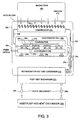
- Fig. 1 illustrates schematically the interrelationship of the components of an embodiment of the present invention.
- the particular electronic components 21 mounted on board 22 are subject to wide variation. In general they are chips or the like which emit heat and which operate at optimum efficiency at reduced temperatures.
- the evaporator 26 In close relationship to the components 21 is the evaporator 26 which emits cold gaseous fluid through emission apertures in porous ceramic blocks 27 inset into the metal evaporator 26. Porous metal or glass frit plugs are likewise suitable.
- the number and the location of blocks 27 is subject of wide variation but, as shown in Fig. 1, are located immediately opposite a corresponding component 21. Channels 28 within the evaporator 26 interconnect blocks 27.
- the blocks 27 may function as valves to control emission of gas or a separate expansion valve 25 may also be used.
- Board 22 and evaporator 26 are isolated within a cell 23 which collects the gas emitted through apertures 27.
- Preferably standoffs 24 which may be of any of a variety of
- Cell 23 is connected by conduit 34 to compressor 33 and thence by conduit 32 to condenser 31.
- the compressed, condensed gases are then recirculated by means of conduit 23 to evaporator 26 preferably through expansion valve 25.
- Compressor 33 is hereinafter discussed in detail.
- condenser 31 comprises at least a portion of one wall of vacuum can 36 or is in close proximity thereto so that heat transfer through the vacuum can occurs.
- a host heat exchanger 37 which absorbs heat from condenser 31.
- the liquid-to-liquid exchange of heat between condenser 36 and heat exchanger may be of any suitable type.
- Located apart from vacuum can 36 and heat exchanger 37 (it being understood that the latter is physically attached to condenser 31 and to can 36) is a host pump and heat exchanger 38.
- Heat exchanger 38 may be of widely different types, well understood in this art, preferably of a liquid-to-air type.
- One such device is LYTRON 5000 Series.
- the connections between exchanger 37 and exchanger 38 are such that decoupling may be readily accomplished as by means of quick disconnect elements 39. Snap-Tite Series 28-1 or other quick disconnects are suitable.
- An optical I/O 41 which passes through the can 36 and cell 23 may control the electronic components 21 or other means as heretofore discussed may be substituted, such as electrical I/OS.
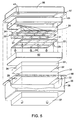
- the vacuum can 36 may be fabricated in two parts namely an upper half 56 having a peripheral external flange 57 and a lower half 58 having a flange 59 which mates with flange 57.
- cell 23 may comprise an upper half 61 and a lower half 62 which are suitably sealed together.
- Fig. 2 illustrates a modification of Fig. 1 wherein compressor 33a is located adjacent a wall of vacuum can 36a, the wall being pervious through a window and wave guide 47 to emissions from magnetron 46.
- compressor 33a is provided with probes 48 which serve as antennas for e field emissions from the magnetron 46.
- Fig. 3 is a further modification resembling Fig. 2 wherein the loop antennae 51 are of a different style than the elements 48 of Fig. 2.
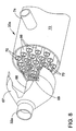
- FIG. 7 A series of representative compressors are illustrated and described herein. It will be understood that these are merely representative of compressors which may be used in embodiments of the invention.
- FIGs. 7 and 8 a plurality of parallel tubes 66 each lined with a sorbate as hereinabove defined is provided.
- the compressor shown in Figs. 7-8 is round in cross-section, other shapes may be used.
- a manifold 67 At one end thereof is a manifold 67 into which the output of condenser 31 is conveyed so that the gas flows through the tubes 66 and interacts with the sorbate thereon.
- RF connector 68 entering the compressor 33a through manifold 67 is RF connector 68 which leads to a splitter 69 having a plurality of applicators 70 leading down through the tubes 66.
- microwave or other waves are applied in the insides of the tubes 67 causing the gas to be released into manifold 71 at the opposite end of the compressor 33a, from which the gases may be conducted to evaporator 26 by means of conduit 34a.
- the tubes 66 may be enclosed in a jacket 72.
- a coolant liquid may be introduced into the jacket 72 through inlet port 73 and conducted out through outlet port 74.
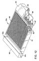
- Figs. 9-11 also shows a coaxial seal applicator array, but differs in the excitation mechanism and size of the applicators.
- the compressor 33b is rectangular in shape. It will be understood that the shape is subject to variation.
- compressor 33b is formed with a body 81 into which are recessed pockets 82 each lined with a sorbent.
- Applicators 83 are introduced through seals 84 in the top of body 81 and extend down through the pockets 82. Applicators 83 may resemble the probe antennas 48 shown in Fig. 2 or may be otherwise constructed.
- Bottom plate 86 is sealed to body 81 and is formed with passageways 87 connected to conduits 32 and 34 (not shown).
- Ducts 88 interconnect pockets 82 with passageways 87 as best shown in Fig. 10.
- cooling passageways 89 may be formed in body 81 for cooling purposes.
- FIGs. 12-14 illustrate another compressor 33c having a flat coaxial applicator array.
- Block 91 is formed with parallel longitudinal bores 92, each lined with sorbent.
- manifold 93 having an RF connector 94 leading to a splitter 96 within the manifold 93.
- splitter 96 lead waveguide applicators 97, one of which extends down through the longitudinal axis of each bore 92.
- manifold 98 At the end of block 91 opposite manifold 93 is a manifold 98 having connector 32c at one end and connector 34c at the opposite end.
- optional longitudinal grooves 99 may be formed on the exterior of block 91 and a cover (not shown) over block 91 provides for circulation of cooling fluid through the grooves 99.
- FIG. 15-18 Still another compressor 33d is shown in Figs. 15-18.
- the applicator may be fabricated using lithographic techniques.
- block 101 is provided with a cover 102 on one side and a bottom 103 on the opposite side.
- Longitudinal channels 104 are etched into block 101 as are transverse panels 106 at either end, providing dividers 107 between the channels 104.
- the sides of dividers 107 and the bottoms of longitudinal channels 104 are lined with sorbent, as in the previous modifications.
- a shelf 108 is formed.
- Applicator 111 comprises longitudinal members 112 and an end connector 113 or feed. The longitudinal members 112 fit into the spaces between the dividers 107.
- Feed 113 rest on shelf 108 and exits block 101 through insulator 114.
- Gas from condenser 32 enters the channels 104 and 106 through opening 32d in block 101 and interacts with a sorbent.
- RF power is applied to grid 111 at the end of the absorbing portion of the cycle, causing the gas to split from the sorbent and exit block 101 through conduit 34d leading to evaporator 26.
Abstract
Description
- The present invention relates to sorption systems wherein a sorbate is alternately adsorbed onto and desorbed from a sorbent. More particularly, the invention relates to a refrigeration sorption system for cooling electrical components wherein the sorbate is desorbed from the sorbent using electromagnetic waves.
- Certain electrical components, such as the microprocessors in conventional computers, generate a substantial amount of heat during operation. It has been determined that the performance of a microprocessor can be enhanced significantly by effectively removing this heat. In addition, in accordance with conventional semiconductor practice, it is known that the operating speed of a microprocessor can be greatly increased if the microprocessor is operated at low temperatures.
- In adsorption and desorption systems, which will be referred to herein as "sorption systems", a first substance called a sorbate is alternately adsorbed onto and then desorbed from a second substance called a sorbent. Specific sorbates and sorbents will usually be selected for a particular sorption system to produce a desired effect, which is dependent on the affinity of the two substances. During an adsorption reaction, which is also referred to as the adsorb cycle or the adsorb portion of the sorption cycle, the sorbate is drawn onto and combines with the sorbate to produce a sorbate/sorbent compound. During the desorption reaction, which is also called the desorb cycle or the desorb portion of the sorption cycle, energy is supplied to the sorbate/sorbent compound to break the bonds between the sorbate and sorbent molecules and thereby desorb, or in other words separate or drive off, the sorbate from the sorbent. Substantial energy is imparted to the sorbate during the desorption reaction, and this energy can be harnessed for various uses.
- An exemplary refrigeration sorption system may use a polar refrigerant, such as ammonia, as the sorbate and a metal halide salt, such as strontium bromide, as the sorbent. During the desorption reaction, which occurs in an enclosure called a sorber, the refrigerant molecules are driven off of the salt and, into a relatively high pressure, high energy gaseous state. The refrigerant gas is subsequently condensed and then evaporated to produce a cooling effect. The evaporated refrigerant gas is then channeled back to the sorber, where it is once again adsorbed onto the salt in an adsorption reaction. The sorption cycle is repeated numerous times depending on the cooling requirements of the refrigeration system.
- In certain prior art sorption systems, the desorption energy is supplied by a conventional heater. In such a system, a great deal of thermal energy is required to stochastically heat the sorbate/sorbent compound to the degree sufficient to break the bonds between the sorbate and sorbent molecules. As a result, the sorbate, sorbent and sorber are significantly heated, and substantial time and/or energy are required to remove this sensible heat and cool the sorbers and sorbent before the next adsorption reaction can proceed.
- Particular and preferred aspects of the invention are set out in the accompanying independent and dependent claims. Features of the dependent claims may be combined with those of the independent claims as appropriate and in combinations other than those explicitly set out in the claims.
- In the refrigeration system of one aspect of this invention, the desorption energy is supplied in the form of electromagnetic waves, such as radio frequency waves or microwaves, generated by, for example, a magnetron. Instead of heating the sorbate/sorbent compound, the electromagnetic waves selectively pump electrical energy into each sorbate-sorbent bond until the bond is broken and the sorbate molecule is separated from the sorbent molecule. Therefore, the sorbate, sorbent and sorber are not heated during the desorption reaction and consequently do not need to be cooled before the next adsorption reaction can proceed. As the desorption reaction is essentially isothermal, the overall performance of the refrigeration system is greatly improved.
- According to another aspect of this invention, a refrigeration system for cooling an electrical component is provided which comprises a sorber having a housing defining an enclosure, a sorbate/sorbent compound located within the enclosure, the sorber including a port through which a sorbate may be communicated into and out of the enclosure, and means for electrically coupling the sorber to an electromagnetic wave generator, wherein electromagnetic waves transmitted by the electromagnetic wave generator are propagated through the enclosure to desorb the sorbate from the sorbate/sorbent compound. The refrigeration system may also include a condenser connected to the port downstream of the sorber, an evaporator connected between the condenser and the port and positioned in close proximity to the electrical component, and a controllable expansion valve interposed between the condenser and the evaporator. In this manner sorbate which is desorbed in the sorber is condensed in the condenser and then controllably released into the evaporator to create a cooling effect and thereby cool the electrical component, after which the sorbate is drawn back into the sorber.
- It is important that the absorbent bed be able to provide sufficient heat and mass transport capabilities to allow for rapid adsorption of the refrigerant vapor. Without sufficient heat removal, the mass flow would have to be reduced, or alternately cooling power would be lost as the adsorption pressure would rise with sorbent bed temperature. Consequently, the goal is to maintain the adsorbent bed as close to the hot side heat rejection temperature as possible. The electromagnetic nature of the desorption phenomena places further restrictions on the architecture of the reactors as it cannot interfere with the propagation of microwave plane waves (TEM).
- A microchannel reactor design is provided to satisfy the foregoing requirements. Although microchannels are often envisioned as being rectangular parallel channels, the exact geometry of the channels has very little effect on heat and mass transfer characteristics. Rather, the performance of the channels is largely dictated by channel depth and flow rate parameters. Flexibility and channel geometry accommodate the electromagnetic compatibility requirements of the reactor.
- Microchannel reactors operate on the principle that within a microchannel, the thermal boundary layer is structurally constrained to less than half of the width of the fluid channel. Heat transfer and laminar and transition flow regimes vary significantly from macroscale channels. Heat transfer in flow regimes is coupled to liquid temperature, velocity and channel size.
- One achievable advantage is that the refrigerator and component cooled thereby can be made so as to be conveniently removable from the system for upgrade or maintenance.
- It is important that all chilled components of the system are isolated from the ambient atmosphere to prevent condensation from forming on the cooled parts or on the external surfaces of paths to the cooled parts which are exposed to the atmosphere. Isolation prevents corrosion and other problems which are caused by the presence of condensed water.
- Another achievable advantage is that the desorption compressor can be made physically compact. This permits the compressor to be placed inside the removable module which includes the electronic components. The removable interface is associated with the hot end condenser of the refrigeration system. The hot side condenser is either a part of a countercurrent liquid-to-liquid heat exchanger or is cooled by evaporating a liquid from the hot surface. The demountable interface is the low pressure liquid loop to the heat exchanger. Detaching the module from the low pressure liquid loop is preferably accomplished using conventional double ended shut off fluid disconnects.
- In an embodiment of the invention, isolation of the system from the atmosphere is obtained by enclosing the unit in a vacuum can. The hot end condenser may be used as one surface of the vacuum can (or a portion thereof) or be in close heat transferring proximity thereto. The compressor, evaporator, and cooled electronic components are supported away from the surface of the vacuum can so that there is no direct connection between an external surface of the vacuum can and the evaporator. This arrangement makes water vapor condensation unlikely and prevents corrosion of parts.
- The high speed electrical signal connections to the electronic components may be made by means of optical coupling, utilizing fiber optics, or by free space transmission through a window, in all situations providing for best thermal performance. It is also possible to provide such connections using a thin film on a polymer or glass flex circuit, although such a connection has potential difficulties in balancing the conflicting requirements of high thermal impedance with low electrical losses.
- DC Power for the electronic components may be brought into the vacuum can through power feed-throughs which are thermally lagged to the heat end condenser before connecting to the cooled components.
- It will be understood that the functions of the apparatus hereinbelow described in the specific description may include one or more of the following:
- 1. Providing a high insulation environment for low temperature cooling.
- 2. Providing an optical coupling into and out of this environment.
- 3. Providing a single high side heat removal path for both the cooling shell (heat load) and the solid state chemical reactor (sorber assembly) by using a single high side heat exchanger.
- 4. The device benefits from compactness, ease of fabrication, serviceability and modularity.
-
- For a better understanding of the invention and to show how the same may be carried into effect reference is now made by way of example to the accompanying drawings in which:
- Fig. 1 is a schematic view of one embodiment of the present invention;
- Fig. 2 is a view similar to Fig. 1 of another embodiment;
- Fig. 3 is a view similar to Fig. 1 of still another embodiment;
- Fig. 4 is a schematic exploded perspective view of the embodiment of Fig. 1, partially broken away in section to reveal internal construction;
- Fig. 5 is a view similar to Fig. 4 taken from a different angle;
- Fig. 6 is a perspective view showing the structure of Fig. 1 with parts broken away to reveal internal construction;
- Fig. 7 is a perspective view, partly broken away in section to reveal internal construction, of one form of compressor which may be used with an embodiment of the present invention;
- Fig. 8 is an enlarged view of a portion of Fig. 7;
- Fig. 9 is a perspective view of an alternate form of compressor which may be used in the embodiments of Fig. 2;
- Fig. 10 is an enlarged perspective view of a portion of Fig. 9 with parts broken away to reveal internal construction;
- Fig. 11 is a perspective view of the bottom of the structure of Fig. 9;
- Fig. 12 is a perspective view, with parts broken away to reveal internal construction, of still another embodiment;
- Fig. 13 is an enlarged view of a portion of Fig. 12;
- Fig. 14 is a perspective view of the compressor of Figs. 12 and 13, viewed from a different angle;
- Fig. 15 is an exploded perspective view of a further embodiment;
- Fig. 16 is a perspective view of the structure of Fig. 15 assembled with a portion thereof broken away to reveal internal construction;
- Fig. 17 is a perspective view of a portion of the structure of Fig. 16, viewed from a different angle;
- Fig. 18 is a still further enlarged view of a portion of the structure of Figs. 15-17.
-
- Reference will now be made in detail to the preferred embodiments of the invention, examples of which are illustrated in the accompanying drawings. While the invention will be described in conjunction with the preferred embodiments, it will be understood that they are not intended to limit the invention to those embodiments. On the contrary, the invention is intended to cover alternatives, modifications and equivalents, which may be included within the spirit and scope of the invention.
- Fig. 1 illustrates schematically the interrelationship of the components of an embodiment of the present invention. The particular
electronic components 21 mounted onboard 22 are subject to wide variation. In general they are chips or the like which emit heat and which operate at optimum efficiency at reduced temperatures. In close relationship to thecomponents 21 is the evaporator 26 which emits cold gaseous fluid through emission apertures in porousceramic blocks 27 inset into themetal evaporator 26. Porous metal or glass frit plugs are likewise suitable. The number and the location ofblocks 27 is subject of wide variation but, as shown in Fig. 1, are located immediately opposite a correspondingcomponent 21.Channels 28 within theevaporator 26 interconnect blocks 27. Theblocks 27 may function as valves to control emission of gas or aseparate expansion valve 25 may also be used.Board 22 andevaporator 26 are isolated within acell 23 which collects the gas emitted throughapertures 27. Preferably standoffs 24 which may be of any of a variety of shapes separate thecomponents 21 andevaporator 26 from the walls ofcell 23. -
Cell 23 is connected byconduit 34 tocompressor 33 and thence byconduit 32 tocondenser 31. The compressed, condensed gases are then recirculated by means ofconduit 23 toevaporator 26 preferably throughexpansion valve 25.Compressor 33 is hereinafter discussed in detail. - Preferably
board 22,evaporator 26,compressor 33 and refrigerator hot end condenser are isolated from the atmosphere by means of a vacuum can 26. In apreferred construction condenser 31 comprises at least a portion of one wall of vacuum can 36 or is in close proximity thereto so that heat transfer through the vacuum can occurs. - Immediately outside can 36 is a
host heat exchanger 37 which absorbs heat fromcondenser 31. The liquid-to-liquid exchange of heat betweencondenser 36 and heat exchanger may be of any suitable type. Located apart from vacuum can 36 and heat exchanger 37 (it being understood that the latter is physically attached tocondenser 31 and to can 36) is a host pump andheat exchanger 38.Heat exchanger 38 may be of widely different types, well understood in this art, preferably of a liquid-to-air type. One such device is LYTRON 5000 Series. The connections betweenexchanger 37 andexchanger 38 are such that decoupling may be readily accomplished as by means ofquick disconnect elements 39. Snap-Tite Series 28-1 or other quick disconnects are suitable. - An optical I/
O 41 which passes through thecan 36 andcell 23 may control theelectronic components 21 or other means as heretofore discussed may be substituted, such as electrical I/OS. - Some additional structural details of the components may be observed in Figs. 4-6. Thus, the vacuum can 36 may be fabricated in two parts namely an
upper half 56 having a peripheralexternal flange 57 and alower half 58 having aflange 59 which mates withflange 57. Similarly,cell 23 may comprise anupper half 61 and alower half 62 which are suitably sealed together. - Fig. 2 illustrates a modification of Fig. 1 wherein
compressor 33a is located adjacent a wall of vacuum can 36a, the wall being pervious through a window and wave guide 47 to emissions frommagnetron 46. A magnetron similar to those used in microwave ovens is satisfactory. For such purpose,compressor 33a is provided withprobes 48 which serve as antennas for e field emissions from themagnetron 46. - Fig. 3 is a further modification resembling Fig. 2 wherein the loop antennae 51 are of a different style than the
elements 48 of Fig. 2. - In other respects, the modifications of Figs. 2 and 3 resemble those of Fig. 1 and the same reference numerals followed by subscripts a and b respectively represent corresponding parts.
- A series of representative compressors are illustrated and described herein. It will be understood that these are merely representative of compressors which may be used in embodiments of the invention. Turning to the form shown in Figs. 7 and 8, a plurality of
parallel tubes 66 each lined with a sorbate as hereinabove defined is provided. Although the compressor shown in Figs. 7-8 is round in cross-section, other shapes may be used. At one end thereof is a manifold 67 into which the output ofcondenser 31 is conveyed so that the gas flows through thetubes 66 and interacts with the sorbate thereon. Also, entering thecompressor 33a throughmanifold 67 isRF connector 68 which leads to asplitter 69 having a plurality ofapplicators 70 leading down through thetubes 66. At such time as it is necessary to desorb the material in thetubes 66, microwave or other waves are applied in the insides of thetubes 67 causing the gas to be released intomanifold 71 at the opposite end of thecompressor 33a, from which the gases may be conducted toevaporator 26 by means ofconduit 34a. Thetubes 66 may be enclosed in ajacket 72. Optionally, a coolant liquid may be introduced into thejacket 72 throughinlet port 73 and conducted out throughoutlet port 74. - Figs. 9-11 also shows a coaxial seal applicator array, but differs in the excitation mechanism and size of the applicators. In this embodiment, the
compressor 33b is rectangular in shape. It will be understood that the shape is subject to variation. As here shown,compressor 33b is formed with abody 81 into which are recessedpockets 82 each lined with a sorbent.Applicators 83 are introduced throughseals 84 in the top ofbody 81 and extend down through thepockets 82.Applicators 83 may resemble theprobe antennas 48 shown in Fig. 2 or may be otherwise constructed. -
Bottom plate 86 is sealed tobody 81 and is formed withpassageways 87 connected toconduits 32 and 34 (not shown).Ducts 88 interconnect pockets 82 withpassageways 87 as best shown in Fig. 10. Optionally, coolingpassageways 89 may be formed inbody 81 for cooling purposes. - Figs. 12-14 illustrate another
compressor 33c having a flat coaxial applicator array.Block 91 is formed with parallellongitudinal bores 92, each lined with sorbent. At one end ofblock 91 is manifold 93 having anRF connector 94 leading to asplitter 96 within themanifold 93. Fromsplitter 96lead waveguide applicators 97, one of which extends down through the longitudinal axis of each bore 92. At the end ofblock 91opposite manifold 93 is a manifold 98 havingconnector 32c at one end andconnector 34c at the opposite end. For cooling purposes, optionallongitudinal grooves 99 may be formed on the exterior ofblock 91 and a cover (not shown) overblock 91 provides for circulation of cooling fluid through thegrooves 99. - Still another
compressor 33d is shown in Figs. 15-18. The applicator may be fabricated using lithographic techniques. In this modification, block 101 is provided with acover 102 on one side and a bottom 103 on the opposite side.Longitudinal channels 104 are etched intoblock 101 as aretransverse panels 106 at either end, providingdividers 107 between thechannels 104. The sides ofdividers 107 and the bottoms oflongitudinal channels 104 are lined with sorbent, as in the previous modifications. At one end, ashelf 108 is formed.Applicator 111 compriseslongitudinal members 112 and anend connector 113 or feed. Thelongitudinal members 112 fit into the spaces between thedividers 107.Feed 113 rest onshelf 108 and exits block 101 throughinsulator 114. Gas fromcondenser 32 enters thechannels opening 32d inblock 101 and interacts with a sorbent. RF power is applied togrid 111 at the end of the absorbing portion of the cycle, causing the gas to split from the sorbent and exit block 101 throughconduit 34d leading toevaporator 26. - In other respects, the modifications of Figs. 7-8; 9-11; 12-14; and 15-19 resemble those shown in Fig. 1 and the same reference numerals followed by subscripts a, b, c and d, respectively, indicate corresponding parts.
- The foregoing descriptions of specific embodiments of the present invention have been presented for purposes of illustration and description. They are not intended to be exhaustive or to limit the invention to the precise forms disclosed, and many modifications and variations are possible in light of the above teaching. The embodiments were chosen and described in order to explain the principles of the invention and its practical application, to thereby enable others skilled in the art to best utilize the invention and various embodiments with various modifications as are suited to the particular use contemplated.
Claims (48)
- In combination for use in an electrical system, a heat-emitting electronic component, an evaporator in proximity to said component positioned to cool said component,a compressor having a surface coated with a sorbate/sorbent compound, a manifold on said compressor for admission to said compressor of sorbate to adsorb with said compound, a wave guide applicator in said compressor operable to desorb sorbate from said compound, said manifold collecting gasses desorbed in said compressor,a condenser for condensing gasses from said evaporator,a first conduit (34) from said evaporator to said compressor,a second conduit (32) from said compressor to said condenser anda third conduit(29)from said condenser to said evaporator,said combination being detachable as a unit from said system.
- The combination of Claim 1 which further comprises an enclosure for said evaporator.
- The combination of Claim 1 or 2 which said manifold comprises a first manifold portion connected to said first conduit and a second manifold portion connected to said second conduit.
- The combination of Claim 1 which further comprises a thermal enclosure for the components of claim 1 and a heat exchanger cooperable with said condenser, said heat exchanger having at least a portion external to said enclosure.
- The combination of Claim 3 in which said heat exchanger has a first portion external to said enclosure and a second portion in proximity to said condenser and conduits connecting said first and second portions.
- The combination of Claim 5 in which said conduits comprise quick disconnect couplings.
- The combination of Claim 4 which further comprises a first heat exchanger portion outside said enclosure and physically attached to said condenser, a second heat exchanger portion, and at least one conduit interconnecting said portions.
- The combination of Claim 7 which further comprises a quick disconnect in said conduit.
- The combination of any preceding claim in which said evaporator comprises a base and a plurality of porous blocks inset into said base.
- The combination of Claim 9 in which there is a plurality of said components and a porous block in said base positioned opposite each said component.
- The combination of any preceding claim in which said component and said evaporator are enclosed in a cell.
- The combination of Claim 11 in which there is a plurality of said components mounted on a board.
- The combination of Claim 12 in which said board and said evaporator are enclosed in and are physically supported away from said cell.
- The combination of any preceding claim in which said component, said evaporator, said compressor and at least a portion of said condenser are mounted in a vacuum can.
- The combination of Claim 14 in which a portion of said condenser is external to said vacuum can.
- The combination of any preceding claim which further comprises an expansion valve in said third conduit.
- The combination of any preceding claim in which said compressor comprises a plurality of tubes each lined with sorbate/sorbent compound, said manifold communicating with ends of said tubes and at least one wave-guide applicator extending longitudinally inside each said tube.
- The combination of Claim 17 in which said manifold is positioned at a first end of said tubes and which further comprises a second manifold at a second end of said tubes opposite said first end.
- The combination of Claim 17 which further comprises a jacket around the outsides of said tubes.
- The combination of Claim 19 which further comprises ports in said jacket for circulation of coolant.
- The combination of any preceding claim in which said compressor comprises a body formed with a plurality of recessed pockets lined with sorbate/sorbent compound, at least one wave-guide applicator extending through each said pocket, said manifold comprising ducts formed in said body interconnecting said pockets.
- The combination of Claim 21 which further comprises seals at at least one end of each said pocket, said applicators passing through said seals.
- The combination of Claim 21 in which said body is also formed with passageways for coolant around said pockets.
- The combination of any preceding claim in which said compressor comprises a body having a plurality of bores formed therein lined with said sorbant/sorbent, and a plurality of wave-guide applicators, one said applicator extending down through each said bore.
- The combination of Claim 24 which further comprises an RF connector extending into said manifold and a splitter within said manifold, said splitter connecting each said applicator to said connector.
- The combination of Claim 24 in which said body is formed with external grooves for cooling said compressor.
- The combination of any preceding claim in which said compressor comprises a body formed with external parallel channels lined with said sorbate/sorbent, a cover over said channels and wave-guide members extending down each said channel, said wave-guide members being connected to a transverse end connector, said manifold comprising a space in said body inside said cover interconnecting said channels.
- The combination of Claim 24 in which said wave guide members are formed in a grid comprising longitudinal members fitting into said channels and at least one transverse member interconnecting said longitudinal members and extending outside said body.
- A compressor for use in a system for cooling a heat-emitting electrical component, said compressor having a surface coated with a sorbate/sorbent compound, a wave-guide applicator proximate said surface to desorb sorbate from said compound and a manifold to collect gasses desorbed in said compressor.
- A compressor according to Claim 29 which further comprises a plurality of tubes each lined with sorbate/sorbent compound, said manifold communicating with ends of said tubes and at least one wave-guide applicator extending longitudinally inside each of said tubes.
- A compressor according to Claim 30 in which said manifold is positioned at a first end of said tubes and which further comprises a second manifold at a second end of said tubes opposite said first end.
- A compressor according to Claim 30 which further comprises a jacket around the outsides of said tubes.
- A compressor according to Claim 32 which further comprises ports in said jacket for circulation of coolant.
- A compressor according to any one of claims 29 to 33 which further comprises a body formed with a plurality of recessed pockets lined with sorbate/sorbent compound, at least one wave-guide applicator extending through each said pocket, said manifold comprising ducts formed in said body interconnecting said pockets.
- A compressor according to Claim 34 which further comprises seals at at least one end of each said pocket, said applicators passing through said seals.
- A compressor according to Claim 34 in which said body is also formed with passageways for coolant around said pockets.
- A compressor according to any one of claims 29 to 36 which further comprises a body having a plurality of bores formed therein lined with said sorbate/sorbent, and a plurality of wave-guide applicators, one said applicator extending down through each said bore.
- A compressor according to Claim 34 which further comprises an RF connector extending into said manifold and a splitter within said manifold, said splitter connecting each said applicator to said connector.
- A compressor according to Claim 38 in which said body is formed with external grooves for cooling said compressor.
- A compressor according to any one of claims 29 to 39 which further comprises a body formed with external parallel channels lined with said sorbate/sorbent, a cover over said channels and wave-guide members extending down each said channel, said wave-guide members being connected to a transverse end connector, said manifold comprising a space in said body inside said cover interconnecting said channels.
- A compressor according to Claim 24 in which said wave-guide members are formed in a grid comprising longitudinal members fitting into said channels and at least one transverse member interconnecting said longitudinal members and extending outside said body.
- An evaporator for use in a system for cooling a heat-emitting electrical component proximate said component, comprising a base and a plurality of porous blocks inset into said base.
- An evaporator according to Claim 42 in which there is a plurality of said components and a porous block in said base positioned opposite each said component.
- An evaporator according to Claim 42 in which said component and said evaporator are enclosed in a cell.
- An evaporator according to Claim 43 in which there is a plurality of said components mounted on a board.
- An evaporator according to Claim 44 in which said board and said evaporator are enclosed in and are physically supported away from said cell.
- A device for cooling a heat-emitting electronic component in an electrical system, the device comprising:means for detachably mounting the device to an electrical system;an evaporator (26) having a surface for placing in proximity to an electrical component to be cooled when the device is mounted;a compressor (33) having a surface coated with a sorbate/sorbent compound, a manifold on said compressor for admission to said compressor of sorbate to adsorb with said compound, a wave guide applicator in said compressor operable to desorb sorbate from said compound, said manifold collecting gasses desorbed in said compressor;a condenser (31) for condensing gasses from said evaporator;a first conduit (34) from said evaporator to said compressor;a second conduit (32) from said compressor to said condenser; anda third conduit (29) from said condenser to said evaporator.
- A device according to claim 47 comprising the additional features of any one of claims 2 to 28.
Applications Claiming Priority (2)
| Application Number | Priority Date | Filing Date | Title |
|---|---|---|---|
| US160636 | 1980-06-18 | ||
| US09/160,636 US6138469A (en) | 1995-09-20 | 1998-09-24 | Refrigeration system for electronic components having environmental isolation |
Publications (2)
| Publication Number | Publication Date |
|---|---|
| EP0989795A2 true EP0989795A2 (en) | 2000-03-29 |
| EP0989795A3 EP0989795A3 (en) | 2000-12-27 |
Family
ID=22577729
Family Applications (1)
| Application Number | Title | Priority Date | Filing Date |
|---|---|---|---|
| EP99307561A Withdrawn EP0989795A3 (en) | 1998-09-24 | 1999-09-24 | Refrigeration system for electronic components |
Country Status (3)
| Country | Link |
|---|---|
| US (3) | US6138469A (en) |
| EP (1) | EP0989795A3 (en) |
| JP (1) | JP2000146351A (en) |
Cited By (2)
| Publication number | Priority date | Publication date | Assignee | Title |
|---|---|---|---|---|
| WO2006019219A2 (en) * | 2004-08-18 | 2006-02-23 | Thermalforce | Cooling apparatus of looped heat pipe structure |
| EP2016354A2 (en) * | 2006-05-09 | 2009-01-21 | Teledyne Isco, Inc. | Sample collector and components thereof |
Families Citing this family (37)
| Publication number | Priority date | Publication date | Assignee | Title |
|---|---|---|---|---|
| US6138469A (en) * | 1995-09-20 | 2000-10-31 | Sun Microsystems, Inc. | Refrigeration system for electronic components having environmental isolation |
| JP2000356455A (en) * | 1999-06-17 | 2000-12-26 | Mitsubishi Electric Corp | Semiconductor apparatus and refrigerator |
| US6446442B1 (en) * | 1999-10-07 | 2002-09-10 | Hydrocool Pty Limited | Heat exchanger for an electronic heat pump |
| US20040068991A1 (en) * | 1999-10-07 | 2004-04-15 | Ben Banney | Heat exchanger for an electronic heat pump |
| US6619044B2 (en) | 1999-10-07 | 2003-09-16 | Hydrocool Pyt, Limited | Heat exchanger for an electronic heat pump |
| JP4407082B2 (en) * | 2000-07-21 | 2010-02-03 | 株式会社デンソー | Heating element cooling system and thermal management system |
| US6662865B2 (en) * | 2001-04-30 | 2003-12-16 | Hewlett-Packard Development Company, L.P. | Multi-load thermal regulating system having electronic valve control |
| US6828675B2 (en) * | 2001-09-26 | 2004-12-07 | Modine Manufacturing Company | Modular cooling system and thermal bus for high power electronics cabinets |
| US7024573B2 (en) * | 2002-02-05 | 2006-04-04 | Hewlett-Packard Development Company, L.P. | Method and apparatus for cooling heat generating components |
| US6628520B2 (en) | 2002-02-06 | 2003-09-30 | Hewlett-Packard Development Company, L.P. | Method, apparatus, and system for cooling electronic components |
| WO2003073017A1 (en) * | 2002-02-22 | 2003-09-04 | Lalit Chordia | Means and apparatus for microrefrigeration |
| US6960127B1 (en) * | 2002-10-18 | 2005-11-01 | Christopher John Curen | Stereo holding refrigerator |
| US20040118144A1 (en) * | 2002-12-20 | 2004-06-24 | Hsu John S. | Hermetic inverter/converter chamber with multiple pressure and cooling zones |
| US6772603B2 (en) * | 2002-12-20 | 2004-08-10 | Ut-Battelle, Llc | Methods and apparatus for thermal management of vehicle systems and components |
| US6741469B1 (en) * | 2003-02-07 | 2004-05-25 | Sun Microsystems, Inc. | Refrigeration cooling assisted MEMS-based micro-channel cooling system |
| US7291271B2 (en) * | 2003-12-09 | 2007-11-06 | Separation Design Group, Llc | Meso-frequency traveling wave electro-kinetic continuous adsorption system |
| US7478541B2 (en) * | 2004-11-01 | 2009-01-20 | Tecumseh Products Company | Compact refrigeration system for providing multiple levels of cooling |
| US7193316B2 (en) * | 2004-12-16 | 2007-03-20 | Intel Corporation | Integrated circuit coolant microchannel with movable portion |
| US20070101737A1 (en) | 2005-11-09 | 2007-05-10 | Masao Akei | Refrigeration system including thermoelectric heat recovery and actuation |
| WO2007130377A2 (en) * | 2006-05-05 | 2007-11-15 | Separation Design Group, Llc | Sorption method, device, and system |
| US7621143B2 (en) * | 2006-09-28 | 2009-11-24 | Lenovo (Singapore) Pte. Ltd. | Cooling systems |
| DE102007012113B4 (en) * | 2007-03-13 | 2009-04-16 | Sortech Ag | Compact sorption refrigeration device |
| JP5547632B2 (en) * | 2007-06-22 | 2014-07-16 | アドバンスド テクノロジー マテリアルズ,インコーポレイテッド | Components of a solar adsorption refrigeration system and methods for making such components |
| US8240165B2 (en) * | 2007-09-13 | 2012-08-14 | Vette Corp. | Liquid cooling circuits and method for electrical cabinets, drawers, bays, modules, circuit boards and electrical components using quick-disconnect fittings for interfacing to a host cooling source |
| US7660109B2 (en) * | 2007-12-17 | 2010-02-09 | International Business Machines Corporation | Apparatus and method for facilitating cooling of an electronics system |
| US7905105B2 (en) * | 2008-01-25 | 2011-03-15 | Alcatel-Lucent Usa Inc. | Modular in-frame pumped refrigerant distribution and heat removal system |
| US8240158B2 (en) * | 2008-03-12 | 2012-08-14 | Whirlpool Corporation | Modified atmosphere for food preservation |
| US8276394B2 (en) * | 2009-01-12 | 2012-10-02 | Oracle America, Inc. | Modular absorption heat sink devices for passive cooling of servers and other electronics |
| US8776542B2 (en) * | 2009-12-25 | 2014-07-15 | Canon Anelva Corporation | Cooling system |
| FR2966571A1 (en) * | 2010-10-20 | 2012-04-27 | Coldway | Thermochemical system for producing heat/cold in e.g. heating and/or refrigeration system, has diffuser whose gas supply line, gas dispenser, sleeve and heating wire form sub-assembly that is attached onto reactor housing by sealing element |
| KR20120135771A (en) * | 2011-06-07 | 2012-12-17 | 엘지전자 주식회사 | Outdoor unit for an air conditioner and a control method the same |
| CN102427071B (en) * | 2011-11-18 | 2013-05-08 | 苏州雪林电器科技有限公司 | Novel heat dissipation component of intelligent refrigerator control chip |
| NL2009391C2 (en) * | 2012-08-30 | 2014-03-03 | Cooll Sustainable Energy Solutions B V | Adsorption cell, adsorption cluster and adsorption compressor as well as a method of operating an adsorption compressor. |
| TWI618597B (en) * | 2014-04-15 | 2018-03-21 | Cooling system for machining fluid of machine tool and use method thereof | |
| US10231357B2 (en) * | 2015-03-20 | 2019-03-12 | International Business Machines Corporation | Two-phase cooling with ambient cooled condensor |
| US20190157012A1 (en) * | 2017-11-03 | 2019-05-23 | Battelle Memorial Institute | Compositions and methods for polarization-switched, solid-state molecular pumping |
| US11441825B2 (en) * | 2019-01-11 | 2022-09-13 | Honeywell International Inc. | Nano-porous based thermal enclosure with heat removal |
Citations (5)
| Publication number | Priority date | Publication date | Assignee | Title |
|---|---|---|---|---|
| FR2604100A1 (en) * | 1986-09-18 | 1988-03-25 | Simonny Roger | Enclosure device for adsorbers or vacuum evaporators |
| DE4113042A1 (en) * | 1991-04-22 | 1992-10-29 | Stiebel Eltron Gmbh & Co Kg | Periodic circular process for heating heat transfer medium - using sepn. of zeolite from water and subsequent recombining with heat generation |
| US5265444A (en) * | 1988-04-29 | 1993-11-30 | Martin William A | Inverted frustum shaped microwave heat exchanger using a microwave source with multiple magnetrons and applications thereof |
| EP0732743A2 (en) * | 1995-03-17 | 1996-09-18 | Texas Instruments Incorporated | Heat sinks |
| WO1998041802A1 (en) * | 1997-03-20 | 1998-09-24 | Sun Microsystems, Inc. | Sorption refrigeration appliance |
Family Cites Families (29)
| Publication number | Priority date | Publication date | Assignee | Title |
|---|---|---|---|---|
| BE437095A (en) | 1938-11-21 | |||
| US2384460A (en) | 1941-10-21 | 1945-09-11 | Kleen Refrigerator Inc | Boiler-absorber |
| US2496459A (en) | 1942-06-06 | 1950-02-07 | Kleen Refrigerator Inc | Absorption or adsorption refrigeration |
| US2624182A (en) | 1949-05-21 | 1953-01-06 | Hoover Co | Absorption refrigeration apparatus |
| US4312640A (en) | 1979-03-12 | 1982-01-26 | Pall Corporation | Heat-reactivatable adsorbent gas fractionator and process |
| DE3610332A1 (en) | 1985-03-30 | 1986-10-09 | Kabushiki Kaisha Toshiba, Kawasaki, Kanagawa | REGENERATIVE HEATER |
| FR2615601B1 (en) | 1987-05-22 | 1989-11-10 | Faiveley Ets | DEVICE AND METHOD FOR PRODUCING COLD AND / OR HEAT BY SOLID-GAS REACTION |
| FR2615602B1 (en) | 1987-05-22 | 1989-08-04 | Faiveley Ets | PROCESS FOR PRODUCING COLD BY SOLID-GAS REACTION AND DEVICE RELATING THERETO |
| US4848994A (en) | 1987-11-02 | 1989-07-18 | Uwe Rockenfeller | System for low temperature refrigeration and chill storage using ammoniated complex compounds |
| USRE34259E (en) | 1987-11-02 | 1993-05-25 | Rocky Research | System for low temperature refrigeration and chill storage using ammoniated complex compounds |
| US5179259A (en) | 1988-04-29 | 1993-01-12 | Martin William A | Inverted frustum shaped microwave heat exchanger using a microwave source with multiple magnetrons and applications thereof |
| US5664427A (en) | 1989-03-08 | 1997-09-09 | Rocky Research | Rapid sorption cooling or freezing appliance |
| US5441716A (en) | 1989-03-08 | 1995-08-15 | Rocky Research | Method and apparatus for achieving high reaction rates |
| EP0462226B1 (en) | 1989-03-08 | 1995-05-10 | Rocky Research | Method and apparatus for achieving high reaction rates in solid-gas reactor systems |
| US5271239A (en) | 1990-11-13 | 1993-12-21 | Rocky Research | Cooling apparatus for electronic and computer components |
| US5186020A (en) | 1991-01-23 | 1993-02-16 | Rocky Research | Portable cooler |
| US5335510A (en) | 1989-11-14 | 1994-08-09 | Rocky Research | Continuous constant pressure process for staging solid-vapor compounds |
| US5025635A (en) | 1989-11-14 | 1991-06-25 | Rocky Research | Continuous constant pressure staging of solid-vapor compound reactors |
| FR2666141A1 (en) | 1990-08-24 | 1992-02-28 | Bourgogne Technologies | Zeolite heat pump which can be regenerated by high-frequency electric heating |
| US5161389A (en) | 1990-11-13 | 1992-11-10 | Rocky Research | Appliance for rapid sorption cooling and freezing |
| US5165247A (en) | 1991-02-11 | 1992-11-24 | Rocky Research | Refrigerant recycling system |
| US5227598A (en) | 1991-12-23 | 1993-07-13 | General Electric Company | In place regeneration of adsorbents using microwaves |
| US5333471A (en) | 1992-05-26 | 1994-08-02 | Sanden Corp. | Adsorption cooling system |
| US5490398A (en) | 1993-03-15 | 1996-02-13 | Airex Research And Development, Inc. | High efficiency absorption cooling and heating apparatus and method |
| US5442931A (en) | 1994-08-02 | 1995-08-22 | Gas Research Institute | Simplified adsorption heat pump using passive heat recuperation |
| US5604978A (en) | 1994-12-05 | 1997-02-25 | International Business Machines Corporation | Method for cooling of chips using a plurality of materials |
| KR19990045764A (en) | 1995-09-20 | 1999-06-25 | 핀트족 마르시아디 | Absorption Pair Refrigeration Unit |
| US6138469A (en) * | 1995-09-20 | 2000-10-31 | Sun Microsystems, Inc. | Refrigeration system for electronic components having environmental isolation |
| US5855119A (en) * | 1995-09-20 | 1999-01-05 | Sun Microsystems, Inc. | Method and apparatus for cooling electrical components |
-
1998
- 1998-09-24 US US09/160,636 patent/US6138469A/en not_active Expired - Lifetime
-
1999
- 1999-09-24 JP JP11271429A patent/JP2000146351A/en active Pending
- 1999-09-24 EP EP99307561A patent/EP0989795A3/en not_active Withdrawn
-
2000
- 2000-10-19 US US09/693,344 patent/US6279337B1/en not_active Expired - Lifetime
-
2001
- 2001-08-28 US US09/941,137 patent/US6497110B2/en not_active Expired - Lifetime
Patent Citations (5)
| Publication number | Priority date | Publication date | Assignee | Title |
|---|---|---|---|---|
| FR2604100A1 (en) * | 1986-09-18 | 1988-03-25 | Simonny Roger | Enclosure device for adsorbers or vacuum evaporators |
| US5265444A (en) * | 1988-04-29 | 1993-11-30 | Martin William A | Inverted frustum shaped microwave heat exchanger using a microwave source with multiple magnetrons and applications thereof |
| DE4113042A1 (en) * | 1991-04-22 | 1992-10-29 | Stiebel Eltron Gmbh & Co Kg | Periodic circular process for heating heat transfer medium - using sepn. of zeolite from water and subsequent recombining with heat generation |
| EP0732743A2 (en) * | 1995-03-17 | 1996-09-18 | Texas Instruments Incorporated | Heat sinks |
| WO1998041802A1 (en) * | 1997-03-20 | 1998-09-24 | Sun Microsystems, Inc. | Sorption refrigeration appliance |
Cited By (5)
| Publication number | Priority date | Publication date | Assignee | Title |
|---|---|---|---|---|
| WO2006019219A2 (en) * | 2004-08-18 | 2006-02-23 | Thermalforce | Cooling apparatus of looped heat pipe structure |
| WO2006019219A3 (en) * | 2004-08-18 | 2006-11-23 | Thermalforce | Cooling apparatus of looped heat pipe structure |
| EP2016354A2 (en) * | 2006-05-09 | 2009-01-21 | Teledyne Isco, Inc. | Sample collector and components thereof |
| EP2016354A4 (en) * | 2006-05-09 | 2012-03-07 | Teledyne Isco Inc | Sample collector and components thereof |
| US8883090B2 (en) | 2006-05-09 | 2014-11-11 | Teledyne Instruments, Inc. | Sample collector and components thereof |
Also Published As
| Publication number | Publication date |
|---|---|
| US6279337B1 (en) | 2001-08-28 |
| EP0989795A3 (en) | 2000-12-27 |
| JP2000146351A (en) | 2000-05-26 |
| US6138469A (en) | 2000-10-31 |
| US6497110B2 (en) | 2002-12-24 |
| US20020023453A1 (en) | 2002-02-28 |
Similar Documents
| Publication | Publication Date | Title |
|---|---|---|
| US6138469A (en) | Refrigeration system for electronic components having environmental isolation | |
| JP4347066B2 (en) | Solid adsorption heat pump | |
| AU733791B2 (en) | Method and apparatus for cooling electrical components | |
| JP3996575B2 (en) | Electroadsorption cooling system: Miniaturized cooling cycle applied from microelectronics to general air conditioning | |
| TWI415558B (en) | Heat sink assembly for cooling an electrical device | |
| US6131647A (en) | Cooling system for cooling hot object in container | |
| RU2166703C2 (en) | Refrigerator with absorbing pair | |
| JPH08340189A (en) | Boiling cooling device | |
| US6415626B1 (en) | Sorber having flexible housing | |
| AU731751B2 (en) | Sorption refrigeration appliance | |
| CN110243217A (en) | A kind of plate loop heat pipe evaporator with enclosed fluid reservoir | |
| EP0970333B1 (en) | Electromagnetic wave-activated sorption refrigeration system | |
| WO1998041802A9 (en) | Sorption refrigeration appliance | |
| JP2023123804A (en) | Solid body cooling module | |
| JPH09326582A (en) | Boiling cooling device and case cooling device equipped therewith | |
| JP3539151B2 (en) | Cooling system | |
| JP3834873B2 (en) | Boiling cooler | |
| US7003979B1 (en) | Method and apparatus for making a sorber | |
| JPH11148730A (en) | Laminated heat exchanger | |
| WO2023221638A1 (en) | Heat dissipation apparatus, connecting structure, and electronic device | |
| KR20200026855A (en) | Condenser and Refrigerator having the same | |
| JPH09264677A (en) | Ebullient cooler, heat exchanger equipped with ebullient cooler and ebullient cooling apparatus equipped with ebullient cooler | |
| CN117156787A (en) | Heat dissipation device | |
| JPH07226597A (en) | Cooling device for electronic device | |
| JPH0578742B2 (en) |
Legal Events
| Date | Code | Title | Description |
|---|---|---|---|
| PUAI | Public reference made under article 153(3) epc to a published international application that has entered the european phase |
Free format text: ORIGINAL CODE: 0009012 |
|
| AK | Designated contracting states |
Kind code of ref document: A2 Designated state(s): DE FR GB |
|
| AX | Request for extension of the european patent |
Free format text: AL;LT;LV;MK;RO;SI |
|
| RIN1 | Information on inventor provided before grant (corrected) |
Inventor name: DAVIDSON, HOWARD L. Inventor name: BYRD, CHARLES M. Inventor name: PFISTER, DENNIS M. |
|
| PUAL | Search report despatched |
Free format text: ORIGINAL CODE: 0009013 |
|
| AK | Designated contracting states |
Kind code of ref document: A3 Designated state(s): AT BE CH CY DE DK ES FI FR GB GR IE IT LI LU MC NL PT SE |
|
| AX | Request for extension of the european patent |
Free format text: AL;LT;LV;MK;RO;SI |
|
| RIC1 | Information provided on ipc code assigned before grant |
Free format text: 7H 05K 7/20 A, 7H 01L 23/427 B, 7F 25B 35/04 B, 7G 06F 1/20 B |
|
| 17P | Request for examination filed |
Effective date: 20010608 |
|
| AKX | Designation fees paid |
Free format text: DE FR GB |
|
| STAA | Information on the status of an ep patent application or granted ep patent |
Free format text: STATUS: THE APPLICATION HAS BEEN WITHDRAWN |
|
| 18W | Application withdrawn |
Withdrawal date: 20021129 |