EP0989702A1 - Lokales Telekommunikationsnetzwerk - Google Patents
Lokales Telekommunikationsnetzwerk Download PDFInfo
- Publication number
- EP0989702A1 EP0989702A1 EP98402366A EP98402366A EP0989702A1 EP 0989702 A1 EP0989702 A1 EP 0989702A1 EP 98402366 A EP98402366 A EP 98402366A EP 98402366 A EP98402366 A EP 98402366A EP 0989702 A1 EP0989702 A1 EP 0989702A1
- Authority
- EP
- European Patent Office
- Prior art keywords
- network
- ring
- module
- terminal
- connection
- Prior art date
- Legal status (The legal status is an assumption and is not a legal conclusion. Google has not performed a legal analysis and makes no representation as to the accuracy of the status listed.)
- Withdrawn
Links
Images


Classifications
-
- H—ELECTRICITY
- H04—ELECTRIC COMMUNICATION TECHNIQUE
- H04Q—SELECTING
- H04Q11/00—Selecting arrangements for multiplex systems
- H04Q11/0001—Selecting arrangements for multiplex systems using optical switching
- H04Q11/0062—Network aspects
-
- H—ELECTRICITY
- H04—ELECTRIC COMMUNICATION TECHNIQUE
- H04J—MULTIPLEX COMMUNICATION
- H04J14/00—Optical multiplex systems
- H04J14/02—Wavelength-division multiplex systems
Definitions
- the present invention relates generally to telecommunications, and more particularly local area networks telecommunication.
- Local networks known as "star hierarchical” include boxes concentrators (called “hubs” in English) to which stations are connected or servers, and buses formed by metallic cables or optical fibers to connect the concentrator boxes together. Buses typically have a throughput binary from 10 to 100 Mbit / s (even 155 Mbit / s with ATM technology). In these local networks, which are for example of the Ethernet (registered trademark) type, the band useful bandwidth is shared between different users.
- any failure occurring in one of the above networks results in the loss of part of the network.
- a solution to reduce sensitivity network failure is to use redundant equipment to increase the number of possible paths for the routing of information. This solution also increases the complexity of the network structure.
- stations are connected to each other in series by links unidirectional so as to form primary and secondary rings.
- All communications exchanged between stations are routed through the primary ring.
- the secondary ring is only used when a fault has been detected in the network.
- Primary and secondary rings are then brought into contact at points on the network located on either side of the failure to restore network continuity.
- This type of double ring network is limited in speed in that only one ring transmits communications in normal running.
- some local networks include interconnected subnets. Terminals connected to a first subnet can then exchange data with terminals connected to a second subnet. These subnetworks are arranged according to structures which are, from generally, physically separated.
- each company occupying its own premises in the building, it is necessary wait for the final internal configuration of the building, i.e. the allocation from different premises to companies, before being able to install local networks independent for these.
- Each of these networks then includes its own switches and its own cables which are physically totally independent of switches and cables used by other local area networks in the building, except at possible interconnection points between these networks.
- the present invention aims to provide a simple general structure for network divided into functionally independent or interconnected subnets, in which the configuration of subnets can be easily changed or completed once the basic elements of the network, such as cables and overall structure of the connection boxes installed.
- a telecommunications network comprising several subnets ring, each ring sub-network comprising modules of connection connected together so as to form at least one ring, is characterized in that it has a general ring configuration and in that said at at least one ring of each subnetwork directly crosses at least one module another subnet.
- crosses directly is meant that said at least one ring of each subnetwork does not pass through any switching circuit in said ring at least one connection module and the data circulating on this ring and entering the connection module always come out of the module of connection on the same ring.
- each network connection module is connected to two other connection modules, not necessarily from the same subnet, by layers of optical fibers.
- each module of network connection is connected to all rings of the network.
- connection module is divided into several sub-modules interconnected by internal connectors to the module so that each sub-module can be replaced independently of the other sub-modules, energized or not.
- connection modules it is possible according to the invention to install the structure beforehand overall network in a building, crossing each room in the building by a layer of optical fibers and by equipping each part with one or more connection modules, then adapt the network to a desired configuration by opening the connection modules and inserting sub-modules appropriate.
- a means can then be provided, in one of the connection modules, to interconnect at least two subnets.
- a means can be provided, in one of the modules of connection, to interconnect a subnetwork with another network of telecommunication.
- At least one of the subnetworks comprises at least two rings transmitting signals in opposite directions, so that in the event of failure in the subnet, continuity of the subnet can be restored.
- At least one of the subnets can include a means to switch data to at least one additional backup ring of the sub-network in the event of rupture of the sub-network ring (s).
- the present invention further aims to provide a high speed local area network, and in particular at a bit higher bit rate than the ring networks of the prior art.
- At least one of the sub-networks comprises several rings, and each connection module of this subnetwork includes means for selecting one of said multiple rings in response to receipt by said data connection module delivered by a first connected terminal said connection module and intended for a second terminal connected to a another sub-network connection module, and a means for transmitting said data on the selected ring to the second terminal.
- said selected ring is the ring of the the least congested subnet.
- said selected ring is that for which way to go by said data from the first terminal to the second terminal is the shortest.
- each network connection module includes a transmission-reception sub-module including transmission means and means for respectively transmitting and receiving signals on rings of the corresponding subnetwork, a switching submodule for switching data received from at least one terminal connected to the connection module to the transmission means and to switch data received from the rings of the corresponding subnetwork by the transmit-receive sub-module to said minus a terminal or to said rings according to addresses contained in this data, and an interface sub-module providing the interface between said at minus one terminal and the switching submodule.
- a transmission-reception sub-module including transmission means and means for respectively transmitting and receiving signals on rings of the corresponding subnetwork
- a switching submodule for switching data received from at least one terminal connected to the connection module to the transmission means and to switch data received from the rings of the corresponding subnetwork by the transmit-receive sub-module to said minus a terminal or to said rings according to addresses contained in this data
- an interface sub-module providing the interface between said at minus one terminal and the switching
- the transmission means and the reception means include lasers and photodetectors operating at one wavelength between 750 nm and 1300 nm.
- Lasers and photodetectors may be of the type conventionally used in disk drives optical and operating at a wavelength of about 850 nm.
- connection modules can include several connectors to which several can be connected respective terminals to connect them to the network.
- the terminals respective can be a computer terminal, a telephone terminal, a building management terminal managing for example an alarm system sensors in the building, or a multimedia terminal conforming to standard P1394 established by the IEEE (Institute of Electrical and Electronic Engineers).
- the network conforms to the invention comprises a PABX type private branch exchange (Private Automatic Branch Exchange) connected to the public switched telephone network.
- the data transmitted through the network according to the invention can be multimedia-type data, combining images, texts and voice.
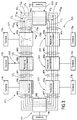
- FIG. 1 shows a local telecommunication network in RL rings according to the prior art.
- the local area network includes modules of connection M1 to M6 interconnected in series according to a duplicate structure ring by two sets of physical links, or transmission lines, unidirectional LP and LS.
- a ring is defined as a closed path to through connection modules, over which signals can flow.
- the LP connections constitute with the connection modules M1 to M6 a ring called "primary" AP
- the LS connections constitute with the M1 connection modules and M6 a ring called "secondary" AS.
- Telecommunication terminals T1 to T6 are respectively connected to connection modules M1 to M6 and can thus exchange data at through the RL network.
- the terminals T1 to T6 are for example stations or PC (Personal Computer) type computers.
- connection modules M1 to M6 are designed so that the direction of propagation of the signals circulating on the primary ring AP is opposite to the direction of propagation of the signals circulating on the secondary ring AS.
- the LP and LS connections are typically formed by pairs of wires metallic, coaxial cables or optical fibers.
- the local area network RL is for example a network conforming to the FDDI standard (Fiber Distributed Data Interface).
- the secondary ring AS is a spare ring which is used only when a breakdown, such as a line break or a failure of one of the connection modules, occurs in the network and causes an opening of the primary ring AP.
- An interconnection of the LAN network with another local network of the same type can also be carried out in a known manner.
- FIG. 2 shows a local telecommunication network RLa whose type of operation is used by the present invention.
- the local network RLa includes connection modules M1a to M6a for connecting terminals T1a to T6a to the network.
- the connection modules M1a to M6a are connected between them in series according to a ring structure by an integer N of sets of physical links L1 to LN.
- the links L1 to LN are lines of identical unidirectional transmission, for example with optical fiber, and constitute with the modules M1a to M6a N concentric rings, designated by A1 to AN.
- the integer N is greater than or equal to 2.
- connection module In the embodiment shown in FIG. 2, a single terminal is connected to each connection module. However, several terminals can be associated with a given connection module, as will be explained later in reference to figure 6.
- the local RLa network uses, in normal operation, several rings to ensure data exchange between terminals T1a to T6a. Signals travel in opposite directions on at least two of the N rings, for example rings A1 and A2, in order to authorize a loopback comparable to that described with reference to FIG. 1 in the event of a breakdown in the network.
- one of the N rings A1 to AN is previously selected according to a predetermined criterion.
- the selected ring is the one on which the space requirement is the least high when the data module M1a receives the data delivered by terminal T1a. Said data is then routed on the ring selected from the M1a connection module to the M5a connection, which transmits them to the T5a terminal.
- the selected ring is the one on which the way to go by the data from the first terminal to the second terminal is the shortest.
- the selected ring is the A2 ring since the data delivered by the terminal T1a only have to pass through three connection modules, namely the modules M1a, M6a and M5a, to reach the destination terminal T5a.
- the data exchanged in the RLa network is type data multimedia, and are thus representative of texts, voice signals and / or of images.
- the data exchange protocol used in the RLa network is by example an asynchronous ATM transfer type protocol (Asynchronous Transfer Mode).
- the data is then presented in the form of cells.
- the total transmission bit rate through the RLa network i.e. the total speed available for communications between terminals T1a to T6a, is equal to N times the bit rate on each of the rings A1 to AN, and therefore to N times the bit rate through the RL network of Figure 1. So, as part of a network ATM, the bit rate through the RLa network can reach approximately N ⁇ 155 Mbit / s.
- the local network RLa used in the invention is able to restore its continuity when one of the modules M1a to M6a fails or the transmission lines connecting two adjacent connection modules are broken (see reference CPa), by bringing the two rings A1 and A2 into contact respective points Aa, Ba and at respective points Ca, Da located on either side of the breakdown.
- communications between terminals T1a to T6a are routed only on the new ring formed by the parts of the rings A1 and A2 located respectively between points Aa and Ca and between points Ba and Da and opposed to the CPa failure.
- the bit rate through the RLa network during the failure is reduced compared to normal operation, and is equal to the bit rate of the ring A1 or A2.
- the total bit rate becomes again N times that of the ring A1 or A2.
- This ease of cutting the network can also be implemented to insert a new module without disturbing the operation of the other modules and therefore different connected terminals. Indeed, the opening of the network will be identified by the adjacent modules as a fault and to train accordingly automatic looping.
- FIG. 3 shows a local telecommunication network RLb conforming to the invention.
- the RLb network has a general ring configuration, and more precisely in concentric rings, and includes connection modules M1b to M8b to which respective terminals T1b to T8b are connected.
- connection modules M1b to M8b to which respective terminals T1b to T8b are connected.
- a single terminal is connected to each module connection.
- several terminals can be associated with a module given connection, as will be explained later with reference to the figure 6.
- the modules M1b to M8b are interconnected according to several structures in independent rings, also called subnets. Only three of these subnetworks, designated by ST1, ST2 and ST3, are represented in FIG. 3, for reasons of clarity.
- the first sub-network ST1 comprises the connection modules M1b, M3b and M6b, and an integer N1 of sets of unidirectional links L1 1 to L1 N1 connecting these modules together in series so as to constitute N1 rings A1 1 to A1 N1 .
- the second sub-network ST2 comprises the modules M2b, M5b and M7b, and an integer N2 of sets of unidirectional links L2 1 to L2 N2 connecting these modules together in series so as to form N2 rings A2 1 to A2 N2 .
- the third sub-network ST3 comprises the connection modules M4b and M8b, and an integer N3 of sets of unidirectional links L3 1 to L3 N3 connecting these modules together so as to constitute N3 rings A3 1 to A3 N3 .
- the integers N1, N2 and N3 are greater than or equal to 1. According to a typical embodiment of the present invention, these integers are equal to 2.
- the rings of a given sub-network pass directly through the connection modules of the other sub-networks.
- the data circulating on the links L1 1 to L1 N1 are analyzed and switched by the connection modules M1b, M3b and M6b of the first subnet ST1, but directly pass through the connection modules M2b, M5b and M7b of the second sub- ST2 network and the M4b and M8b connection modules of the third ST3 subnet.
- connection modules M2b, M5b and M7b of the second sub-network ST2 are analyzed and switched by the connection modules M2b, M5b and M7b of the second sub-network ST2, but pass directly through the connection modules M1b, M3b and M6b of the first ST2 subnet and the connection modules M4a and M8a of the third ST3 subnet.
- the data circulating on the links L3 1 to L3 N2 of the third subnet ST3 are analyzed and switched by the connection modules M4b and M8b of the third subnet ST3, but pass directly through the connection modules M1b, M3b and M6b of the first subnet ST1 and the connection modules M2b, M5b and M7b of the second subnet ST2.
- the subnets ST1 to ST3 are independent.
- the RLb network according to the invention is installed in a building which is shared by different companies, each company occupying part of the building.
- the RLb network subnets are then allocated respectively to said companies (three in number in the example corresponding to the realization of the figure 3).
- L1 1 to L1 N1 , L2 1 to L2 N2 , and L3 1 to L3 N3 are typically optical fibers.
- the physical links connecting two adjacent connection modules given Mib and Mi + 1b of the RLb network, where i is an integer between 1 and 7, are in the form of a sheet of optical fibers NPi.
- the NPi sheet is illustrated in more detail in Figure 4.
- the subnetworks ST1 to ST3 of the network RLa are "functionally" independent, but arranged according to a common structure composed of modules of connection M1b to M8b and of the optical fiber layers NP1 to NP8.
- one of the connection modules M1b to M8b includes a switching means, shown schematically in dotted lines in FIG. 3, to interconnect the subnets ST1 to ST3, i.e. to switch data between these subnets, or interconnect only two of these subnets.
- the switching means is described in more detail below. description.
- each subnet ST1 to ST3 operates in the same way as the network RLa described previously with reference to FIG. 2, and routes multimedia type data according to the ATM protocol for example.
- the subnet ST1 to transmit data through the subnet ST1 from the terminal T1b connected to the connection module M1b to the terminal T6b connected to the connection module M6b, one of the rings A1 1 to A1 N1 is selected according to the criterion predetermined size of rings or shortest path as defined above.
- connection modules of the subnet ST1 for example the modules M1b, M3b and M6b, where it is analyzed, and passes directly through connection modules of other subnets, namely in this case the M2b, M4b and M5b modules.
- each subnet ST1 to ST3 comprises at least two rings transmitting signals in opposite directions. So in the event of a breakdown on one of the subnets, the same operations as in the RLa network are implemented to restore continuity of the subnetwork.
- At least one of the subnetworks ST1 to ST3 has a single ring, or works in the same way as the network double ring RL of figure 1.
- FIG. 5 shows a local telecommunication network RLc according to a another embodiment of the invention.
- the RLc network includes modules M1c to M6c interconnected to form two subnetworks in double ring of the type of the sub-networks ST1 to ST3 of FIG. 3.
- the network RLc further comprises a switching means, shown diagrammatically dotted in the M5c module, to interconnect the RLc network with another RLT ring network including M7c and M8c connection modules.
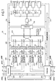
- FIG. 6 shows in detail a connection module 10 of the type of modules M1a to M6a of the RLa network of FIG. 2, modules M1b to M8b of the RLb network of Figure 3, or modules M1c to M6c of the RLc network of figure 5.
- connection module 10 is coupled via connectors 101, 102 respectively with two links LI1, LI2 of a first ring AN1 and respectively to two links LI3, LI4 of a second ring AN2.
- the LI1 to LI4 links are unidirectional fiber transmission lines optical.
- the connection module 10 further comprises other connectors 103 to 107 to which respective terminals TR1 to TR5 are connected, a sub-module transceiver 108, a switching submodule 109 and a user interface sub-module 110.
- the three sub-modules 108, 109 and 110 are powered by a power supply 111 and are connected to each other by internal connectors 112, 113 and 114 of the flat connector type.
- the use of internal connectors 112, 113 and 114 allows the possible replacement of a submodule 108, 109 or 110 in connection module 10.
- the role of the transmit-receive sub-module 108 is to transmit to the connection modules adjacent to module 10 in the signal network digital data supplied by the switching sub-module 109, and receive and regenerate digital data signals transmitted over links LI2 and LI3.
- the transmission-reception sub-module 108 includes transmission means 115, 116, reception means 117, 118, and modems 119, 120.
- the transmission 115 and reception 117 means are connected respectively to the links LI1 and LI3 through the connector 101.
- the means 116 and 118 receive are connected to LI4 and LI2 through the connector 102.
- the modem 119 is connected to the transmission means 115 and reception 117, and to the switching submodule 109 through the internal connector 112.
- the modem 120 is connected to the transmission means 116 and reception 118, and to the switching sub-module 109 through the connector internal 113.
- the transmission means 115, 116 and reception 117, 118 are diodes laser and photodetectors respectively, operating at one wavelength about 850 nm.
- the laser diodes and the photodetectors can be type of those conventionally used in optical disc drives.
- the switching sub-module 109 switches to the transmission means 115, 116 of the digital data supplied by the interface sub-module user 110 or the transmit-receive sub-module 108.
- the sub-module of switching 109 essentially includes a switching circuit 121 and a control circuit 122.
- the switching circuit 121 is connected to the modems 119, 120 respectively through connectors 112, 113, and to the submodule user interface 110 through connector 114.
- the control circuit 122 controls the switching circuit 121 and also has a role network administration, to manage breakdowns in particular.
- Circuit 122 is preferably a CPU (Central Processing Unit) type microprocessor.
- the user interface sub-module 110 provides the interface between the circuits using network protocol and TR1 to TR5 terminals using each a protocol of their own.
- the user interface sub-module 110 includes a multiplexer / demultiplexer 123 and conversion circuits protocol 124-1 to 124-5 associated respectively with terminals TR1 to TR5.
- the TR1 to TR5 terminals can be of different types.
- the terminal TR1 is a computer terminal, the TR2 terminal a telephone terminal, the TR3 terminal a building management terminal managing a sensor system such an alarm system, etc ...
- the DN1 data delivered by the terminal TR1 and supplied to the user interface sub-module 110 through the connector 103 are converted by the circuit 124-1 according to the protocol used in the network, for example the ATM protocol.
- the converted DN2 data, organized in the form of cells, are applied to the multiplexer / demultiplexer 123 where they are multiplexed with other data DN2 ', DN2''possibly produced simultaneously by other terminals TR2, TR3 and converted by the circuits of associated conversion 124-2, 124-3.
- the multiplexed data DN3 at the output of the multiplexer / demultiplexer 123 are transmitted through the connector 114 to an input port el of the switching circuit 121.
- the circuit 121 selects a ring from the rings AN1 and AN2 according to one of the predetermined criteria ring space or shortest path defined above, for DN2 data from the TR1 terminal and contained in the DN3 multiplexed data, as well as for the DN2 data , DN2 from other terminals TR2, TR3.
- the switching circuit 121 directs the received DN2 data, contained in the multiplexed data DN3, to the transmission means 115, 116 corresponding to the ring AN1, AN2 selected for the data DN2, through the connector 112, 113 and the modem 119, 120 and from a corresponding output port s1, s2.
- the laser diode 115, 116 emits a digital optical signal SE1, SE2 in response to the reception of the data signal DN2 modulated by the modem 119, 120.
- the same operations as above are implemented for the data DN2 and DN2 also contained in the DN3 data and coming from the other terminals TR2, TR3.
- the photodetectors 117, 118 convert signals digital optics SR2, SR1, received from links LI3, LI1 from rings AN2, AN1 respectively, in electrical signals Sel2, Sel1.
- the signals Sel2, Sel1 are demodulated and re-shaped by modems 119 and 120 and transmitted through connectors 112, 113 to input ports e2 and e3 of the switching circuit 121.
- the switching circuit 121 reads the addresses of destination terminal in each cell of signals Sel2, Sel1.
- Cells from each LI2, LI3 link and for which the recipient address designates a terminal other than TR1 to TR5 terminals connected to module 10 are retransmitted from the output access s1, s2 to the link LI1, LI4 respectively through connector 112, 113, modem 119, 120 and the medium 115, 116.
- the other cells, for which the recipient address designates one of the terminals TR1 to TR5 are directed from an output port s3 to the multiplexer / demultiplexer 123 through the connector 114.
- the multiplexer / demultiplexer 123 demultiplexes the received cells and the needle to terminals TR1 to TR5 according to the destination terminal addresses included in them.
- the conversion circuits 124-1 to 124-5 convert the data provided by circuit 123 according to the associated protocol (s) respectively at the destination terminals.
- the sub-module transceiver 108 further includes an integer M greater than or equal to 1 of internal links 125-1 to 125-M directly connecting the connectors 101 and 102.
- Internal connections 125-1 to 125-M ensure continuity of M rings AN-1 to AN-M belonging to subnets other than that of connection module 10, so that the signals flowing on the rings AN-1 to AN-M pass directly through module 10, i.e. do not pass to through switching circuit 121 in module 10.
- Internal connections 125-1 to 125-M may, however, pass between connectors 101 and 102 amplifiers or signal regeneration circuits (not shown) for amplify or regenerate, in module 10, the signals circulating on the rings AN-1 to AN-M.
- some of the terminals TR1 and TR5 are capable of producing and receiving data according to the network protocol. Their associated conversion circuits 124-1 to 124-5 are then deleted.
- the links LI1 to LI4 of the rings AN1 and AN2 consist of pairs of metal wires or coaxial cables.
- the transmission means 115, 116 and reception 117, 118 are then amplifiers.
- connection module 10 in the example illustrated in the Figure 6, is intended to be integrated into a network or sub-network with two rings AN1, AN2. This structure can easily be generalized to a larger number of rings, not necessarily even.
- a transmission means To each of the rings of the network or sub-network, are then associated a transmission means, a reception means and a modem in the transceiver submodule, and input and output in the switching circuit.
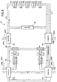
- FIG. 7 shows a connection module 20 according to the invention, according to a second exemplary embodiment.
- the connection module 20 is coupled on two sides opposite to links of four rings ANN1 and ANN4 by through connectors 201 and 202, and includes connectors 203 through 207 to which terminals (not shown) are connected.
- Module 20 includes in addition to a transmit-receive submodule 208, a switching submodule 209, and a user interface submodule 210.
- the submodules 208, 209 and 210 are all three powered by a power supply 211 and are connected between them by internal connectors 212 to 216.
- the transmitting-receiving sub-module 208 includes four arrangements transmission-reception elements identical to arrangements 115-117-119 and 116-118-120 of Figure 6. Each arrangement is constituted by a transmission means 217 to 220, reception means 221 to 224, and a modem 225 to 228.
- the first arrangement 217-221-225 and the second arrangement 218-222-226 are coupled respectively to two pairs of links of the rings ANN1 to ANN4 by the connector 201.
- the third arrangement 219-223-227 and the fourth arrangement 220-224-228 are coupled respectively to two other pairs of connections of the rings ANN1 to ANN4 by the connector 202.
- the switching submodule 209 includes a switching circuit 229 controlled by a control circuit 230.
- Four input ports e1 to e4 of the switching circuit 229 are respectively connected to the reception means 221 to 224 through the modems 225 to 228 and the internal connectors 212 to 215.
- Four output ports s1 at s4 of the switching circuit 229 are respectively connected to the transmission means 217 to 220 through the modems 225 to 228 and the internal connectors 212 to 215.
- a fifth output port s5 'and a fifth input port e5' of the circuit 229 switches are connected to the user interface submodule 210 through the connector 216.
- User interface submodule 210 is identical to submodule 110 of FIG. 6, and comprises a multiplexer / demultiplexer 231 and circuits protocol conversion 232-1 to 232-5.
- connection module 20 this the latter is used in a network or sub-network with four rings of the type respectively of the RLa network shown in FIG. 2 or of the subnets ST1 to ST3 of Figure 3, and performs operations comparable to those of module 10 (figure 6).
- the switching circuit 229 selects one of the rings ANN1 to ANN4 to transmit data from a first terminal connected to the module to a second terminal connected to another module.
- internal links 232 are provided to directly connect connectors 201 and 202 and ensure the continuity of rings of other subnets.
- connection module 20 this the latter is used in a four-ring network or subnets, but in which only the first two rings are used to transmit data in normal operation, the other two rings serving as rescue in case of failure on the first two rings. So in operation normal, the connection module 20 performs the same operations as the module 10 of FIG. 6 using the first and fourth arrangements 217-221-225 and 220-224-228 to transmit and receive data on the rings ANN1 and ANN2 of the network. In the event of a failure on rings ANN1, ANN2, all the signals that must initially be transmitted on these by the module connection 20 are switched by switching circuit 229 to the emergency rings ANN3 and ANN4 respectively through the second and third arrangements 218-222-226 and 219-223-227.
- connection module 20 this last one is of the type of module M3b in figure 3, i.e. module 20 is capable of interconnecting two subnets including the pairs of rings ANN1-ANN2 and ANN3-ANN4 respectively.
- a switching of data to be transmitted on either of the two subnets is performed by switching circuit 229, as a function of the addresses of the cells of data supplied by the user interface sub-module 210 to the access input e5 'of circuit 229 and the addresses of the data cells received from rings ANN1 to ANN4 by the sub-module 208.
- FIG. 8 schematically shows a connection module 30 according to the invention, according to a third embodiment.
- Module 30 notably includes connectors 301, 302 for coupling the module to ring links ANN1 ', ANN2' of a first subnet, connectors 303 to 307 to connect respective terminals (not shown) to module 30, a transmit-receive submodule 308, switching submodule 309, un user interface sub-module 310 and a power supply unit 311.
- the sub-modules 308 and 310 are respectively of the type of sub-modules 108 and 110 of Figure 6.
- connection module 30 further comprises two connectors 312 and 313 connected to the switching sub-module 309 to couple the module 30 to ring links ANN3 ', ANN4' of a second sub-network.
- the sub-module switch 309 provides interconnection between first and second subnets aforementioned in a manner comparable to that described above with reference to FIG. 7, as well as the transmission-reception of the signals on the rings ANN3 ′ and ANN4 '.
- the present invention has been described by way of example only for a ATM type network protocol.
- any other protocol such as IP (Internet Protocol) or IPX (registered trademarks) protocols, can be used in the present invention.
- IP Internet Protocol
- IPX registered trademarks
Landscapes
- Engineering & Computer Science (AREA)
- Computer Networks & Wireless Communication (AREA)
- Small-Scale Networks (AREA)
Priority Applications (1)
| Application Number | Priority Date | Filing Date | Title |
|---|---|---|---|
| EP98402366A EP0989702A1 (de) | 1998-09-25 | 1998-09-25 | Lokales Telekommunikationsnetzwerk |
Applications Claiming Priority (1)
| Application Number | Priority Date | Filing Date | Title |
|---|---|---|---|
| EP98402366A EP0989702A1 (de) | 1998-09-25 | 1998-09-25 | Lokales Telekommunikationsnetzwerk |
Publications (1)
| Publication Number | Publication Date |
|---|---|
| EP0989702A1 true EP0989702A1 (de) | 2000-03-29 |
Family
ID=8235495
Family Applications (1)
| Application Number | Title | Priority Date | Filing Date |
|---|---|---|---|
| EP98402366A Withdrawn EP0989702A1 (de) | 1998-09-25 | 1998-09-25 | Lokales Telekommunikationsnetzwerk |
Country Status (1)
| Country | Link |
|---|---|
| EP (1) | EP0989702A1 (de) |
Citations (6)
| Publication number | Priority date | Publication date | Assignee | Title |
|---|---|---|---|---|
| GB2138651A (en) * | 1983-04-21 | 1984-10-24 | Standard Telephones Cables Ltd | Local Area Networks Comprised of Interconnected Sub Networks |
| EP0472296A1 (de) * | 1990-08-02 | 1992-02-26 | AT&T Corp. | Paketvermittlungs-, Wellenlängenmultiplex-Ringnetz hoher Leistung mit Wellenlängen Abstimmbaren Lasern |
| US5299312A (en) * | 1990-11-15 | 1994-03-29 | Massachusetts Institute Of Technology | Network fault recovery by controllable switching of subnetworks |
| EP0645905A2 (de) * | 1993-09-24 | 1995-03-29 | Nec Corporation | Verfahren zur Verwaltung von Teilnetzwerken eines SONET-Rings |
| EP0765051A2 (de) * | 1995-09-19 | 1997-03-26 | AT&T Corp. | Schrittweise erweiterbare Ringarchitektur zur Bereitstellung von Telefondiensten |
| WO1998025365A2 (en) * | 1996-12-06 | 1998-06-11 | Bell Communications Research, Inc. | Inter-ring cross-connect for survivable multi-wavelength optical communication networks |
-
1998
- 1998-09-25 EP EP98402366A patent/EP0989702A1/de not_active Withdrawn
Patent Citations (6)
| Publication number | Priority date | Publication date | Assignee | Title |
|---|---|---|---|---|
| GB2138651A (en) * | 1983-04-21 | 1984-10-24 | Standard Telephones Cables Ltd | Local Area Networks Comprised of Interconnected Sub Networks |
| EP0472296A1 (de) * | 1990-08-02 | 1992-02-26 | AT&T Corp. | Paketvermittlungs-, Wellenlängenmultiplex-Ringnetz hoher Leistung mit Wellenlängen Abstimmbaren Lasern |
| US5299312A (en) * | 1990-11-15 | 1994-03-29 | Massachusetts Institute Of Technology | Network fault recovery by controllable switching of subnetworks |
| EP0645905A2 (de) * | 1993-09-24 | 1995-03-29 | Nec Corporation | Verfahren zur Verwaltung von Teilnetzwerken eines SONET-Rings |
| EP0765051A2 (de) * | 1995-09-19 | 1997-03-26 | AT&T Corp. | Schrittweise erweiterbare Ringarchitektur zur Bereitstellung von Telefondiensten |
| WO1998025365A2 (en) * | 1996-12-06 | 1998-06-11 | Bell Communications Research, Inc. | Inter-ring cross-connect for survivable multi-wavelength optical communication networks |
Similar Documents
| Publication | Publication Date | Title |
|---|---|---|
| US4866704A (en) | Fiber optic voice/data network | |
| EP2320603B1 (de) | Kommunikationssystem in einem flugzeug | |
| EP0082037B1 (de) | Digitales System mit optischer Nachrichtenübertragung | |
| EP0579529B1 (de) | Vorrichtung zum Verbinden eines Terminals an ein mindestens aus einem Ring bestehendes lokales Netz | |
| Norris | Gigabit ethernet technology and applications | |
| EP0715437A1 (de) | Weglenkungsverfahren für ATM-Netz | |
| EP0446827A1 (de) | Terminaleinrichtung für asynchrones Netzwerk | |
| FR2710167A1 (fr) | Dispositf de commutation d'unités de protocole à haut débit, et procédé de commutation correspondant. | |
| US7321981B1 (en) | Multi-port line card redundancy technique for an intermediate network node | |
| WO2004056049A1 (fr) | Reseau ethernet en double anneau | |
| EP1494383B1 (de) | Optisches WDM Ringnetzwerk zur durch lokale Zustandsschaltung gesicherten Signalübertragung bei Erfassung einer lokalen Unterbrechung | |
| EP0989702A1 (de) | Lokales Telekommunikationsnetzwerk | |
| FR2768579A1 (fr) | Reseau local de telecommunication | |
| FR2534753A1 (fr) | Systeme d'etablissement de circuits de transmission de donnees a debit constant entre une pluralite de stations | |
| EP3666620B1 (de) | Zugverband und entsprechendes schienenfahrzeug | |
| FR2767242A1 (fr) | Dispositif et procede de commutation de cellules atm a groupes de connexions, et fonctions terminales d'entree et de sortie correspondantes | |
| EP0720331A1 (de) | Anordnung zur Verkettung von Zwischenmodulen, insbesondere Relaisstationen und damit ausgerüstete Einrichtung | |
| US9021130B1 (en) | Photonic line sharing for high-speed routers | |
| FR2570233A1 (fr) | Reseau numerique asynchrone | |
| EP0384847A1 (de) | Verfahren und Vorrichtung zum Zugriff auf ein erweitertes Netz | |
| EP0471633A1 (de) | Kommunikationsnetz mit Schreib- und Lesering, und Zugriffs- und Rekonfigurationsverfahren eines solchen Netzes | |
| EP0999720A1 (de) | Vorrichtung zur Durchschaltvermittlung in einem Telekommunikationsnetzwerk | |
| Zobrist | Local area networks | |
| EP1376910A2 (de) | Optisches Ringnetzwerk mit abgekoppelten Lese- und Schreibfasern | |
| Anidi et al. | Storage area networking–an introduction and future development trends |
Legal Events
| Date | Code | Title | Description |
|---|---|---|---|
| PUAI | Public reference made under article 153(3) epc to a published international application that has entered the european phase |
Free format text: ORIGINAL CODE: 0009012 |
|
| AK | Designated contracting states |
Kind code of ref document: A1 Designated state(s): DE ES FR GB IT |
|
| AX | Request for extension of the european patent |
Free format text: AL;LT;LV;MK;RO;SI |
|
| 17P | Request for examination filed |
Effective date: 20000927 |
|
| AKX | Designation fees paid |
Free format text: DE ES FR GB IT |
|
| STAA | Information on the status of an ep patent application or granted ep patent |
Free format text: STATUS: THE APPLICATION IS DEEMED TO BE WITHDRAWN |
|
| 18D | Application deemed to be withdrawn |
Effective date: 20040401 |