EP0715437A1 - Weglenkungsverfahren für ATM-Netz - Google Patents
Weglenkungsverfahren für ATM-Netz Download PDFInfo
- Publication number
- EP0715437A1 EP0715437A1 EP95402660A EP95402660A EP0715437A1 EP 0715437 A1 EP0715437 A1 EP 0715437A1 EP 95402660 A EP95402660 A EP 95402660A EP 95402660 A EP95402660 A EP 95402660A EP 0715437 A1 EP0715437 A1 EP 0715437A1
- Authority
- EP
- European Patent Office
- Prior art keywords
- switches
- cells
- input
- sub
- output
- Prior art date
- Legal status (The legal status is an assumption and is not a legal conclusion. Google has not performed a legal analysis and makes no representation as to the accuracy of the status listed.)
- Withdrawn
Links
Images


Classifications
-
- H—ELECTRICITY
- H04—ELECTRIC COMMUNICATION TECHNIQUE
- H04L—TRANSMISSION OF DIGITAL INFORMATION, e.g. TELEGRAPHIC COMMUNICATION
- H04L45/00—Routing or path finding of packets in data switching networks
- H04L45/24—Multipath
-
- H—ELECTRICITY
- H04—ELECTRIC COMMUNICATION TECHNIQUE
- H04L—TRANSMISSION OF DIGITAL INFORMATION, e.g. TELEGRAPHIC COMMUNICATION
- H04L45/00—Routing or path finding of packets in data switching networks
- H04L45/02—Topology update or discovery
- H04L45/10—Routing in connection-oriented networks, e.g. X.25 or ATM
Definitions
- the field of the invention is that of switching networks with asynchronous time division multiplexing, such as, in particular, networks supporting ATM cell traffic (Asynchronous Transfer Mode in English).
- the invention relates to the routing (or routing) of cells in such a switching network with asynchronous time division multiplexing.
- a switching network makes it possible to interconnect input switches and output switches by means of switches.
- a sequence of cells belonging to a given communication must be able to be transmitted between any of the input switches and any of the output switches.
- each of the input switches can be connected to each of the output switches by at least two separate paths, each path corresponding to a distinct series of switches.
- Each switch includes at least two inputs and at least two outputs, and is designed to transfer to one of its outputs a cell received on one of its inputs.
- a first known mode of routing consists in defining a single path for the series of cells to be transmitted belonging to a given communication. Thus, after a communication establishment phase (during which the path is determined), all the cells pass successively through this single path.
- This first known mode of routing has the advantage of requiring the search (and then the use) of only one path. However, finding that one path can be problematic. In fact, it may be that during the communication establishment phase, no path can be found when the switching network is not saturated.
- This situation called blocking in the broad sense, therefore corresponds to the case where, although an input switch and an output switch are available, the routing mode chosen is such that there is no series of switches allowing them to be interconnected. It should be noted that a blocking situation in the strict sense corresponds to the case where there is no possible path between an input switch and an output switch, regardless of the routing mode chosen.
- a known solution consists in carrying out a spatial expansion (increase in the number of switches in the network and / or an increase in speed), which increases the cost and the complexity of the network.
- Another known solution consists in rearranging the paths associated with the communications already established, so as to make certain switches available and allow the development of a path. Such a rearrangement of the paths is a complex operation, or even impossible if there are several simultaneous blockings.
- a second known mode of routing consists in transmitting in a decorrelated manner the cells of the same sequence belonging to a given communication.
- the successive cells of the same sequence take different paths (we also speak of multi-path mode).
- the assignment of a path to a cell is generally carried out according to a random distribution.
- the number of different paths is arbitrary, and generally limited to the minimum number necessary.
- multi-path networks In order to avoid bottlenecks, so-called multi-path networks generally include a cell mixing stage. Unfortunately, such a patching stage does not make it possible to control the differences in flow rates arriving on the various input switches.
- the invention particularly aims to overcome these various drawbacks of the state of the art.
- one of the objectives of the present invention is to provide a method of routing cells in an asynchronous time-division multiplex switching network, which offers a non-blocking situation in the broad sense of the network without requiring spatial expansion. (increase in the number of matrices) or expansion of the network speed until it is saturated.
- an objective of the invention is to avoid clogging of the buffer memories of the switches.
- Another objective of the invention is to provide such a routing method which does not require the complex implementation of a random distribution of the cells on different paths.
- the routing method of the invention consists, for each series of cells to be transmitted, to determine all the possible paths, to establish a sub-connection for each of the possible paths, and to systematically and in turn assign role one of the sub-connections to each cell.
- each of the N sub-connections originating from an input switch for a given communication supports 1 / N of the traffic arriving on this input switch.
- said distribution is cyclical.
- the distribution of the invention ensures an equitable distribution of traffic on the network, which limits the risks of clogging of the buffers of the switches, and allows the non-blocking (in the broad sense) of the network.
- each of said input switches is associated with a switch belonging to a first stage
- each of said output switches is associated with a switch belonging to a last stage
- the switches of said first and last stages being interconnected by means of at least two switches forming at least one intermediate stage, the number of possible paths corresponding to the number of switches assigned to cell transfer and belonging to said intermediate stage or to the product of numbers of switches assigned to cell transfer and belonging to each of said intermediate stages.
- the central floor constitutes the only floor intermediate.
- the routing method of the invention makes it possible to halve, compared to the solution without blocking in the strict sense, the number of switches per access.
- each of said switches is duplicated, so as to ensure in parallel a double transmission of each of said cells.
- the cells received in parallel are compared.
- the network is duplicated in two branches (or planes), each branch being a switching network with asynchronous time division multiplexing, which provides good tolerance for failures or transmission errors.
- each of said cells is assigned error detection and / or correction data, and, on reception, the quality of the cells received is checked in parallel, and those with the best quality are selected to reconstruct said sequence. .
- the network is thus able to withstand multiple errors or failures, until a matrix in one branch and its duplicate in the other branch are simultaneously down.
- the location of a faulty matrix in a branch is facilitated by knowing the path taken by a disturbed cell having crossed this faulty matrix.
- each of said input switches also comprises a modulo N counter, incremented for each new cell to be transmitted from said cell, said allocation means assigning one of said sub-connections to each cell of said sequence according to the value entered in said counter.
- the invention also relates to the input switch as such of a network of the type described above, as well as the applications of the method presented above.
- the invention therefore relates to a method for routing cells in an asynchronous time division multiplex switching network.
- asynchronous transfer mode (ATM, for Asynchronous Transfer Mode in English)
- the cells which constitute the data units, have a fixed and short structure and follow each other without absolute position reference.
- the identification of the communication channel is indeed carried by the cell itself, in a header. Consequently, a source can emit cells at its own rate, without direct reference to the communication network to which it is connected.
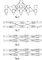
- FIG. 1 schematically presents an example of a switching network in which the cell routing method of the invention can be implemented.
- This network interconnects input ports ME1 to ME4 and output ports MS1 to MS4 via intermediate switches M1 to M8. Subsequently, it is considered that said ports are switches, or matrices.
- Each associated input switch ME1 to ME4 can be connected to each of the associated output switches MS1 to MS4 by at least two paths, each path corresponding to a distinct series of switches M1 to M8.
- a series of switches defining a path is in fact made up of a single switch M1 to M8.
- Each intermediate switch M1 to M8 comprises at least two inputs and at least two outputs and is designed to transfer to one of its outputs a cell received on one of its inputs.
- the network mesh has not been represented, that is to say all the permanent links existing on the one hand between the outputs of the input switches ME1 and ME4 and the inputs of intermediate switches M1 to M8, and on the other hand between the outputs of intermediate switches M1 to M8 and the inputs of output switches MS1 to MS4.
- a sub-connection is a virtual conduit to which certain cells of the same communication are directed, according to a systematic and cyclical distribution.
- a sub-connection is generally only defined for the duration of this communication.
- FIG. 1 we consider by way of example the case where it is desired to transmit a series of cells between the input switch ME1 and the output switch MS3.
- the census step makes it possible to establish 8 possible paths between ME1 and MS3, each path corresponding to the passage by one of the eight intermediate switches M1 to M8.
- the next step is to establish 8 sub-connections SC0 to SC7 corresponding to the 8 possible paths.
- the step of distributing the cells to the sub-connections is illustrated in FIG. 2.
- the first sub-connection SC0 receives cells C1 and C9; the second sub-connection SC1 receives cells C2 and C10; the third sub-connection SC2 receives cells C3 and C11; etc ...
- each sub-connection receives all the cells which, modulo N, have the same serial number in the following, with N the total number of established sub-connections.
- each input switch ME1 to ME4 is associated with a switch belonging to a first stage
- each output switch is associated with a switch belonging to a last stage
- these switches of the first and last stages are interconnected by means of at least two switches forming at least one intermediate stage.
- the number N of possible paths between an input switch and an output switch is a function of the number of switches belonging to the intermediate stage or stages and which are assigned to the cell transfer.
- N k
- Each input switch ME1, ME2 has two inputs A, B and C, D respectively and two outputs. Each of the two outputs of an input switch ME1, ME2 is connected to an input of each of the two switches M1, M2. Each of the two outputs of a switch M1, M2 is connected to an input of each of the two output switches MS1, MS2. Each output switch MS 1, MS2 has two outputs X, Y and Z, T respectively.
- this blocking situation is avoided. Indeed, for each communication arriving on an input A, B, C, D of input switch ME1, ME2, as many sub-connections are established as there are switches M1, M2 in the single intermediate stage (i.e. two sub-connections in this example).
- the flow arriving on each input A, B, C, D is distributed over several (two in this example) sub-connections, the cells arriving on an input being distributed systematically and cyclically to the different sub-connections corresponding to the different paths.
- each sub-connection carries half of the initial speed and the same link can therefore support two sub-connections allowing the transmission of cells belonging to two separate communications.
- the link between the input switch ME1 and the switch M1 supports a sub-connection connecting the input A to the output T and a sub-connection connecting the input B to the output Y.
- each of the switches is duplicated and the network consists of two identical branches (or planes) 81, 82.
- Each cell to be transmitted 83 is also duplicated (84), the two cells obtained 85, 86 being transmitted in parallel in the two planes 81, 82.
- a cell 810 is selected (after comparison) (89) from two cells received 87, 88.
- each cell to be transmitted 83 an error detection and / or correction data item (CRC byte for example).
- CRC byte for example
- the most probable cell 810 is selected (89) as a function of the error detection and / or correction data.
- the network input switches perform a cellulization function and the network output switches a decellulization.
- the network input switches receive byte frames and the network output switches also generate byte frames.
- the input switches make it possible to pass from a synchronous transmission mode to an asynchronous transmission mode, the output switches allowing the reverse passage.
- FIG. 9 presents a diagram of a particular embodiment of a network input switch 91 according to the invention, of the type receiving data frames on input links 92 1 to 92 3 and generating cells data on output links 93 1 to 93 2 .
- the input links 92 1 , 92 2 are for example synchronous links at 155.52 Mbit / s carrying frames of the STM1 type.
- the output links 93 1 , 93 2 are for example asynchronous links at 622 Mbit / s each corresponding to an access to one of the two branches of an ATM network, as will be explained below.
- Each input link 92 1 , 92 2 and each output link 93 1 , 93 2 corresponds to line end equipment 94 1 , 94 2 , 95 1 , 95 2 .
- the STM1 frames received on the input links 94 , 92 2 are transformed into data cells in a cellulizer 96 (presented below in connection with FIG. 10).
- a cellulizer 96 presents below in connection with FIG. 10.
- Each cell emitted by the cellulizer 96 is duplicated in a duplication module 97 (QRP component operating in IEM mode for example) and the two cells obtained are each directed to one of the two output links 93 1 , 93 2 .
- the routing method implemented in this particular embodiment of the invention is therefore of the type presented previously in relation to FIG. 8. for each sequence of cells generated by the cellulizer, two identical sequences of cells will be transmitted in two parallel network plans which each constitute an asynchronous time division multiplex switching network implementing the routing method of the invention with in particular the establishment of N sub-connections corresponding to the N possible paths, and the systematic and cyclic distribution cells to the N sub-connections).
- FIG. 10 presents a diagram of a particular embodiment of the cellulizer 96 included in the input switch 91 of FIG. 9.
- a cellulizer 96 is associated with each input link 92 1 , 92 2. This cellulizer receives, after synchronization of the incoming frames, a succession of bytes 101.
- Two registers 102, 103 successively receive each byte and its corresponding number in the frame.
- this buffer register 106 When this buffer register 106 is full, it is copied into the data field 104 of a cell 105.
- the C1 bytes intended for the same cell also make it possible to calculate a CRC data item for detection and / or correction of errors.
- This CRC data is stored in a buffer register 108, then written, with the frame number, in a buffer register 109 AAL (ATM adaptation layer).
- this buffer register 109 being copied into an AAL field 1010 of each cell 105.
- each group x there are d different sub-connections under which are successively and cyclically distributed the successive cells of the same sequence (for example associated with a given communication).
- FIG. 11 presents a diagram of an embodiment of a network output switch 110 according to the invention, of the type generating data frames on output links 112 1 , 112 2 from sequences of cells of data received from links input 111 1 , 111 2 .
- the output switch 112 1 , 112 2 is for example a synchronous link at 155.52 Mbit / s carrying frames of the STM1 type.
- Each cell 113 received on an input link 111 1 is temporarily stored in a buffer register. Depending on the ICI and the frame number, the useful data field and the CRC are written in the degig memory 114 associated with this input link 111 1 .
- the useful data field and the CRC of the corresponding cell received on the other input link 111 2 are stored in the clearing memory associated with this other input link 111 2 .
- the de-icing is carried out in each memory by reserving a place per cell expected. In this way, resequencing is automatically ensured, and the detection of missing cells is immediate.
Applications Claiming Priority (2)
| Application Number | Priority Date | Filing Date | Title |
|---|---|---|---|
| FR9414451A FR2727818B1 (fr) | 1994-12-01 | 1994-12-01 | Procede d'acheminement de cellules dans un reseau de commutation a multiplexage temporel asynchrone, reseau, commutateur d'entree et application correspondants |
| FR9414451 | 1994-12-01 |
Publications (1)
| Publication Number | Publication Date |
|---|---|
| EP0715437A1 true EP0715437A1 (de) | 1996-06-05 |
Family
ID=9469376
Family Applications (1)
| Application Number | Title | Priority Date | Filing Date |
|---|---|---|---|
| EP95402660A Withdrawn EP0715437A1 (de) | 1994-12-01 | 1995-11-27 | Weglenkungsverfahren für ATM-Netz |
Country Status (6)
| Country | Link |
|---|---|
| US (1) | US5712854A (de) |
| EP (1) | EP0715437A1 (de) |
| JP (1) | JPH08237280A (de) |
| CN (1) | CN1129377A (de) |
| CA (1) | CA2163929A1 (de) |
| FR (1) | FR2727818B1 (de) |
Families Citing this family (15)
| Publication number | Priority date | Publication date | Assignee | Title |
|---|---|---|---|---|
| US6226687B1 (en) * | 1996-09-05 | 2001-05-01 | Nortel Networks Limited | Method and apparatus for maintaining an order of data packets |
| US6118763A (en) * | 1996-09-27 | 2000-09-12 | Inventions, Inc. | Transmission of voice over an asynchronous network |
| US5940403A (en) * | 1996-11-07 | 1999-08-17 | Adtran, Inc. | Quarter-rate 2B1Q ISDN architecture with embedded differential delay compensation for extending range of DDS communications |
| JP2950369B2 (ja) * | 1996-12-27 | 1999-09-20 | 日本電気株式会社 | Atm網における現用予備経路設定方式 |
| US6307852B1 (en) * | 1998-04-09 | 2001-10-23 | Nortel Networks Limited | Rotator switch data path structures |
| US6330221B1 (en) * | 1998-06-18 | 2001-12-11 | Cisco Technology, Inc. | Failure tolerant high density dial router |
| US6351454B1 (en) * | 1998-07-24 | 2002-02-26 | Cisco Technology, Inc. | Apparatus and method for maintaining packet ordering over parallel links of a crossbar based switch fabric |
| US6643260B1 (en) | 1998-12-18 | 2003-11-04 | Cisco Technology, Inc. | Method and apparatus for implementing a quality of service policy in a data communications network |
| US6625161B1 (en) | 1999-12-14 | 2003-09-23 | Fujitsu Limited | Adaptive inverse multiplexing method and system |
| US6798746B1 (en) | 1999-12-18 | 2004-09-28 | Cisco Technology, Inc. | Method and apparatus for implementing a quality of service policy in a data communications network |
| US6952419B1 (en) * | 2000-10-25 | 2005-10-04 | Sun Microsystems, Inc. | High performance transmission link and interconnect |
| US7095741B1 (en) * | 2000-12-20 | 2006-08-22 | Cisco Technology, Inc. | Port isolation for restricting traffic flow on layer 2 switches |
| US7257629B2 (en) * | 2001-09-27 | 2007-08-14 | Siemens Communications, Inc. | Method and apparatus for providing back-up capability in a communication system |
| CA2357931A1 (en) * | 2001-09-27 | 2003-03-27 | Alcatel Canada Inc. | System and method of selecting sources for a network element having redundant sources |
| CA2556420A1 (en) * | 2004-02-19 | 2005-09-01 | Georgia Tech Research Corporation | Systems and methods for parallel communication |
Citations (2)
| Publication number | Priority date | Publication date | Assignee | Title |
|---|---|---|---|---|
| EP0529283A1 (de) * | 1991-08-27 | 1993-03-03 | Siemens Aktiengesellschaft | Verfahren zur Bitfehlerreduktion in digitalen Kommunikationssystemen |
| US5355372A (en) * | 1992-08-19 | 1994-10-11 | Nec Usa, Inc. | Threshold-based load balancing in ATM switches with parallel switch planes related applications |
Family Cites Families (6)
| Publication number | Priority date | Publication date | Assignee | Title |
|---|---|---|---|---|
| US4383316A (en) * | 1980-04-14 | 1983-05-10 | Bell Telephone Laboratories, Incorporated | Apparatus for and method of collating partitioned time disordered synchronous data streams |
| USH1175H (en) * | 1988-05-04 | 1993-04-06 | The United States Of America As Represented By The Secretary Of The Navy | Dynamic channel selection system |
| US5285444A (en) * | 1990-02-09 | 1994-02-08 | Hitachi, Ltd. | Multi-stage link switch |
| US5216668A (en) * | 1991-08-19 | 1993-06-01 | Pacific Bell | Modulated nonblocking parallel banyan network |
| JP3512832B2 (ja) * | 1993-05-26 | 2004-03-31 | 富士通株式会社 | Lan間通信方法及びlan・wan接続装置 |
| US5436886A (en) * | 1994-07-14 | 1995-07-25 | Northern Telecom Limited | ATM switch in dual switch plane operation |
-
1994
- 1994-12-01 FR FR9414451A patent/FR2727818B1/fr not_active Expired - Fee Related
-
1995
- 1995-11-27 EP EP95402660A patent/EP0715437A1/de not_active Withdrawn
- 1995-11-28 CA CA002163929A patent/CA2163929A1/fr not_active Abandoned
- 1995-11-30 CN CN95119987.0A patent/CN1129377A/zh active Pending
- 1995-11-30 US US08/565,105 patent/US5712854A/en not_active Expired - Fee Related
- 1995-12-01 JP JP31430895A patent/JPH08237280A/ja active Pending
Patent Citations (2)
| Publication number | Priority date | Publication date | Assignee | Title |
|---|---|---|---|---|
| EP0529283A1 (de) * | 1991-08-27 | 1993-03-03 | Siemens Aktiengesellschaft | Verfahren zur Bitfehlerreduktion in digitalen Kommunikationssystemen |
| US5355372A (en) * | 1992-08-19 | 1994-10-11 | Nec Usa, Inc. | Threshold-based load balancing in ATM switches with parallel switch planes related applications |
Non-Patent Citations (1)
| Title |
|---|
| P. NEWMAN ET AL.: "A fast packet switch for the integrated services backbone network", IEEE JOURNAL ON SELECTED AREAS IN TELECOMMUNICATIONS, vol. 6, no. 9, USA, pages 1468 - 1479, XP000001603, DOI: doi:10.1109/49.12874 * |
Also Published As
| Publication number | Publication date |
|---|---|
| US5712854A (en) | 1998-01-27 |
| FR2727818A1 (fr) | 1996-06-07 |
| JPH08237280A (ja) | 1996-09-13 |
| CA2163929A1 (fr) | 1996-06-02 |
| CN1129377A (zh) | 1996-08-21 |
| FR2727818B1 (fr) | 1997-01-10 |
Similar Documents
| Publication | Publication Date | Title |
|---|---|---|
| EP0609137B1 (de) | Umwandlungsvorrichtung zwischen Asynchronen- und Synchronen Übertragungsverfahren | |
| EP0715437A1 (de) | Weglenkungsverfahren für ATM-Netz | |
| FR2820921A1 (fr) | Dispositif et procede de transmission dans un commutateur | |
| FR2883116A1 (fr) | Architecture de communication globalement asynchrone pour systeme sur puce. | |
| FR2883117A1 (fr) | Architecture de noeud de communication dans un systeme de reseau sur puce globalement asynchrone. | |
| FR2509944A1 (fr) | Systeme de diagnostic et methode de localisation des defauts dans un reseau de commutation a commande repartie | |
| EP1788760A1 (de) | System und statisches Paketdatenflusswegeleitverfahren in einem Verbindungsnetzwerk | |
| EP0446827B1 (de) | Terminaleinrichtung für asynchrones Netzwerk | |
| FR2939992A1 (fr) | Procede d'equilibrage de la latence dans un arbre de communication, dispositif, produit programme d'ordinateur et moyen de stockage correspondants | |
| EP0689320B1 (de) | Verfahren und Anlagen für Leitweglenkung von Datenpaketen in einem verteilten Netzwerk | |
| FR2710167A1 (fr) | Dispositf de commutation d'unités de protocole à haut débit, et procédé de commutation correspondant. | |
| EP0899917B1 (de) | Vorrichtung und Verfahren zur ATM-Gruppenvermittlung mit Zugehörigen Endfunktionen im Eingang und Ausgang | |
| FR2701794A1 (fr) | Centre satellite à technologie mixte photonique-électronique pour raccorder des lignes d'abonné optiques à un réseau de télécommunication à mode de transfert asynchrone. | |
| FR2520570A1 (fr) | Reseau de communication local en boucle vehiculant a la fois des donnees et des signaux telephoniques de parole sous forme numerique | |
| FR2534753A1 (fr) | Systeme d'etablissement de circuits de transmission de donnees a debit constant entre une pluralite de stations | |
| WO2001001616A1 (fr) | Procede de routage de messages entre des points d'acces | |
| FR2643525A1 (fr) | Procede et dispositif d'acces a un reseau de communication etendu | |
| EP0541410B1 (de) | Kommunikationsverfahren und Einrichtung zur Übertragung digitaler Signale | |
| EP0091338B1 (de) | Erweiterte modulare digitale Telefonvermittlung | |
| FR2785754A1 (fr) | Dispositif de commutation de circuits dans un reseau de telecommunications | |
| FR2794591A1 (fr) | Installation interieure de client multi-terminaux basee sur l'atm | |
| EP0471633A1 (de) | Kommunikationsnetz mit Schreib- und Lesering, und Zugriffs- und Rekonfigurationsverfahren eines solchen Netzes | |
| FR2515904A1 (fr) | Systeme de transmission et de commutation pour reseau local a structure de distribution en boucle et a mode de transmission par paquets. | |
| FR2658373A1 (fr) | Autocommutateur a structure repartie, comportant des boucles federant des reseaux locaux, et procede d'exploitation d'un tel autocommutateur. | |
| EP0176416A1 (de) | Verfahren und Anordnung zur Informationsübertragung zwischen mehreren Stationen auf einer Ringleitung und Verwendung des Verfahrens zur Übertragung von digitalisierten Sprachsignalen und/oder Daten |
Legal Events
| Date | Code | Title | Description |
|---|---|---|---|
| PUAI | Public reference made under article 153(3) epc to a published international application that has entered the european phase |
Free format text: ORIGINAL CODE: 0009012 |
|
| AK | Designated contracting states |
Kind code of ref document: A1 Designated state(s): BE CH DE ES GB IT LI NL SE |
|
| 17P | Request for examination filed |
Effective date: 19961112 |
|
| 17Q | First examination report despatched |
Effective date: 19990114 |
|
| STAA | Information on the status of an ep patent application or granted ep patent |
Free format text: STATUS: THE APPLICATION IS DEEMED TO BE WITHDRAWN |
|
| 18D | Application deemed to be withdrawn |
Effective date: 19990727 |