EP0989631B1 - Veränderungssystem für gedruckte Schaltungsverbindungen nach Installierung - Google Patents
Veränderungssystem für gedruckte Schaltungsverbindungen nach Installierung Download PDFInfo
- Publication number
- EP0989631B1 EP0989631B1 EP99202726A EP99202726A EP0989631B1 EP 0989631 B1 EP0989631 B1 EP 0989631B1 EP 99202726 A EP99202726 A EP 99202726A EP 99202726 A EP99202726 A EP 99202726A EP 0989631 B1 EP0989631 B1 EP 0989631B1
- Authority
- EP
- European Patent Office
- Prior art keywords
- connector
- insert
- printed wiring
- wiring board
- contact
- Prior art date
- Legal status (The legal status is an assumption and is not a legal conclusion. Google has not performed a legal analysis and makes no representation as to the accuracy of the status listed.)
- Expired - Lifetime
Links
Images


Classifications
-
- H—ELECTRICITY
- H01—ELECTRIC ELEMENTS
- H01R—ELECTRICALLY-CONDUCTIVE CONNECTIONS; STRUCTURAL ASSOCIATIONS OF A PLURALITY OF MUTUALLY-INSULATED ELECTRICAL CONNECTING ELEMENTS; COUPLING DEVICES; CURRENT COLLECTORS
- H01R12/00—Structural associations of a plurality of mutually-insulated electrical connecting elements, specially adapted for printed circuits, e.g. printed circuit boards [PCB], flat or ribbon cables, or like generally planar structures, e.g. terminal strips, terminal blocks; Coupling devices specially adapted for printed circuits, flat or ribbon cables, or like generally planar structures; Terminals specially adapted for contact with, or insertion into, printed circuits, flat or ribbon cables, or like generally planar structures
- H01R12/50—Fixed connections
- H01R12/51—Fixed connections for rigid printed circuits or like structures
- H01R12/55—Fixed connections for rigid printed circuits or like structures characterised by the terminals
- H01R12/58—Fixed connections for rigid printed circuits or like structures characterised by the terminals terminals for insertion into holes
-
- H—ELECTRICITY
- H01—ELECTRIC ELEMENTS
- H01R—ELECTRICALLY-CONDUCTIVE CONNECTIONS; STRUCTURAL ASSOCIATIONS OF A PLURALITY OF MUTUALLY-INSULATED ELECTRICAL CONNECTING ELEMENTS; COUPLING DEVICES; CURRENT COLLECTORS
- H01R43/00—Apparatus or processes specially adapted for manufacturing, assembling, maintaining, or repairing of line connectors or current collectors or for joining electric conductors
- H01R43/20—Apparatus or processes specially adapted for manufacturing, assembling, maintaining, or repairing of line connectors or current collectors or for joining electric conductors for assembling or disassembling contact members with insulating base, case or sleeve
- H01R43/205—Apparatus or processes specially adapted for manufacturing, assembling, maintaining, or repairing of line connectors or current collectors or for joining electric conductors for assembling or disassembling contact members with insulating base, case or sleeve with a panel or printed circuit board
-
- H—ELECTRICITY
- H05—ELECTRIC TECHNIQUES NOT OTHERWISE PROVIDED FOR
- H05K—PRINTED CIRCUITS; CASINGS OR CONSTRUCTIONAL DETAILS OF ELECTRIC APPARATUS; MANUFACTURE OF ASSEMBLAGES OF ELECTRICAL COMPONENTS
- H05K3/00—Apparatus or processes for manufacturing printed circuits
- H05K3/22—Secondary treatment of printed circuits
- H05K3/222—Completing of printed circuits by adding non-printed jumper connections
Definitions
- PWB printed wiring board
- the present invention according to claim 1 allows changes in connectivity to be introduced to a device using only the tools, skills and materials that would be familiar to a mechanic with a background working with wire bundles. Further, the modifications can be done where the printed wiring board is installed instead of a repair facility.
- the present invention enables the use of PWBs to replace interconnecting wire bundles. Therefore, changes in connectivity may be introduced using only tools, skills, and materials familiar to the mechanic instead of the requirement of a repair facility.
- a novel connector assembly is hereinafter described.
- the present connector assembly contains special contact providing three connections.
- the front end of the contact mates with the connector for a modular electronic device.
- the rear end can accept a wired contact for making additional connections not contained in the PWB.
- the middle section of the contact makes a compliant connection to the board.
- a signal can be disconnected from the PWB by removing the contact and replacing it with a contact that is insulated from the PWB.
- the present invention allows the opening of an existing connection, adding a connection, or replacing a connection.
- a hereinafter described embodiment of the present invention comprises a connector with a double ended pin contact with compliant section, a double ended pin contact with an insulated section, and the flexibility of adding connecting wires to any contact in the connector using a rear insert.
- the printed wiring board 1 contains copper traces that carry electrical signals between the plated through holes.
- the plated through holes are where electrical connections are made between the traces and connector contacts.
- the double-ended connector pin contact with compliant section 2 makes an electrical connection between the device that mates with the connector and the plated through hole in the printed wiring board.
- the contact is not soldered in place.
- the diameter of the compliant section Prior to insertion, the diameter of the compliant section is larger than the diameter of the plated through hole.
- the compliant section is under compression in the plated through hole creating a physical, gas tight, electrical connection to the plated through hole.
- the contact extends through the plated through hole to form a second mating interface on the far side of the printed wiring board.
- the end of the contact on the far side of the printed wiring board is used as a connection node for wires added as part of a connection modification.
- the double-ended connector pin contact with insulated section 3 electrically isolates the contact from the plated through hole in the printed wiring board 1.
- the contact has, in place of a compliant section, an insulated sleeve that prevents electrical conduction with the plated through hole.
- the contact extends through the plated through hole to form a second mating interface on the far side of the printed wiring board.
- the end of the contact on the far side of the printed wiring board is used as a connection node for wires added as part of a connection modification.
- the bottom insert 4 and the connector insert 7 and the contacts 2,and 3 are installed as an assembly into the printed wiring board.
- the bottom insert 4 and the connector insert 7 captures the contacts as an insert set.
- the bottom insert 4 prevents the contacts from being forced through the printed wiring board by a miss-aligned mating contact.
- the connector insert 7 holds the double-ended connector pin contact in place and it is also used as a mass insertion tool. Force applied by a press to the front of the insert is transferred to the contacts through the insert and forces the compliant sections into the plated through holes.
- the rear insert 5 captivates the mating socket contact of a jumper wire that connects to the extended portion of the double-ended connector pin contact.
- the rubber grommet 6 (part of the rear insert) provides wire support and some protection of the contact area inside the rear insert from foreign objects and moisture.
- the connector shell 8 (mounting fasteners are not shown) captivates the connector insert and provides the rugged mechanical interface required to interface to a modular electronic device.
- the front housing 9 and the rear housing 10 are metal covers that protect the assembly from foreign objects and provide additional stiffness to the assembly.
- Figure 2 shows the system with the connector shell and connector insert removed. It illustrates the sequence of removing a double-ended connector pin contact 2 described next.
- the contact removal tool 11 grabs the ledge of the largest diameter of the contact such that when a force is applied to the tool away from the printed wiring board the contact is extracted from the printed wiring board. Remove the contact from the contact removal tool by pushing the contact further into the shaft until it falls out the other end of the shaft near the handle.
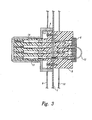
- Figure 3 illustrates one example of a replaced connection.
- a short length of insulated wire 12 installed on the rear insert 5 makes a connection between a contact 13 isolated from the board and another contact 14.
Landscapes
- Engineering & Computer Science (AREA)
- Manufacturing & Machinery (AREA)
- Coupling Device And Connection With Printed Circuit (AREA)
- Multi-Conductor Connections (AREA)
Claims (7)
- Verbinderanordnung umfassend:(a) eine gedruckte Leiterplatte (1), welche eine erste Seite und eine zweite Seite und eine Mehrzahl von kupferplattierten Löchern darin aufweist;(b) eine Mehrzahl von einzeln entfernbaren länglichen Anschlussstiften, welche mit den Löchern in der gedruckten Leiterplatte mittels eines nachgiebigen Mittelabschnitts (2) in Eingriff und elektrisch verbunden sind, und welche an einem Ende derselben für einen Anschluss mit Einzeldrahtbuchsenanschlusseinrichtungen ausgestaltet sind;(c) einen Verbindereinsatz (7), welcher an der ersten Seite der gedruckten Leiterplatte positioniert ist und Löcher darin aufweist, welche sich von einer Seite des Einsatzes zur anderen erstrecken, und welcher dazu ausgestaltet ist, durch eine Seite desselben ein Ende der Stifte aufzunehmen, und an der anderen die Stifte mit einem Verbinder einer modularen Elektronikeinrichtung zu verbinden;(d) einen Rückeinsatz (5), welcher an der zweiten Seite der gedruckten Leiterplatte positioniert ist, und welcher Löcher darin aufweist, die dazu ausgestaltet sind, das andere Ende der Stifte durch eine Seite desselben aufzunehmen, und wobei ein MIL-I-81969 oder ein ähnliches Drahteinführwerkzeug von der anderen Seite einführbar ist.
- Verbinderanordnung nach Anspruch 1, wobei der Rückeinsatz aus einem isolierenden Material besteht und Halterungen entlang des Innenrands der Löcher aufweist, um die Buchsenanschlusseinrichtungen lösbar zu befestigen.
- Verbinderanordnung nach Anspruch 1 oder 2, welche zusätzlich einen Brückendraht (12) umfasst, der Buchsenanschlusseinrichtungen an beiden Enden desselben aufweist, und welcher eine elektrische Verbindung zwischen zwei Anschlussstiften an der Rückeinsatzseite der Anordnung bereitstellt.
- Verbinderanordnung nach Anspruch 1, 2 oder 3, welche zusätzlich einen länglichen Stift umfasst, der in einem der Löcher der Platte positioniert ist, wobei der Stift eine Isolierhülse (3) aufweist, welche verhindert, dass ein elektrisches Signal zwischen dem Stift und der Platte übertragen wird.
- Verbinderanordnung nach einem der Ansprüche 1-4,
wobei das Profil des Innenrands der Löcher im Verbindereinsatz und das Profil der Stifte ausgestaltet ist, um die Stifte an ihrer Stelle zu halten, wenn der Verbindereinsatz an seinem Platz befestigt ist. - Verbinderanordnung nach einem der Ansprüche 1-5, welche zusätzlich einen Bodeneinsatz (4) zwischen dem Verbindereinsatz und der gedruckten Leiterplatte umfasst, welcher verhindert, dass die Anschlüsse durch einen falsch ausgerichteten verbindenden Anschluss durch die gedruckte Leiterplatte gedrückt werden, und das Profil der Stifte und der Innenrand der Löcher im Bodeneinsatz sind ausgestaltet, um einen Anschlag für Stifte beim Einführen in die gedruckte Leiterplatte bereitzustellen.
- Verbinderanordnung nach einem der Ansprüche 1-6, welche zusätzlich ein Verbindergehäuse umfasst, das den Verbindereinsatz abdeckt.
Applications Claiming Priority (2)
| Application Number | Priority Date | Filing Date | Title |
|---|---|---|---|
| US159321 | 1980-06-13 | ||
| US09/159,321 US6231354B1 (en) | 1998-09-23 | 1998-09-23 | System for modifying printed wiring connections after installation |
Publications (3)
| Publication Number | Publication Date |
|---|---|
| EP0989631A2 EP0989631A2 (de) | 2000-03-29 |
| EP0989631A3 EP0989631A3 (de) | 2002-01-09 |
| EP0989631B1 true EP0989631B1 (de) | 2005-11-02 |
Family
ID=22572068
Family Applications (1)
| Application Number | Title | Priority Date | Filing Date |
|---|---|---|---|
| EP99202726A Expired - Lifetime EP0989631B1 (de) | 1998-09-23 | 1999-08-23 | Veränderungssystem für gedruckte Schaltungsverbindungen nach Installierung |
Country Status (5)
| Country | Link |
|---|---|
| US (1) | US6231354B1 (de) |
| EP (1) | EP0989631B1 (de) |
| CN (1) | CN1114970C (de) |
| CA (1) | CA2280322C (de) |
| DE (1) | DE69928058T2 (de) |
Families Citing this family (6)
| Publication number | Priority date | Publication date | Assignee | Title |
|---|---|---|---|---|
| EP1238849B1 (de) * | 2001-03-07 | 2013-05-15 | Continental Automotive GmbH | Instrumententafel für ein Kraftfahrzeug |
| US7121875B2 (en) * | 2003-12-09 | 2006-10-17 | The Boeing Company | Integration area, system and method for providing interconnections among components |
| US7074073B2 (en) * | 2004-01-15 | 2006-07-11 | The Boeing Company | Electrical connector insert and apparatus and associated fabrication method |
| TWM257568U (en) * | 2004-02-18 | 2005-02-21 | Acbel Polytech Inc | A switching device for the single-phase/three-phase power supply |
| US7351115B1 (en) | 2007-01-17 | 2008-04-01 | International Business Machines Corporation | Method for modifying an electrical connector |
| JP2013114830A (ja) * | 2011-11-28 | 2013-06-10 | Tyco Electronics Japan Kk | 防水型コネクタ、防水型コネクタの実装構造及び実装方法 |
Citations (1)
| Publication number | Priority date | Publication date | Assignee | Title |
|---|---|---|---|---|
| US4173387A (en) * | 1978-03-28 | 1979-11-06 | Amp Incorporated | Snap-on pin header |
Family Cites Families (13)
| Publication number | Priority date | Publication date | Assignee | Title |
|---|---|---|---|---|
| US3601750A (en) * | 1970-02-09 | 1971-08-24 | Berg Electronics Inc | Circuit board connector |
| US4017143A (en) * | 1975-12-16 | 1977-04-12 | Litton Systems, Inc. | Solderless electrical contact |
| US4418972A (en) | 1982-02-01 | 1983-12-06 | Burroughs Corporation | Electrical connector for printed wiring board |
| US4619495A (en) * | 1982-09-07 | 1986-10-28 | Sochor Jerzy R | High-density press-fit cardedge connectors |
| US4530551A (en) | 1984-01-12 | 1985-07-23 | Burroughs Corp. | Circuit change pin for printed wiring board |
| FR2582867B1 (fr) * | 1985-06-03 | 1990-01-19 | Souriau | Installation de repartition et de connexion electrique a grand nombre de conducteurs, notamment pour l'aeronautique |
| US4909751A (en) | 1988-09-20 | 1990-03-20 | The United States Of America As Represented By The Secretary Of The Navy | Underwater mateable electrical connector |
| US4874326A (en) | 1988-09-20 | 1989-10-17 | The United States Of America As Represented By The Secretary Of The Navy | Elastomeric electrical isolation membrane |
| US5127838A (en) | 1990-02-23 | 1992-07-07 | General Electric Company | Plated electrical connectors |
| EP0608220B1 (de) | 1991-10-17 | 1996-02-28 | Itt Industries, Inc. | Verbinder mit auswechselbaren kontakten |
| JP2910390B2 (ja) | 1992-03-31 | 1999-06-23 | 日本電気株式会社 | コネクタ |
| US5312265A (en) | 1992-08-10 | 1994-05-17 | Dow Corning Corporation | Electrical connector suitable for use with variable numbers of electrical conductors |
| DE4341103C1 (de) | 1993-12-02 | 1995-01-12 | Harting Elektronik Gmbh | Elektrischer Steckverbinder |
-
1998
- 1998-09-23 US US09/159,321 patent/US6231354B1/en not_active Expired - Lifetime
-
1999
- 1999-08-13 CA CA002280322A patent/CA2280322C/en not_active Expired - Lifetime
- 1999-08-23 DE DE69928058T patent/DE69928058T2/de not_active Expired - Lifetime
- 1999-08-23 EP EP99202726A patent/EP0989631B1/de not_active Expired - Lifetime
- 1999-09-21 CN CN99120345A patent/CN1114970C/zh not_active Expired - Lifetime
Patent Citations (1)
| Publication number | Priority date | Publication date | Assignee | Title |
|---|---|---|---|---|
| US4173387A (en) * | 1978-03-28 | 1979-11-06 | Amp Incorporated | Snap-on pin header |
Also Published As
| Publication number | Publication date |
|---|---|
| CN1114970C (zh) | 2003-07-16 |
| CA2280322C (en) | 2002-07-02 |
| DE69928058D1 (de) | 2005-12-08 |
| CN1248802A (zh) | 2000-03-29 |
| US6231354B1 (en) | 2001-05-15 |
| EP0989631A2 (de) | 2000-03-29 |
| EP0989631A3 (de) | 2002-01-09 |
| DE69928058T2 (de) | 2006-07-13 |
| CA2280322A1 (en) | 2000-03-23 |
Similar Documents
| Publication | Publication Date | Title |
|---|---|---|
| US4179172A (en) | Modular hardware packaging apparatus | |
| US4548453A (en) | Right angle coaxial plug connector | |
| US4597631A (en) | Printed circuit card hybrid | |
| US4418972A (en) | Electrical connector for printed wiring board | |
| US3551874A (en) | Multiple coaxial connector | |
| US4782245A (en) | Connecting and switching apparatus with selectable connections | |
| US4702707A (en) | Power contact having removable mating components | |
| US4053199A (en) | Cable connectable bulkhead filter array | |
| US5010446A (en) | Multi-edge extender board | |
| EP0308092A2 (de) | Abgeschirmtes Kabelende für einen elektrischen Steckverbinder | |
| US6390829B1 (en) | Electrical connector assembly for a printed circuit board | |
| EP0260967B1 (de) | Steckverbinder mit verformbarem Haltebügel | |
| EP0152743A1 (de) | Modularer elekrischer Steckverbinder | |
| EP0989631B1 (de) | Veränderungssystem für gedruckte Schaltungsverbindungen nach Installierung | |
| EP0522798A3 (de) | Elektrischer Verbinder | |
| US6086388A (en) | Auxiliary switch system for use with removable circuit breaker | |
| EP3776749B1 (de) | In längsrichtung ausdehnbarer elektrischer verbinder | |
| US3649956A (en) | Replaceable electrical connector | |
| CA1163376A (en) | Modular connector assembly having an electrical contact | |
| EP0643448A1 (de) | Koaxialverbinder zur Verbindung mit Leiterplatten | |
| US4695923A (en) | Printed circuit board bolt-on power distribution system | |
| JPH09214154A (ja) | 自動挿入および抜去方式電子回路基板用ラック、ならびにラックおよびそのキャビネット、および電子回路基板の取り外し方法 | |
| US20010016456A1 (en) | Cable connector for a shielded cable | |
| WO1999030389A1 (en) | Connector | |
| US5813867A (en) | RF connector with quick disconnect |
Legal Events
| Date | Code | Title | Description |
|---|---|---|---|
| PUAI | Public reference made under article 153(3) epc to a published international application that has entered the european phase |
Free format text: ORIGINAL CODE: 0009012 |
|
| AK | Designated contracting states |
Kind code of ref document: A2 Designated state(s): AT BE CH CY DE DK ES FI FR GB GR IE IT LI LU MC NL PT SE Kind code of ref document: A2 Designated state(s): DE FR GB |
|
| AX | Request for extension of the european patent |
Free format text: AL;LT;LV;MK;RO;SI |
|
| PUAL | Search report despatched |
Free format text: ORIGINAL CODE: 0009013 |
|
| AK | Designated contracting states |
Kind code of ref document: A3 Designated state(s): AT BE CH CY DE DK ES FI FR GB GR IE IT LI LU MC NL PT SE |
|
| AX | Request for extension of the european patent |
Free format text: AL;LT;LV;MK;RO;SI |
|
| RIC1 | Information provided on ipc code assigned before grant |
Free format text: 7H 01R 29/00 A |
|
| 17P | Request for examination filed |
Effective date: 20020124 |
|
| AKX | Designation fees paid |
Free format text: DE FR GB |
|
| 17Q | First examination report despatched |
Effective date: 20030602 |
|
| GRAP | Despatch of communication of intention to grant a patent |
Free format text: ORIGINAL CODE: EPIDOSNIGR1 |
|
| GRAS | Grant fee paid |
Free format text: ORIGINAL CODE: EPIDOSNIGR3 |
|
| GRAA | (expected) grant |
Free format text: ORIGINAL CODE: 0009210 |
|
| AK | Designated contracting states |
Kind code of ref document: B1 Designated state(s): DE FR GB |
|
| REG | Reference to a national code |
Ref country code: GB Ref legal event code: FG4D |
|
| REF | Corresponds to: |
Ref document number: 69928058 Country of ref document: DE Date of ref document: 20051208 Kind code of ref document: P |
|
| ET | Fr: translation filed | ||
| PLBE | No opposition filed within time limit |
Free format text: ORIGINAL CODE: 0009261 |
|
| STAA | Information on the status of an ep patent application or granted ep patent |
Free format text: STATUS: NO OPPOSITION FILED WITHIN TIME LIMIT |
|
| 26N | No opposition filed |
Effective date: 20060803 |
|
| REG | Reference to a national code |
Ref country code: FR Ref legal event code: PLFP Year of fee payment: 18 |
|
| REG | Reference to a national code |
Ref country code: FR Ref legal event code: PLFP Year of fee payment: 19 |
|
| REG | Reference to a national code |
Ref country code: FR Ref legal event code: PLFP Year of fee payment: 20 |
|
| PGFP | Annual fee paid to national office [announced via postgrant information from national office to epo] |
Ref country code: DE Payment date: 20180829 Year of fee payment: 20 Ref country code: FR Payment date: 20180827 Year of fee payment: 20 |
|
| PGFP | Annual fee paid to national office [announced via postgrant information from national office to epo] |
Ref country code: GB Payment date: 20180828 Year of fee payment: 20 |
|
| REG | Reference to a national code |
Ref country code: DE Ref legal event code: R071 Ref document number: 69928058 Country of ref document: DE |
|
| REG | Reference to a national code |
Ref country code: GB Ref legal event code: PE20 Expiry date: 20190822 |
|
| PG25 | Lapsed in a contracting state [announced via postgrant information from national office to epo] |
Ref country code: GB Free format text: LAPSE BECAUSE OF EXPIRATION OF PROTECTION Effective date: 20190822 |