EP0989594A2 - Process chamber - Google Patents
Process chamber Download PDFInfo
- Publication number
- EP0989594A2 EP0989594A2 EP99810788A EP99810788A EP0989594A2 EP 0989594 A2 EP0989594 A2 EP 0989594A2 EP 99810788 A EP99810788 A EP 99810788A EP 99810788 A EP99810788 A EP 99810788A EP 0989594 A2 EP0989594 A2 EP 0989594A2
- Authority
- EP
- European Patent Office
- Prior art keywords
- process chamber
- rotary head
- turret
- wafer
- chamber according
- Prior art date
- Legal status (The legal status is an assumption and is not a legal conclusion. Google has not performed a legal analysis and makes no representation as to the accuracy of the status listed.)
- Granted
Links
Images


Classifications
-
- H—ELECTRICITY
- H01—ELECTRIC ELEMENTS
- H01L—SEMICONDUCTOR DEVICES NOT COVERED BY CLASS H10
- H01L21/00—Processes or apparatus adapted for the manufacture or treatment of semiconductor or solid state devices or of parts thereof
- H01L21/67—Apparatus specially adapted for handling semiconductor or electric solid state devices during manufacture or treatment thereof; Apparatus specially adapted for handling wafers during manufacture or treatment of semiconductor or electric solid state devices or components ; Apparatus not specifically provided for elsewhere
- H01L21/683—Apparatus specially adapted for handling semiconductor or electric solid state devices during manufacture or treatment thereof; Apparatus specially adapted for handling wafers during manufacture or treatment of semiconductor or electric solid state devices or components ; Apparatus not specifically provided for elsewhere for supporting or gripping
- H01L21/687—Apparatus specially adapted for handling semiconductor or electric solid state devices during manufacture or treatment thereof; Apparatus specially adapted for handling wafers during manufacture or treatment of semiconductor or electric solid state devices or components ; Apparatus not specifically provided for elsewhere for supporting or gripping using mechanical means, e.g. chucks, clamps or pinches
- H01L21/68714—Apparatus specially adapted for handling semiconductor or electric solid state devices during manufacture or treatment thereof; Apparatus specially adapted for handling wafers during manufacture or treatment of semiconductor or electric solid state devices or components ; Apparatus not specifically provided for elsewhere for supporting or gripping using mechanical means, e.g. chucks, clamps or pinches the wafers being placed on a susceptor, stage or support
- H01L21/68721—Apparatus specially adapted for handling semiconductor or electric solid state devices during manufacture or treatment thereof; Apparatus specially adapted for handling wafers during manufacture or treatment of semiconductor or electric solid state devices or components ; Apparatus not specifically provided for elsewhere for supporting or gripping using mechanical means, e.g. chucks, clamps or pinches the wafers being placed on a susceptor, stage or support characterised by edge clamping, e.g. clamping ring
-
- H—ELECTRICITY
- H01—ELECTRIC ELEMENTS
- H01L—SEMICONDUCTOR DEVICES NOT COVERED BY CLASS H10
- H01L21/00—Processes or apparatus adapted for the manufacture or treatment of semiconductor or solid state devices or of parts thereof
- H01L21/67—Apparatus specially adapted for handling semiconductor or electric solid state devices during manufacture or treatment thereof; Apparatus specially adapted for handling wafers during manufacture or treatment of semiconductor or electric solid state devices or components ; Apparatus not specifically provided for elsewhere
- H01L21/67005—Apparatus not specifically provided for elsewhere
- H01L21/67011—Apparatus for manufacture or treatment
- H01L21/6715—Apparatus for applying a liquid, a resin, an ink or the like
-
- H—ELECTRICITY
- H01—ELECTRIC ELEMENTS
- H01L—SEMICONDUCTOR DEVICES NOT COVERED BY CLASS H10
- H01L21/00—Processes or apparatus adapted for the manufacture or treatment of semiconductor or solid state devices or of parts thereof
- H01L21/67—Apparatus specially adapted for handling semiconductor or electric solid state devices during manufacture or treatment thereof; Apparatus specially adapted for handling wafers during manufacture or treatment of semiconductor or electric solid state devices or components ; Apparatus not specifically provided for elsewhere
- H01L21/683—Apparatus specially adapted for handling semiconductor or electric solid state devices during manufacture or treatment thereof; Apparatus specially adapted for handling wafers during manufacture or treatment of semiconductor or electric solid state devices or components ; Apparatus not specifically provided for elsewhere for supporting or gripping
- H01L21/687—Apparatus specially adapted for handling semiconductor or electric solid state devices during manufacture or treatment thereof; Apparatus specially adapted for handling wafers during manufacture or treatment of semiconductor or electric solid state devices or components ; Apparatus not specifically provided for elsewhere for supporting or gripping using mechanical means, e.g. chucks, clamps or pinches
- H01L21/68714—Apparatus specially adapted for handling semiconductor or electric solid state devices during manufacture or treatment thereof; Apparatus specially adapted for handling wafers during manufacture or treatment of semiconductor or electric solid state devices or components ; Apparatus not specifically provided for elsewhere for supporting or gripping using mechanical means, e.g. chucks, clamps or pinches the wafers being placed on a susceptor, stage or support
- H01L21/68735—Apparatus specially adapted for handling semiconductor or electric solid state devices during manufacture or treatment thereof; Apparatus specially adapted for handling wafers during manufacture or treatment of semiconductor or electric solid state devices or components ; Apparatus not specifically provided for elsewhere for supporting or gripping using mechanical means, e.g. chucks, clamps or pinches the wafers being placed on a susceptor, stage or support characterised by edge profile or support profile
-
- H—ELECTRICITY
- H01—ELECTRIC ELEMENTS
- H01L—SEMICONDUCTOR DEVICES NOT COVERED BY CLASS H10
- H01L21/00—Processes or apparatus adapted for the manufacture or treatment of semiconductor or solid state devices or of parts thereof
- H01L21/67—Apparatus specially adapted for handling semiconductor or electric solid state devices during manufacture or treatment thereof; Apparatus specially adapted for handling wafers during manufacture or treatment of semiconductor or electric solid state devices or components ; Apparatus not specifically provided for elsewhere
- H01L21/683—Apparatus specially adapted for handling semiconductor or electric solid state devices during manufacture or treatment thereof; Apparatus specially adapted for handling wafers during manufacture or treatment of semiconductor or electric solid state devices or components ; Apparatus not specifically provided for elsewhere for supporting or gripping
- H01L21/687—Apparatus specially adapted for handling semiconductor or electric solid state devices during manufacture or treatment thereof; Apparatus specially adapted for handling wafers during manufacture or treatment of semiconductor or electric solid state devices or components ; Apparatus not specifically provided for elsewhere for supporting or gripping using mechanical means, e.g. chucks, clamps or pinches
- H01L21/68714—Apparatus specially adapted for handling semiconductor or electric solid state devices during manufacture or treatment thereof; Apparatus specially adapted for handling wafers during manufacture or treatment of semiconductor or electric solid state devices or components ; Apparatus not specifically provided for elsewhere for supporting or gripping using mechanical means, e.g. chucks, clamps or pinches the wafers being placed on a susceptor, stage or support
- H01L21/68785—Apparatus specially adapted for handling semiconductor or electric solid state devices during manufacture or treatment thereof; Apparatus specially adapted for handling wafers during manufacture or treatment of semiconductor or electric solid state devices or components ; Apparatus not specifically provided for elsewhere for supporting or gripping using mechanical means, e.g. chucks, clamps or pinches the wafers being placed on a susceptor, stage or support characterised by the mechanical construction of the susceptor, stage or support
-
- H—ELECTRICITY
- H01—ELECTRIC ELEMENTS
- H01L—SEMICONDUCTOR DEVICES NOT COVERED BY CLASS H10
- H01L21/00—Processes or apparatus adapted for the manufacture or treatment of semiconductor or solid state devices or of parts thereof
- H01L21/67—Apparatus specially adapted for handling semiconductor or electric solid state devices during manufacture or treatment thereof; Apparatus specially adapted for handling wafers during manufacture or treatment of semiconductor or electric solid state devices or components ; Apparatus not specifically provided for elsewhere
- H01L21/683—Apparatus specially adapted for handling semiconductor or electric solid state devices during manufacture or treatment thereof; Apparatus specially adapted for handling wafers during manufacture or treatment of semiconductor or electric solid state devices or components ; Apparatus not specifically provided for elsewhere for supporting or gripping
- H01L21/687—Apparatus specially adapted for handling semiconductor or electric solid state devices during manufacture or treatment thereof; Apparatus specially adapted for handling wafers during manufacture or treatment of semiconductor or electric solid state devices or components ; Apparatus not specifically provided for elsewhere for supporting or gripping using mechanical means, e.g. chucks, clamps or pinches
- H01L21/68714—Apparatus specially adapted for handling semiconductor or electric solid state devices during manufacture or treatment thereof; Apparatus specially adapted for handling wafers during manufacture or treatment of semiconductor or electric solid state devices or components ; Apparatus not specifically provided for elsewhere for supporting or gripping using mechanical means, e.g. chucks, clamps or pinches the wafers being placed on a susceptor, stage or support
- H01L21/68792—Apparatus specially adapted for handling semiconductor or electric solid state devices during manufacture or treatment thereof; Apparatus specially adapted for handling wafers during manufacture or treatment of semiconductor or electric solid state devices or components ; Apparatus not specifically provided for elsewhere for supporting or gripping using mechanical means, e.g. chucks, clamps or pinches the wafers being placed on a susceptor, stage or support characterised by the construction of the shaft
Definitions
- the invention relates to a process chamber in which various Processing steps in semiconductor production can be carried out, according to the preamble of the independent claim.
- Processing steps are particularly media such as liquids (e.g. Etching liquids, cleaning liquids, photoresists, developers, etc.), Vapors (e.g. metal vapors or liquid vapors, etc.), gases (etching gases, Oxygen for oxidation, purge gases, protective gases, etc.), suspensions (e.g.
- liquids e.g. Etching liquids, cleaning liquids, photoresists, developers, etc.
- Vapors e.g. metal vapors or liquid vapors, etc.
- gases etching gases, Oxygen for oxidation, purge gases, protective gases, etc.
- suspensions e.g.
- photoresist from a liquid nozzle can be applied to the rotating wafer as it is for example, described in US-A-5,395,803.
- photoresist can be applied to the resting wafer and this then rotate, such as in US-A-4,822,639 is described.
- the wafers are known by means of Processes such as CVD (Chemical Vapor Deposition) or PVD (Physical Vapor Deposition) process.
- CVD Chemical Vapor Deposition
- PVD Physical Vapor Deposition
- Such methods are also suitable, for example, by Applying molten liquid silicon to a rotating one Plate to manufacture polycrystalline silicon wafers, similar to this at the Generation of the "thick" layers has already been described. This is for example, described in US-A-4,561,486.
- liquid or on a rotating wafer apply gaseous solvents to remove coatings, e.g. for removing photoresists. This is e.g. in US-A-4,749,440 or in US-A-4,510,176.
- caustic vapors or caustic gases become Etching of the wafers, as used, for example, in US Pat. No. 5,370,741, US-A-5,174,853 or US-A-5,248,380.
- the wafer, which is exposed to these vapors or gases is Etching process also rotates.
- it is also possible etch both sides of a wafer simultaneously US-A-4,857,142.
- plasma etching is done using an electric field ionized gas ("plasma") used for etching. This is for example in U.S. 4,230,515. In all of the etching processes described it is advantageous if the wafer is rotated.
- the wafer e.g. at a speed of about 500-1500 rpm rotated, bombarded with ion beams.
- the wafer e.g. at a speed of about 500-1500 rpm rotated, bombarded with ion beams.
- multiple wafers arranged from a turntable like this e.g. in US-A-4,745,287.
- spin-rinsing Similar to “spin-etching", the wafer with cleaning liquid, e.g. with ultrapure water. That too
- the wafers can be dried in this way: Centrifugal wafer dryer thrown outwards, see e.g. US-A-4,300,581.
- the wafer is usually rotated individually, or there are several Wafer together with the help of an appropriate rotatable Holding device rotates.
- This holding device is the following For the sake of simplicity referred to as the turret.
- the turret that holds the wafer stops and rotates, is often from below via a rotating shaft, sometimes driven from above.
- the rotating shaft via a seal from below or from above into the interior of the Process chamber introduced.
- the drive motor is usually located outside the interior of the process chamber to the interior of the Keep the process chamber free of contamination (clean room conditions) and to protect the engine from corrosion.
- the applicators are forcibly above or below of the turret. It is only in exceptional cases (application of gases) possible to treat the wafer from both sides. In any case, poses but the drive of the turret from below or from above one Restriction with regard to the arrangement of the applicators.
- This way of driving and storing the rotary head also provides one Restriction for the supply of the wafer or wafers.
- the wafer (the wafers) can - if the rotary head is driven from below - not be fed from below.
- Usually there is also a supply of Not possible above because of the arrangement of the applicators, so that in in such cases the wafer practically only from the side - more precisely can be fed from the side above the rotary head. This complicates significantly centering the wafer and also limits the freedom of the wafer Arrangement of the applicators because there is free access from the side to towards the center of the turret must be guaranteed.
- the feedability of the wafer should also be easier than with known process chambers.
- a process chamber as it is by the Features of the independent claim is characterized.
- a rotary head that can be driven in rotation in the process chamber arranged, which as a holder for a substantially disc-shaped processing object, e.g. for a wafer.
- at least one applicator provided for providing a medium that acts on the object to be processed.
- Radially around Means for storage and drive are arranged around the rotary head the turret. This radial arrangement allows, depending on Arrangement of the applicators, the wafer centrally from below or from above feed and thus facilitates centering of the wafer. Further is it radially by the arrangement of the means for storage and drive the rotating head possible, the inserted wafer both from above as well as from below, without this through a Drive shaft or the like is excluded.
- the means for mounting and driving the rotary head are preferably such trained to store and drive the rotary head without contact, in particular, these means comprise a magnetic one Bearing / drive unit, which is often referred to as a "bearingless motor”.
- the magnetic storage / drive unit can be an outside of the housing of the process chamber arranged stator and the Turret can be arranged within the housing, the (Non-magnetic) housing wall forms a can, which defines the interior of the housing seals against the outside.
- this allows the Gap between the turret and the stator can be kept small (which at same flooding results in greater stiffness of the bearing), on the other hand, a potentially corrosive medium always remains in the interior of the housing and cannot escape to the outside.
- the process chamber according to the invention can all six degrees of freedom of the turret, namely the two Degrees of freedom of displacement in the bearing plane, the axial Displacement, the two degrees of freedom of tilt and rotation, active be controllable. This enables a very precise positioning of the Turret with regard to each of the degrees of freedom, but is of course also from the electronics more complex than the two following Design variants.
- two degrees of freedom of the rotary head can be active be controllable, namely the two degrees of freedom of the shift in the Storage level, while the other four degrees of freedom are passively stabilized.
- the axial displacement and the tilt of the turret this means that one passively stabilized from its Position with respect to one of these three degrees of freedom Reluctance forces are returned to their stable position as long as the Deflection is not greater than a threshold. When crossing this threshold, however, is a stable bearing of the turret no longer exist.
- the rotation this means that the turret with e.g. can be magnetically coupled to the bearing stator and this Bearing stator itself is rotatable. Because of the magnetic Coupling is then rotated the turning head when turning the bearing stator.
- the rotary head can be actively controlled, namely the two degrees of freedom Shift in the bearing plane and the rotation while the other three Degrees of freedom, namely the axial displacement and the two Degrees of freedom of tilting, passively stabilized.
- the effort in the electronics is still comparatively low, on the other hand
- the stator does not need to be rotatable, but the rotating head can be driven in rotation by means of a rotating field.
- the turret is designed so that the one to be machined Object outside the interior of the process chamber with the rotary head can be connected that it is held by him. That too The object to be processed can then be moved into the Be brought inside the process chamber.
- This has the advantage that an exact positioning of the object, e.g. of the wafer, relative to that Turret can be done outside the interior of the process chamber where the turret is more accessible. It's also like that possible to turn the wafer very precisely with the rotary head only once connect, and then the unit formed from the turret and the wafer from one processing station to another processing station to pass on without having the wafer on another turret again must be positioned. This can be done within a system of using Process chambers connected to locks take place so that the Clean room conditions are not violated in the meantime, whereby the The degree of purity in successive process chambers always increases.
- the turret can be designed so that it from the turret held object - e.g. the wafer - from both sides from one from Applicator provided medium can be applied. This is advantageous in that, for example, both sides of the wafer simultaneously can be edited. The processing of the two sides can also be done sequentially. In any case, it is possible to use both sides of the wafer to process without the wafer having to be rotated like this The case is when - as with a large number of those discussed in the introduction Devices from the prior art - on a turntable with a Drive shaft rests.
- the turret can be essentially ring-shaped.
- the Inside the turret can also be a disc with through channels be fitted, whereby the object to be processed, e.g. the wafer, from Turret is held at a distance from this disc.
- That disc can form a nozzle system through which the wafer e.g. With Vapors or gases can be applied.
- the rotary head in the be essentially disc-shaped and the object to be held can be held in a central area of the turret. in the peripheral area around this central area is the turret sloping so that one on the object to be processed applied liquid, which when rotating the rotary head over the object to be processed flows outwards, over the peripheral one Area of the turret can run off.
- the rotary head has the peripheral, sloping area around a tub, which at the bottom there are openings for those caught in the tub Has liquid.
- This variant is advantageous in that the Air gap between the turret and the stator can be kept small can, on the other hand, the liquid is not already through this already small gap must run out. Instead, the liquid in the tub be caught and through the openings in the bottom of the Drain the tub.
- the as Holder for the object to be processed e.g. for the wafer, serving turret Means, with the help of a negative pressure to the object to be processed is directed, which sucks the object to be processed on the rotary head.
- This can preferably even outside the interior of the housing the process chamber so that the wafer is in an easily accessible place Positioned on the turret and can then be sucked. Once the turret is then sucked together with the sucked wafer into the Transported interior of the housing of the process chamber.
- a vacuum pump can be provided, which is preferably fed inductively becomes.
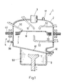
- FIG. 1 of an inventive Process chamber 1 comprises a housing 2, a rotary head 3 with magnetic active elements 30 (e.g. laminated soft iron), a storage / Drive stator 4 with a stator winding 40 and with magnetically active Elements 41 such as sheet metal soft iron parts and permanent magnets (not shown).
- the bearing / drive stator 4 is radially around the rotary head 3 arranged, which carries a wafer W.
- the applicators are preferably slidable and / or designed to be pivotable, which is indicated by corresponding arrows is indicated.
- stator winding 40 comprises a control winding for controlling the Position of the rotary head 3 in the storage level, i.e. in the storage / Drive stator 4, on the other hand, it comprises a drive winding for Driving the rotary head 3, the control winding and drive winding can form common winding
- the functionality and Various embodiments of such a bearingless motor are available known.
- the stator 4 Since the stator 4 is arranged outside the housing 2 of the process chamber is, there is an area of the housing 2 in the air gap between the Turret 3 and the stator 4 is arranged. To keep the air gap as small as possible
- a feed mechanism is also shown, which one Vacuum gripper 7 includes.
- This vacuum gripper 7 is in one in FIG Lock 8 arranged, which comprises two slides 80 and 81.
- the Slider 80 is movable in a plane perpendicular to the drawing plane, that is quasi out of the drawing level and into the drawing level, and opens the lock 8 to the outside. From the outside, the wafer W be applied to the vacuum gripper 7. Then the slider becomes 80 closed and the slide 81 opened.
- the vacuum gripper 7 can then transport the wafer W to the rotary head 3, the applicator, of course 53 must be withdrawn laterally in order to feed the wafer W not to hinder.
- the wafer W is already attached to the rotary head 3 outside the lock 8 or with this is connected, as will be explained in more detail.
- the rotary head 3 is then placed on the vacuum gripper 7 together with the wafer W. applied and then in the interior of the housing 2 Process chamber 1 transported.
- This has the advantage that, firstly, that Attach or connect the wafer W to the rotary head 3 in one place can take place (namely outside the lock), where the rotary head 3 is particularly accessible.
- Finally 1 shows an inlet connection 90 and an outlet connection 91 for supplying and discharging gases and an outlet pipe 92 for Draining liquids.
- Such a process chamber 1 is suitable is therefore also particularly suitable for the production of semiconductors simple structures such as thyristors (e.g. GTO's).
- Fig. 2 shows a further embodiment of an inventive Process chamber.
- the process chamber 1a here comprises the housing 2a, in the interior thereof the rotary head 3a is arranged, which carries the wafer W.
- the turret 3a is carried by the stator 4a and driven in rotation.
- the stator 4a is however, slidable in the axial direction and also to a small extent tiltable, as indicated by the corresponding arrows.
- a nozzle system 54a (applicator) is also provided in FIG. which, for example, a process gas in the interior of the housing 2a can initiate.
- This nozzle system 54a can be designed to be axially displaceable his.
- the process gas is discharged from the interior via the outlet connector 91a the process chamber 1a discharged again.
- a heating coil 55a (applicator), which below the rotary head 3a is arranged, and since the wafer W is freely accessible from below, can homogeneous heating of the wafer W can be achieved.
- other applicators such as electrodes or radiation sources or others Applicators arranged in the interior of the housing of the process chamber his.
- the process chamber 1a shown in FIG. 2 is particularly suitable for CVD (Chemical Vapor Deposition) processes.
- FIG. 3 is a section of an embodiment of a Process chamber 1b shown, in which the stator 4b in an indentation of the housing 2b is arranged. If the diameter of the rotary head 3b small compared to the diameter of the interior of the housing 2b to be held, e.g. around the wafer W together with the rotary head 3b is easier to remove from the interior of the housing 2b this embodiment very advantageous.
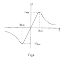
- the relationship between the restoring force F and the axial deflection z from the desired position of the rotary head is shown graphically. It can be seen that in the respective positive or negative axial direction (z-direction), the restoring force initially looks up to a maximum deflection z max or -z max, the amount of the restoring force increases up to a value F max or -F max , at Exceeding this deflection decreases again. This means that if, when the deflection z max or -z max is exceeded, the same force acts on the rotary head in the axial direction that led to the corresponding deflection, the rotary head escapes from the bearing.
- a rotary head 3c which in is essentially annular. This means that the wafer W can be edited from both sides.
- the rotary head 3c has means for sucking the wafer W in the form of a vacuum chamber 31c, in which a negative pressure can be generated via a valve 32c. Thereby the wafer is sucked against the O-rings 33c and 34c. This process can be done outside the interior of the housing. Subsequently the valve 32c is closed so that the negative pressure in the Vacuum chamber 31c is maintained and the wafer W to the O-rings 33c and 34c remains sucked.
- Fig. 6 shows an embodiment of a rotary head 3d, in the interior a disk 35d is arranged, which is provided with passage channels 36d is.
- This disc 35d acts as a nozzle system through which the Wafers W (here from below) are exposed to gases or vapors can.
- the wafer W is in one with the help of the spring-loaded grippers 37d Distance from the disc 35d (here above the disc 35d) kept.
- the Wafer W is therefore accessible from both sides, with the attachment of the wafer W on the rotating head 3d also outside the housing of the process chamber can be done.
- the rotary head 3d thus equipped with the wafer can then be in the interior of the housing of the process chamber can be introduced.
- FIG. 7 shows an embodiment of a process chamber 1e with a Housing 2e, in the interior of which a substantially disc-shaped Turret 3e is arranged.
- This rotary head 3e is with means for Firmly suck the wafer W, in a central area of the turret 3e.
- These means include a valve 32e (e.g. a ball valve). If negative pressure is now generated through the ball valve 32e, then in the vacuum chamber 31e generates a suction pressure under the wafer W, which sucks the wafer W against the O-ring 33e. Then you close the valve 32e, the wafer W remains sucked against the O-ring 33e. As mentioned earlier, this can be done outside the interior of the Housing 2e of the process chamber 1e take place.
- a valve 32e e.g. a ball valve
- a vacuum pump can be provided, which is inductive is fed, as already described with reference to FIG. 5, parts of the Energy of the drive rotating field can be used for supply.
- the turret drops outwards and ends in a tub 38e.
- This tub 38e is on its bottom Passage openings 39e provided. Now becomes one Liquid applicator 51e places a liquid F centrally on the wafer W.
- the liquid F flows due to the rotation of the rotary head 3e over the surface of the wafer W outwards over the wafer edge away, along the sloping areas of the rotary head 3e into the tub 38e and there is a backflow of liquid F which does not run off avoided, so that a homogeneous liquid film on the wafer W can arise.
- a corresponding Outlet connector (not shown) can be provided in the housing which the liquid F can be removed.
- the air gap can be chosen very small, which reduces the losses.
Abstract
Description
Die Erfindung betrifft eine Prozesskammer, in welcher verschiedene Bearbeitungsschritte bei der Halbleiterfertigung ausgeführt werden können, gemäss dem Oberbegriff des unabhängigen Patentanspruchs.The invention relates to a process chamber in which various Processing steps in semiconductor production can be carried out, according to the preamble of the independent claim.
Etliche Bearbeitungsschritte bei der Halbleiterfertigung, insbesondere bei der Herstellung von intergrierten Halbleiterschaltungen, erfolgen derart, dass der Wafer (eine Scheibe, auf welcher eine grosse Zahl solcher integrierter Halbleiterschaltungen angeordnet sind) in einer Prozesskammer rotiert wird. Dabei kommt oft noch hinzu, dass die einzelnen Schritte unter Reinraumbedingungen ausgeführt werden müssen. In den einzelnen Bearbeitungsschritten werden insbesondere Medien wie Flüssigkeiten (z.B. Ätzflüssigkeiten, Reinigungsflüssigkeiten, Fotolacke, Entwickler, etc.), Dämpfe (z.B. Metalldämpfe oder Flüssigkeitsdämpfe, etc.), Gase (Ätzgase, Sauerstoff zur Oxidation, Spülgase, Schutzgase, etc.), Suspensionen (z.B. zur Herstellung von Passivierungsschichten und anderen Dickfilmschichten), geschmolzenes Polysilizium, elektromagnetische Wellen, Ionenstrahlen und andere mehr auf den Wafer appliziert bzw. wirken auf den Wafer ein. Beispielhaft sollen nachfolgend einige ausgewählte Bearbeitungsschritte kurz genannt werden, welche in einer Prozesskammer erfolgen, in welcher der Wafer rotiert wird. Several processing steps in semiconductor manufacturing, especially in the Manufacture of integrated semiconductor circuits take place in such a way that the Wafer (a disc on which a large number of such integrated Semiconductor circuits are arranged) is rotated in a process chamber. Often there is also the fact that the individual steps are below Clean room conditions must be carried out. In each of Processing steps are particularly media such as liquids (e.g. Etching liquids, cleaning liquids, photoresists, developers, etc.), Vapors (e.g. metal vapors or liquid vapors, etc.), gases (etching gases, Oxygen for oxidation, purge gases, protective gases, etc.), suspensions (e.g. for the production of passivation layers and other thick film layers), molten polysilicon, electromagnetic waves, ion beams and others applied more to the wafer or act on the wafer. Some selected processing steps are briefly shown below as examples are mentioned, which take place in a process chamber in which the Wafer is rotated.
Beispielsweise kann Fotolack aus einer Flüssigkeitsdüse (oder auch einer Spray-Düse) auf den rotierenden Wafer appliziert werden, wie es beispielsweise in der US-A-5,395,803 beschrieben ist. Alternativ ist es auch möglich, den Fotolack auf den ruhenden Wafer aufzutragen und diesen anschliessend zu rotieren, wie dies beispielsweise in der US-A-4,822,639 beschrieben ist.For example, photoresist from a liquid nozzle (or one Spray nozzle) can be applied to the rotating wafer as it is for example, described in US-A-5,395,803. Alternatively it is possible to apply the photoresist to the resting wafer and this then rotate, such as in US-A-4,822,639 is described.
Aufgrund der erhöhten Obeflächenspannung am Rand des Wafers kommt es hier oft zu leichten Überhöhungen, die unerwünscht sind und entfernt werden müssen. Dies erfolgt, indem auf den rotierenden Wafer im peripheren Bereich ein Lösungsmittel appliziert wird, wie es z.B. in der US-A-4,510,176 beschrieben ist. Dieser Bearbeitungsschritt kann beispielsweise auch zusammen mit dem Auftragen des Fotolacks kombiniert werden, was beispielsweise in der US-A-5,773,083 beschrieben ist.Because of the increased surface tension at the edge of the wafer, it happens here often too slight increases, which are undesirable and are removed have to. This is done by turning on the rotating wafer in the peripheral Area a solvent is applied, e.g. in US-A-4,510,176 is described. This processing step can also, for example combined with the application of the photoresist what for example, described in US-A-5,773,083.
Bei einem anderen Bearbeitungsschritt werden beispielsweise Suspensionen appliziert und dadurch Passivierungsschichten auf dem Wafer erzeugt. Dabei werden ähnlich wie bei der Fotolackbeschichtung beispielsweise Flüssigkeiten mit kleinsten Glas- oder Siliziumdioxidteilchen aufgetragen, die dann die Passivierungsschicht erzeugen. Derartige Bearbeitungsschritte sind beispielsweise in der US-A-5,376,176 oder in der US-A-5,328,871 beschrieben. Bei auf diese Weise hergestellten Schichten ist ebenfalls ein Bearbeitungsschritt erforderlich, in welchem Kantenüberhöhungen entfernt werden (wie z.B. in der US-A-4,732,785 beschrieben).In another processing step, for example, suspensions applied and thereby passivation layers generated on the wafer. Here are similar to photoresist coating, for example Liquids with tiny glass or silicon dioxide particles applied, the then create the passivation layer. Such processing steps are for example in US-A-5,376,176 or in US-A-5,328,871 described. In the case of layers produced in this way, there is also a Machining step required in which edge peaks are removed (such as described in U.S.-A-4,732,785).
Ferner ist es auch möglich, auf rotierenden Wafern Dünnfilmschichten zu erzeugen, z.B. aus Siliziumdioxid, aus Metallen, oder aus Kohlenstoff (DLC = Diamond Like Carbon). Zu diesem Zweck werden die Wafer mittels bekannter Verfahren wie beispielsweise CVD-Verfahren (Chemical Vapour Deposition) oder PVD-Verfahren (Physical Vapour Deposition) beschichtet. Bei diesen Verfahren kann durch die Rotation des Wafers die Homogenität der Beschichtung des Wafers vorteilhaft beeinflusst werden, insbesondere dann, wenn der Wafer sehr schnell rotiert, z.B. mit Drehzahlen bis zu 16.000 rpm. Derartige Verfahren sind beispielsweise in der US-A-5,630,881 beschrieben.Furthermore, it is also possible to add thin film layers to rotating wafers generate, e.g. from silicon dioxide, from metals, or from carbon (DLC = Diamond Like Carbon). For this purpose, the wafers are known by means of Processes such as CVD (Chemical Vapor Deposition) or PVD (Physical Vapor Deposition) process. With these The rotation of the wafer can improve the homogeneity of the process Coating of the wafer can be influenced advantageously, especially if if the wafer rotates very quickly, e.g. with speeds up to 16,000 rpm. Such methods are described for example in US-A-5,630,881.
Ferner sind derartige Verfahren auch dazu geeignet, beispielsweise durch Auftragen von geschmolzenem flüssigem Silizium auf einen rotierenden Teller polykristalline Silizium-Wafer zu herzustellen, ähnlich wie dies bei der Erzeugung der "dicken" Schichten bereits beschrieben worden ist. Dies ist beispielsweise in der US-A-4,561,486 beschrieben.Such methods are also suitable, for example, by Applying molten liquid silicon to a rotating one Plate to manufacture polycrystalline silicon wafers, similar to this at the Generation of the "thick" layers has already been described. This is for example, described in US-A-4,561,486.
Weiterhin ist es auch möglich, auf einen rotierenden Wafer flüssige oder gasförmige Lösungsmittel zum Entfernen von Beschichtungen zu applizieren, z.B. zum Entfernen von Fotolacken. Dies ist z.B. in der US-A-4,749,440 oder in der US-A-4,510,176 beschrieben.Furthermore, it is also possible to liquid or on a rotating wafer apply gaseous solvents to remove coatings, e.g. for removing photoresists. This is e.g. in US-A-4,749,440 or in US-A-4,510,176.
Darüberhinaus ist es auch möglich, den rotierenden Wafer für verschiedene Ätzprozesse auszunutzen. Dies ist insofern von Vorteil, als dabei eine homogene Ätzgeschwindigkeit üder den ganzen Wafer erreicht wird, was insbesondere von Wichtigkeit sein kann um ein Unterätzen zu vermeiden. Wird beispielsweise aus einer Düse Ätzflüssigkeit auf den rotierenden Wafer appliziert, so bildet sich ein homogener Ätzfilm aus, welcher gesteuert durch die Flüssigkeitszufuhr gleichmässig erneuert wird. Dies ist beispielsweise in der US-A-4,903,717 oder der US-A- 4,350,562 beschrieben. Alternativ ist es auch möglich, den Wafer auf einem Flüssigkeitsfilm rotieren zu lassen, wie dies in der US-A-4,350,562 beschrieben ist.In addition, it is also possible to use the rotating wafer for different To use etching processes. This is advantageous in that one is homogeneous etching speed is achieved over the entire wafer, which can be particularly important to avoid undercutting. For example, etching liquid from a nozzle onto the rotating wafer applied, a homogeneous etching film forms, which is controlled by the fluid supply is renewed evenly. This is for example in US-A-4,903,717 or US-A-4,350,562. Alternatively it is also possible to rotate the wafer on a liquid film, such as this is described in US-A-4,350,562.
Bei anderen Atzprozessen werden ätzende Dämpfe oder ätzende Gase zum Ätzen der Wafer eingesetzt, wie dies beispielsweise in der US-A-5,370,741, der US-A-5,174,853 oder der US-A-5,248,380 beschrieben ist. Der Wafer, welcher diesen Dämpfen oder Gasen ausgesetzt ist, wird während des Ätzprozesses ebenfalls rotiert. Bei diesem Ätzprozess ist es auch möglich, gleichzeitig beide Seiten eines Wafers zu ätzen (US-A-4,857,142). Beim sogenannten "Plasma-Ätzen" wird ein mit Hilfe eines elektrischen Felds ionisiertes Gas ("Plasma") zum Ätzen eingesetzt. Dies ist beispielsweise in der US-A-4,230,515 beschrieben. Bei all den beschriebenen Ätzprozessen ist es von Vorteil, wenn der Wafer rotiert wird.In other etching processes, caustic vapors or caustic gases become Etching of the wafers, as used, for example, in US Pat. No. 5,370,741, US-A-5,174,853 or US-A-5,248,380. The wafer, which is exposed to these vapors or gases is Etching process also rotates. With this etching process, it is also possible etch both sides of a wafer simultaneously (US-A-4,857,142). At the So-called "plasma etching" is done using an electric field ionized gas ("plasma") used for etching. This is for example in U.S. 4,230,515. In all of the etching processes described it is advantageous if the wafer is rotated.
Ferner ist es auch möglich, lonenimplantationen auf rotierenden Wafern durchzuführen. Hierbei wird der Wafer, der z.B. mit einer Drehzahl von etwa 500-1500 rpm rotiert, mit Ionenstrahlen beschossen. Hierzu sind normalerweise mehrere Wafer aus einem Drehteller angeordnet, wie dies z.B. in der US-A-4,745,287 beschrieben ist.Furthermore, it is also possible to perform ion implantations on rotating wafers perform. Here, the wafer, e.g. at a speed of about 500-1500 rpm rotated, bombarded with ion beams. For this are usually multiple wafers arranged from a turntable like this e.g. in US-A-4,745,287.
Weitere Bearbeitungsschritte mit rotierenden Wafern betreffen das Waschen der Wafer ("spin-rinsing") ähnlich wie beim "spin-etching", wobei der Wafer mit Reinigungsflüssigkeit beaufschlagt wird, z.B. mit Reinstwasser. Auch das Trocknen der Wafer ist so möglich: Flüssigkeitsreste werden durch Zentrifugalkräfte ("centrifugal wafer dryer") nach aussen geschleudert, siehe z.B. US-A-4,300,581.Further processing steps with rotating wafers concern washing the wafer ("spin-rinsing") similar to "spin-etching", the wafer with cleaning liquid, e.g. with ultrapure water. That too The wafers can be dried in this way: Centrifugal wafer dryer thrown outwards, see e.g. US-A-4,300,581.
Obgleich vorstehend nur eine ausgewälte Anzahl von Prozessen bzw. Prozessschritten beschrieben sind, gibt es noch zahlreiche weitere solcher Prozessschritte oder Bearbeitungsschritte, die in einer Prozesskammer mit rotierendem Wafer durchgeführt werden. Dabei werden in der Regel mit Hilfe von Applikatoren wie Düsen und Düsensysteme (Köpfe mit einer Vielzahl von Düsen), Rohrsystemen, Strahlenquellen, Elektroden, Heizelementen und Heizstrahlern, verschiedene Medien - darunter soll auch Strahlung verstanden werden - wie Flüssigkeiten, Suspensionen mit Feststoffen, Gase und Dämpfe, elektrogmagnetische Felder, Ionenstrahlen etc. auf den Wafer appliziert.Although only a selected number of processes or Process steps are described, there are numerous other such Process steps or processing steps in a process chamber with rotating wafer. This is usually done with the help of applicators such as nozzles and nozzle systems (heads with a variety of Nozzles), pipe systems, radiation sources, electrodes, heating elements and Radiant heaters, various media - including radiation are understood - such as liquids, suspensions with solids, gases and vapors, electro-magnetic fields, ion beams, etc. on the wafer applied.
Der Wafer wird dabei zumeist einzeln rotiert, oder aber es werden mehrere Wafer gemeinsam mit Hilfe einer enstprechenden rotierbaren Haltevorrichtung rotiert. Diese Haltevorrichtung wird im folgenden der Einfachheit halber als Drehkopf bezeichnet. Der Drehkopf, der den Wafer hält und rotiert, wird oft über eine rotierende Welle zumeist von unten her, manchmal auch von oben her, angetrieben. Dabei wird die rotierende Welle über eine Dichtung von unten her oder von oben her in den Innenraum der Prozesskammer eingeführt. Der Antriebsmotor befindet sich in der Regel ausserhalb des Innenraums der Prozesskammer, um den Innenraum der Prozesskammer von Verunreinigungen freizuhalten (Reinraumbedingungen) und um den Motor vor Korrosion zu schützen.The wafer is usually rotated individually, or there are several Wafer together with the help of an appropriate rotatable Holding device rotates. This holding device is the following For the sake of simplicity referred to as the turret. The turret that holds the wafer stops and rotates, is often from below via a rotating shaft, sometimes driven from above. The rotating shaft via a seal from below or from above into the interior of the Process chamber introduced. The drive motor is usually located outside the interior of the process chamber to the interior of the Keep the process chamber free of contamination (clean room conditions) and to protect the engine from corrosion.
Die Applikatoren (Düsen, Düsensysteme, Rohrleitungen, Elektroden, Strahlungsquellen, etc.) befinden sich zwangsweise oberhalb oder unterhalb des Drehkopfs. Nur in Ausnahmefällen (Applikation von Gasen) ist es möglich, den Wafer von beiden Seiten her zu behandeln. In jedem Fall stellt aber der Antrieb des Drehkopfs von unten her oder von oben her eine Einschränkung im Hinblick auf die Anordnung der Applikatoren dar.The applicators (nozzles, nozzle systems, pipes, electrodes, Radiation sources, etc.) are forcibly above or below of the turret. It is only in exceptional cases (application of gases) possible to treat the wafer from both sides. In any case, poses but the drive of the turret from below or from above one Restriction with regard to the arrangement of the applicators.
Diese Art, den Drehkopf anzutreiben und zu lagern stellt zusätzlich auch eine Einschränkung für die Zuführung des Wafers bzw. der Wafer dar. Der Wafer (die Wafer) kann (können) - bei einem Antrieb des Drehkopfs von unten - nicht von unten her zugeführt werden. Meistens ist auch eine Zufuhr von oben her nicht möglich wegen der Anordnung der Applikatoren, sodass in solchen Fällen der Wafer praktisch nur von der Seite her - genauer gesagt von seitlich oberhalb des Drehkopfs zugeführt werden kann. Dies erschwert erheblich die Zentrierung des Wafers und limitiert ausserdem die Freiheit der Anordnung der Applikatoren, weil ja der freie Zugang von der Seite her bis zur Mitte des Drehkopfs gewährleistet sein muss.This way of driving and storing the rotary head also provides one Restriction for the supply of the wafer or wafers. The wafer (the wafers) can - if the rotary head is driven from below - not be fed from below. Mostly there is also a supply of Not possible above because of the arrangement of the applicators, so that in in such cases the wafer practically only from the side - more precisely can be fed from the side above the rotary head. This complicates significantly centering the wafer and also limits the freedom of the wafer Arrangement of the applicators because there is free access from the side to towards the center of the turret must be guaranteed.
Es ist daher eine Aufgabe der Erfindung, eine Prozesskammer vorzuschlagen, in welcher verschiedene Bearbeitungsschritte bei der Halbleiterfertigung ausgeführt werden können, bei welcher Prozesskammer die genannten räumlichen Beschränkungen hinsichtlich der Anordnung von Applikatoren nicht vorliegen. Auch die Zuführbarkeit des Wafers soll einfacher möglich sein als bei bekannten Prozesskammern.It is therefore an object of the invention to provide a process chamber to propose in which different processing steps in the Semiconductor manufacturing can be carried out in which process chamber the aforementioned spatial restrictions with regard to the arrangement of Applicators are not available. The feedability of the wafer should also be easier than with known process chambers.
Diese Aufgabe wird durch eine Prozesskammer gelöst, wie sie durch die Merkmale des unabhängigen Patentanspruchs charakterisiert ist. Insbesondere ist in der Prozesskammer ein rotatorisch antreibbarer Drehkopf angeordnet, welcher als Halter für ein im wesentlichen scheibenförmiges zu bearbeitendes Objekt dient, z.B. für einen Wafer. Ferner ist in der Prozesskammer mindestens ein Applikator vorgesehen zum Bereitstellen eines Mediums, welches auf das zu bearbeitende Objekt einwirkt. Radial um den Drehkopf herum angeordnet sind Mittel zur Lagerung und zum Antrieb des Drehkopfs vorgesehen. Diese radiale Anordnung ermöglicht es, je nach Anordnung der Applikatoren, den Wafer zentral von unten her oder von oben her zuzuführen und erleichtert somit eine Zentrierung des Wafers. Ferner ist es durch die Anordnung der Mittel zur Lagerung und zum Antrieb radial um den Drehkopf herum möglich, den eingebrachten Wafer sowohl von oben her als auch von unten her zu bearbeiten, ohne dass dies durch eine Antriebswelle oder dergleichen ausgeschlossen ist.This task is solved by a process chamber as it is by the Features of the independent claim is characterized. In particular, there is a rotary head that can be driven in rotation in the process chamber arranged, which as a holder for a substantially disc-shaped processing object, e.g. for a wafer. Furthermore, in the Process chamber at least one applicator provided for providing a medium that acts on the object to be processed. Radially around Means for storage and drive are arranged around the rotary head the turret. This radial arrangement allows, depending on Arrangement of the applicators, the wafer centrally from below or from above feed and thus facilitates centering of the wafer. Further is it radially by the arrangement of the means for storage and drive the rotating head possible, the inserted wafer both from above as well as from below, without this through a Drive shaft or the like is excluded.
Vorzugsweise sind die Mittel zur Lagerung und zum Antrieb des Drehkopfs so ausgebildet, dass sie den Drehkopf berührungsfrei lagern und antreiben, insbesondere umfassen diese Mittel eine magnetische Lagerungs-/Antriebseinheit, die oft auch als "lagerloser Motor" bezeichnet wird. The means for mounting and driving the rotary head are preferably such trained to store and drive the rotary head without contact, in particular, these means comprise a magnetic one Bearing / drive unit, which is often referred to as a "bearingless motor".
Dabei kann die magnetische Lagerungs-/Antriebseinheit einen ausserhalb des Gehäuses der Prozesskammer angeordneten Stator umfassen und der Drehkopf innerhalb des Gehäuses angeordnet sein, wobei die (unmagnetische) Gehäusewand ein Spaltrohr bildet, welches den Innenraum des Gehäuses gegen aussen hin abdichtet. Dadurch kann einerseits der Spalt zwischen dem Drehkopf und dem Stator klein gehalten werden (was bei gleicher Durchflutung eine grössere Steifigkeit des Lagers zur Folge hat), andererseits bleibt ein möglicherweise korrosives Medium stets im Innenraum des Gehäuses und kann nicht nach aussen dringen.The magnetic storage / drive unit can be an outside of the housing of the process chamber arranged stator and the Turret can be arranged within the housing, the (Non-magnetic) housing wall forms a can, which defines the interior of the housing seals against the outside. On the one hand, this allows the Gap between the turret and the stator can be kept small (which at same flooding results in greater stiffness of the bearing), on the other hand, a potentially corrosive medium always remains in the interior of the housing and cannot escape to the outside.
Bei einem Ausführungsbeispiel der erfindungsgemässen Prozesskammer können sämtliche sechs Freiheitsgrade des Drehkopfs, nämlich die zwei Freiheitsgrade der Verschiebung in der Lagerebene, die axiale Verschiebung, die zwei Freiheitsgrade der Verkippung und die Rotation, aktiv ansteuerbar sein. Dies ermöglicht eine sehr genaue Positionierung des Drehkopfs im Hinblick auf jeden der Freiheitgrade, ist aber natürlich auch von der Elektronik her aufwendiger als die beiden nachfolgenden Ausführungsvarianten.In one embodiment of the process chamber according to the invention can all six degrees of freedom of the turret, namely the two Degrees of freedom of displacement in the bearing plane, the axial Displacement, the two degrees of freedom of tilt and rotation, active be controllable. This enables a very precise positioning of the Turret with regard to each of the degrees of freedom, but is of course also from the electronics more complex than the two following Design variants.
Bei einer dieser Varianten können zwei Freiheitsgrade des Drehkopfs aktiv ansteuerbar sein, nämlich die zwei Freiheitsgrade der Verschiebung in der Lagerebene, während die anderen vier Freiheitsgrade passiv stabilisiert sind. Dies verringert den Aufwand bei der Elektronik, dafür sind aber die axiale Verschiebung, die Rotation, sowie die zwei Freiheitsgrade der Verkippung lediglich passiv stabilisiert. Was die axiale Verschiebung und die Verkippung des Drehkopfs betrifft, heisst dies , dass ein aus seiner passiv stabilisierten Lage bezüglich einer dieser drei Freiheitsgrade ausgelenkter Drehkopf durch Reluktanzkräfte wieder in seine stabile Lage zurückgeführt wird, solange die Auslenkung nicht grösser als ein Schwellenwert ist. Beim Überschreiten dieses Schwellenwertes allerdings ist eine stabile Lagerung des Drehkopfs nicht mehr gegeben. Was die Rotation betrifft, heisst dies, dass der Drehkopf mit z.B. mit dem Lagerstator magnetisch gekoppelt sein kann und dieser Lagerstator selbst drehbar ausgebildet ist. Aufgrund der magnetischen Kopplung wird dann beim Drehen des Lagerstators der Drehkopf mitgedreht.In one of these variants, two degrees of freedom of the rotary head can be active be controllable, namely the two degrees of freedom of the shift in the Storage level, while the other four degrees of freedom are passively stabilized. This reduces the effort for the electronics, but it is axial Displacement, the rotation, and the two degrees of freedom of the tilt only passively stabilized. As for the axial displacement and the tilt of the turret, this means that one passively stabilized from its Position with respect to one of these three degrees of freedom Reluctance forces are returned to their stable position as long as the Deflection is not greater than a threshold. When crossing this threshold, however, is a stable bearing of the turret no longer exist. As for the rotation, this means that the turret with e.g. can be magnetically coupled to the bearing stator and this Bearing stator itself is rotatable. Because of the magnetic Coupling is then rotated the turning head when turning the bearing stator.
Bei einer anderen, besonders bevorzugten Variante, sind drei Freiheitsgrade des Drehkopfs aktiv ansteuerbar, nämlich die zwei Freiheitsgrade der Verschiebung in der Lagerebene und die Rotation, während die anderen drei Freiheitsgrade, nämlich die axiale Verschiebung und die beiden Freiheitsgrade der Verkippung, passiv stabilisiert sind. Dadurch ist einerseits der Aufwand in der Elektronik noch vergleichsweise gering, andererseits braucht aber der Stator nicht drehbar ausgebildet sein, sondern der Drehkopf kann mittels eines Drehfelds rotatorisch angetrieben werden.In another, particularly preferred variant, there are three degrees of freedom of the rotary head can be actively controlled, namely the two degrees of freedom Shift in the bearing plane and the rotation while the other three Degrees of freedom, namely the axial displacement and the two Degrees of freedom of tilting, passively stabilized. This is one hand the effort in the electronics is still comparatively low, on the other hand However, the stator does not need to be rotatable, but the rotating head can be driven in rotation by means of a rotating field.
Bei einer vorteilhaften Ausgestaltung der erfindungsgemässen Prozesskammer ist der Drehkopf so ausgebildet, dass das zu bearbeitende Objekt ausserhalb des Innenraums der Prozesskammer so mit dem Drehkopf verbunden werden kann, dass es von ihm gehalten wird. Das zu bearbeitende Objekt kann dann zusammen mit dem Drehkopf in den Innenraum der Prozesskammer gebracht werden. Dies hat den Vorteil, dass eine genaue Positionierung des Objekts, z.B. des Wafers, relativ zu dem Drehkopf ausserhalb des Innenraums der Prozesskammer erfolgen kann, wo der Drehkopf besser zugänglich ist. Ausserdem ist es auf diese Weise auch möglich, den Wafer nur ein einziges Mal sehr genau mit dem Drehkopf zu verbinden, und dann die aus dem Drehkopf und dem Wafer gebildete Einheit von einer Bearbeitungsstation zu einer anderen Bearbeitungsstation weiterzureichen, ohne dass der Wafer auf einem anderen Drehkopf erneut positioniert werden muss. Dies kann innerhalb eines Systems von mit Schleusen verbundenen Prozesskammern erfolgen, damit die Reinraumbedingungen nicht zwischenzeitlich verletzt werden, wobei der Reinheitsgrad bei aufeinanderfolgenden Prozesskammern stets zunimmt.In an advantageous embodiment of the inventive Process chamber, the turret is designed so that the one to be machined Object outside the interior of the process chamber with the rotary head can be connected that it is held by him. That too The object to be processed can then be moved into the Be brought inside the process chamber. This has the advantage that an exact positioning of the object, e.g. of the wafer, relative to that Turret can be done outside the interior of the process chamber where the turret is more accessible. It's also like that possible to turn the wafer very precisely with the rotary head only once connect, and then the unit formed from the turret and the wafer from one processing station to another processing station to pass on without having the wafer on another turret again must be positioned. This can be done within a system of using Process chambers connected to locks take place so that the Clean room conditions are not violated in the meantime, whereby the The degree of purity in successive process chambers always increases.
Der Drehkopf kann so ausgebildet sein, dass das von dem Drehkopf gehaltene Objekt - z.B. der Wafer - von beiden Seiten her von einem vom Applikator bereitgestellten Medium beaufschlagt werden kann. Dies ist insofern vorteilhaft, als beispielsweise beide Seiten des Wafers gleichzeitig bearbeitet werden können. Die Bearbeitung der beiden Seiten kann aber auch sequentiell erfolgen. Jedenfalls ist es möglich, beide Seiten des Wafers zu bearbeiten, ohne dass dazu der Wafer gedreht werden muss, wie dies der Fall ist, wenn er - wie bei einer Vielzahl der einleitend diskutierten Vorrichtungen aus dem Stand der Technik - auf einem Drehteller mit einer Antriebswelle aufliegt.The turret can be designed so that it from the turret held object - e.g. the wafer - from both sides from one from Applicator provided medium can be applied. This is advantageous in that, for example, both sides of the wafer simultaneously can be edited. The processing of the two sides can also be done sequentially. In any case, it is possible to use both sides of the wafer to process without the wafer having to be rotated like this The case is when - as with a large number of those discussed in the introduction Devices from the prior art - on a turntable with a Drive shaft rests.
Der Drehkopf kann hierzu im wesentlichen ringförmig ausgebildet sein. Im Innern des Drehkopfs kann aber auch eine Scheibe mit Durchlasskanälen eingepasst sein, wobei das zu bearbeitende Objekt, z.B. der Wafer, vom Drehkopf in einem Abstand zu dieser Scheibe gehalten wird. Diese Scheibe kann ein Düsensystem bilden, durch welches hindurch der Wafer z.B. mit Dämpfen oder Gasen beaufschlagt werden kann.For this purpose, the turret can be essentially ring-shaped. in the Inside the turret can also be a disc with through channels be fitted, whereby the object to be processed, e.g. the wafer, from Turret is held at a distance from this disc. That disc can form a nozzle system through which the wafer e.g. With Vapors or gases can be applied.
Bei einer anderen Ausgestaltung der Prozesskammer kann der Drehkopf im wesentlichen scheibenförmig ausgebildet sein und das zu haltende Objekt kann in einem zentralen Bereich des Drehkopfs gehalten werden. Im peripheren Bereich um diesen zentralen Bereich herum ist der Drehkopf abfallend ausgebildet, damit eine auf das zu bearbeitende Objekt aufgebrachte Flüssigkeit, die beim rotatorischen Antrieb des Drehkopfs über das zu bearbeitende Objekt hinweg nach aussen strömt, über den peripheren Bereich des Drehkopfs ablaufen kann. In another embodiment of the process chamber, the rotary head can be in the be essentially disc-shaped and the object to be held can be held in a central area of the turret. in the peripheral area around this central area is the turret sloping so that one on the object to be processed applied liquid, which when rotating the rotary head over the object to be processed flows outwards, over the peripheral one Area of the turret can run off.
Bei einer Weiterbildung dieser Variante weist der Drehkopf um den peripheren, abfallend ausgebildeten Bereich herum eine Wanne auf, welche an ihrem Boden Durchtrittsöffnungen für die in der Wanne aufgefangene Flüssigkeit aufweist. Diese Variante ist insofern vorteilhaft, als dadurch der Luftspalt zwischen dem Drehkopf und dem Stator klein gehalten werden kann, andererseits die Flüssigkeit nicht noch durch diesen ohnehin schon kleinen Spalt ablaufen muss. Stattdessen kann die Flüssigkeit in der Wanne aufgefangen werden und durch die Durchtrittsöffnungen im Boden der Wanne ablaufen.In a further development of this variant, the rotary head has the peripheral, sloping area around a tub, which at the bottom there are openings for those caught in the tub Has liquid. This variant is advantageous in that the Air gap between the turret and the stator can be kept small can, on the other hand, the liquid is not already through this already small gap must run out. Instead, the liquid in the tub be caught and through the openings in the bottom of the Drain the tub.
Bei einem weiteren Ausführungsbeispiel der Prozesskammer weist der als Halter für das zu bearbeitende Objekt, z.B. für den Wafer, dienende Drehkopf Mittel auf, mit deren Hilfe ein Unterdruck zu dem zu bearbeitenden Objekt geleitet wird, welcher das zu bearbeitende Objekt an dem Drehkopf festsaugt. Dies kann vorzugsweise sogar ausserhalb des Innenraums des Gehäuses der Prozesskammer erfolgen, sodass der Wafer an einem gut zugänglichen Ort auf den Drehkopf positioniert und dann angesaugt werden kann. Einmal angesaugt wird der Drehkopf mitsamt dem angesaugten Wafer dann in den Innenraum des Gehäuses der Prozesskammer transportiert. Zur Erzeugung des Unterdrucks an dem als Halter dienenden Drehkopf kann beispielsweise eine Vakuumpumpe vorgesehen sein, welche vorzugsweise induktiv gespeist wird.In a further embodiment of the process chamber, the as Holder for the object to be processed, e.g. for the wafer, serving turret Means, with the help of a negative pressure to the object to be processed is directed, which sucks the object to be processed on the rotary head. This can preferably even outside the interior of the housing the process chamber so that the wafer is in an easily accessible place Positioned on the turret and can then be sucked. once the turret is then sucked together with the sucked wafer into the Transported interior of the housing of the process chamber. For generation of the negative pressure on the rotary head serving as a holder can, for example a vacuum pump can be provided, which is preferably fed inductively becomes.
Weitere vorteilhafte Varianten und Ausgestaltungen ergeben sich aus der nachfolgenden Beschreibung von Ausführungsbeispielen anhand der Zeichnung. Es zeigen, teilweise schematisch und/oder im Schnitt:
- Fig. 1
- ein erstes Ausführungsbeispiel der erfindungsgemässen Prozesskammer,
- Fig. 2
- ein zweites Ausführungsbeispiel der erfindungsgemässen Prozesskammer,
- Fig.3
- einen Ausschnitt aus einem dritten Ausführungsbeispiel der erfindungsgemässen Prozesskammer, bei welchem der Stator in einer Einbuchtung in der Gehäusewand angeordnet ist,
- Fig. 4
- eine Kennlinie, welchen den Zusammenhang zwischen der Rückstellkraft und der axialen Auslenkung des Drehkopfs zeigt bei passiver Stabilisierung des Drehkopfs in axialer Richtung,
- Fig. 5
- ein Ausführungsbeispiel eines im wesentlichen ringförmigen Drehkopfs mit Mitteln zum Festsaugen des zu bearbeitenden Objekts, z.B. eines Wafers, am Drehkopf,
- Fig. 6
- ein Ausführungsbeispiel eines im wesentlichen ringförmigen Drehkopfs, in dessen Inneren eine mit Durchlasskanälen versehene Scheibe angeordnet ist, welche ein Düsensystem bildet
- Fig. 7
- ein Ausführungsbeispiel eines im wesentlichen scheibenförmigen Drehkopfs mit Mitteln zum Festsaugen des zu bearbeitenden Objekts, z.B. eines Wafers, in einem zentralen Bereich des Drehkopfs, und mit einer Wanne im peripheren Bereich des Drehkopfs, welche an ihrem Boden Durchtrittsöffnungen aufweist.
- Fig. 1
- a first embodiment of the process chamber according to the invention,
- Fig. 2
- a second embodiment of the process chamber according to the invention,
- Fig. 3
- a section of a third embodiment of the process chamber according to the invention, in which the stator is arranged in an indentation in the housing wall,
- Fig. 4
- a characteristic curve which shows the relationship between the restoring force and the axial deflection of the rotary head with passive stabilization of the rotary head in the axial direction,
- Fig. 5
- 1 shows an embodiment of an essentially ring-shaped rotary head with means for sucking the object to be processed, for example a wafer, onto the rotary head,
- Fig. 6
- an embodiment of a substantially annular turret, in the interior of which is arranged a disk provided with passage channels, which forms a nozzle system
- Fig. 7
- an embodiment of a substantially disc-shaped turret with means for sucking the object to be processed, for example a wafer, in a central region of the turret, and with a trough in the peripheral region of the turret, which has passage openings on its bottom.
Das in Fig. 1 gezeigte Ausführungsbeispiel einer erfindungsgemässen
Prozesskammer 1 umfasst ein Gehäuse 2, einen Drehkopf 3 mit magnetisch
aktiven Elementen 30 (z.B. geblechtes Weicheisen), einen Lager-/
Antriebsstator 4 mit einer Statorwicklung 40 und mit magnetisch aktiven
Elementen 41 wie geblechte Weicheisenteile und Permanentmagnete (nicht
dargestellt). Der Lager-/Antriebsstator 4 ist radial um den Drehkopf 3 herum
angeordnet, welcher einen Wafer W trägt. Die magnetisch aktiven Elemente
sind ummantelt mit nichtmetallischen Stoffen (wie z.B. Teflon® =
Polytetrafluorethylen, oder PVDF = Polyvinylidenfluorid oder einem
keramischen Material), damit das Halbleitermaterial des Wafers W
abgeschirmt ist. Ferner sind Applikatoren 50,51,52 für Flüssigkeiten und/oder
Gase oberhalb des Wafers W angeordnet, sowie unterhalb des Wafers W
ein Applikator 53, weil der Freiraum oberhalb und unterhalb des Drehkopfs 3
es gestattet, Applikatoren oberhalb und unterhalb des Drehkopfs 3 und damit
des Wafers W anzuordnen. Die Applikatoren sind vorzugsweise verschiebbar
und/oder verschwenkbar ausgebildet, was durch entsprechende Pfeile
angedeutet ist. Ferner ist ein Belichtungskopf 6 für die Belichtung des Wafers
W symbolisch dargestellt.The embodiment shown in Fig. 1 of an inventive
Process chamber 1 comprises a housing 2, a rotary head 3 with magnetic
active elements 30 (e.g. laminated soft iron), a storage /
Drive stator 4 with a stator winding 40 and with magnetically
Zusammen mit dem Lager-/Antriebsrotor, der hier von dem Drehkopf 3 gebildet wird, bildet der Lager-/Antriebsstator 4 einen sogenannten "lagerlosen (Scheiben-)Motor", der Drehkopf 3 wird also berührungslos gelagert und angetrieben. Die im Stator 4 vorgesehenen Permanentmagnete (nicht dargestellt) definieren eine magnetische Vorspannung. Die Statorwicklung 40 umfasst einerseits eine Steuerwicklung zur Steuerung der Position des Drehkopfs 3 in der Lagerebene, also in der Ebene des Lager-/ Antriebsstators 4, andererseits umfasst sie eine Antriebswicklung zum Antreiben des Drehkopfs 3, wobei Steuerwicklung und Antriebswicklung eine gemeinsame Wicklung bilden können Die Funktionsweise und verschiedenste Ausführungsformen eines solchen lagerlosen Motors sind an sich bekannt. Mit einem solchen lagerlosen Motor ist die Lagerung und der Antrieb eines Rotors, hier des Drehkopfs 3, gleichzeitig und am selben Ort möglich. An dieser Stelle soll noch erwähnt werden, dass bei dem in Fig. 1 gezeigten Ausführungsbeispiel drei Freiheitsgrade, nämlich die Verschiebung des Drehkopfs 3 in der Lagerebene und die Rotation, aktiv ansteuerbar sind, während die übrigen drei Freiheitsgrade, nämlich die axiale Verschiebung des Drehkopfs 3 (also die Verschiebung in Richtung der Längsachse) wie auch die zwei Freiheitsgrade der Verkippung, passiv stabilisiert sind.Together with the bearing / drive rotor, which is here from the rotary head 3 is formed, the bearing / drive stator 4 forms a so-called "Bearingless (disc) motor", the rotary head 3 is therefore contactless stored and driven. The permanent magnets provided in the stator 4 (not shown) define a magnetic bias. The On the one hand, stator winding 40 comprises a control winding for controlling the Position of the rotary head 3 in the storage level, i.e. in the storage / Drive stator 4, on the other hand, it comprises a drive winding for Driving the rotary head 3, the control winding and drive winding can form common winding The functionality and Various embodiments of such a bearingless motor are available known. With such a bearingless motor, the storage and the Drive of a rotor, here the turret 3, at the same time and in the same place possible. At this point it should also be mentioned that in the case of FIG Embodiment shown three degrees of freedom, namely the shift the rotary head 3 in the bearing plane and the rotation can be actively controlled, while the remaining three degrees of freedom, namely the axial displacement of the rotary head 3 (ie the displacement in the direction of the longitudinal axis) like also the two degrees of freedom of tilting are passively stabilized.
Da der Stator 4 ausserhalb des Gehäuses 2 der Prozesskammer angeordnet ist, gibt es einen Bereich des Gehäuses 2, der im Luftspalt zwischen dem Drehkopf 3 und dem Stator 4 angeordnet ist. Um den Luftspalt möglichst klein zu halten und damit die Verluste zu reduzieren, kann das Gehäuse in diesem Bereich dünner ausgebildet sein oder auch aus einem Material gefertigt sein, welches magnetisch nicht leitend (beispielsweise PVDF = Polyvinylidenfluorid) oder der nur sehr schlecht leitend ist (beispielsweise Chrom-Nickel-Legierungen wie z.B. Hastelloy). Man spricht in einem solchen Fall von einem Spaltrohr, welches sich im Luftspalt des lagerlosen Motors befindet.Since the stator 4 is arranged outside the housing 2 of the process chamber is, there is an area of the housing 2 in the air gap between the Turret 3 and the stator 4 is arranged. To keep the air gap as small as possible The housing in this can hold and thus reduce the losses Region can be made thinner or can also be made from a material, which is magnetically non-conductive (e.g. PVDF = polyvinylidene fluoride) or which is only very poorly conductive (for example chrome-nickel alloys such as. Hastelloy). In such a case one speaks of one Canned tube, which is located in the air gap of the bearingless motor.
In Fig. 1 ist weiterhin ein Zuführmechanismus dargestellt, welcher einen
Vakuumgreifer 7 umfasst. Dieser Vakuumgreifer 7 ist in Fig. 1 in einer
Schleuse 8 angeordnet, welche zwei Schieber 80 und 81 umfasst. Der
Schieber 80 ist in einer Ebene senkrecht zur Zeichenebene bewegbar, also
quasi aus der Zeichenebene heraus und in die Zeichenebene hinein, und
öffnet die Schleuse 8 nach aussen hin. Von aussen kann dann der Wafer W
auf den Vakuumgreifer 7 aufgebracht werden. Dann wird der Schieber 80
geschlossen und der Schieber 81 geöffnet. Der Vakuumgreifer 7 kann dann
den Wafer W zum Drehkopf 3 transportieren, wobei natürlich der Applikator
53 seitlich zurückgezogen werden muss, um das Zuführen des Wafers W
nicht zu behindern. Alternativ kann es auch so sein, dass der Wafer W
bereits ausserhalb der Schleuse 8 am Drehkopf 3 befestigt wird bzw. mit
diesem verbunden wird, wie noch genauer erläutert werden wird. Der
Drehkopf 3 wird dann zusammen mit dem Wafer W auf den Vakuumgreifer 7
aufgebracht und anschliessend in den Innenraum des Gehäuses 2 der
Prozesskammer 1 transportiert. Dies hat den Vorteil, dass erstens das
Befestigen bzw. Verbinden des Wafers W mit dem Drehkopf 3 an einem Ort
erfolgen kann (nämlich ausserhalb der Schleuse), wo der Drehkopf 3
besonders gut zugänglich ist. Darüberhinaus wird beim axialen
Transportieren des Drehkopfs 3 in Richtung seiner Sollposition der Drehkopf
3 schon vor dem Erreichen seiner Sollposition von dem Stator 4 praktisch in
seine stabile Lage hineingezogen (passive axiale Stabilisierung). Schliesslich
erkennt man in Fig. 1 noch einen Einlassstutzen 90 und einen Auslassstutzen
91 zum Zuführen und Abführen von Gasen und ein Auslassrohr 92 zum
Abführen von Flüssigkeiten.In Fig. 1, a feed mechanism is also shown, which one
Vacuum gripper 7 includes. This vacuum gripper 7 is in one in
Mit Hilfe des Belichtungskopfs 6 ist es schliesslich möglich, den Wafer W auch zu belichten. Dies ist vor allen Dingen auch deshalb möglich, weil eine genaue Positionierung des Wafers W in der Lagerebene (natürlich innerhalb der Grenzen des Lufstpalts) möglich ist. Eine solche Prozesskammer 1 eignet sich daher insbesondere auch für die Herstellung von Halbleitern mit einfachen Strukturen wie beispielsweise Thyristoren (z.B. GTO's).With the help of the exposure head 6, it is finally possible to remove the wafer W to expose too. Above all, this is possible because one exact positioning of the wafer W in the storage level (of course within the limits of the air gap) is possible. Such a process chamber 1 is suitable is therefore also particularly suitable for the production of semiconductors simple structures such as thyristors (e.g. GTO's).
Fig. 2 zeigt ein weiteres Ausführungsbeispiel einer erfindungsgemässen Prozesskammer. Im der folgenden Beschreibung der Fig. 2 sind gleiche Teile mit dem gleichen Bezugszeichen bezeichnet wie in Fig. 1, jedoch um den Buchstaben "a" ergänzt (mit Ausnahme des Wafers W). Infolgedessen umfasst die Prozesskammer 1a hier das Gehäuse 2a, in dessen Innenraum der Drehkopf 3a angeordnet ist, der den Wafer W trägt. der Drehkopf 3a wird von dem Stator 4a getragen und rotatorisch angetrieben. Der Stator 4a ist jedoch in axialer Richtung verschiebbar und in geringem Masse auch verkippbar, wie dies durch die entsprechenden Pfeile angedeutet ist. Dadurch lässt sich die axiale Position des Drehkopfes 3a im Innenraum des Gehäuses 2a justieren und die Verkippung des Drehkopfs 3a relativ zum (ortsfesten) Gehäuse 2a lässt sich ebenfalls innerhalb gewisser Grenzen justieren. Relativ zum Gehäuse 2a sind damit also alle sechs Freiheitsgrade des Drehkopfs 3a aktiv ansteuerbar. Betrachtet man den Drehkopf 3a relativ zum Stator 4a, so handelt es sich auch hier um eine Lagerung, bei welcher lediglich drei Freiheitsgrade des Drehkopfs 3a aktiv ansteuerbar sind, nämlich seine Position in der Lagerebene und die Rotation. Die axiale Verschiebung des Drehkopfs 3a wie auch die zwei Freiheitsgrade der Verkippung sind nämlich auch hier relativ zum Stator 4a passiv stabilisiert, auch wenn sie relativ zum Gehäuse 2a einstellbar sind.Fig. 2 shows a further embodiment of an inventive Process chamber. In the following description of Fig. 2 are the same parts with the same reference numeral as in Fig. 1, but by the Letter "a" added (with the exception of wafer W). Consequently The process chamber 1a here comprises the housing 2a, in the interior thereof the rotary head 3a is arranged, which carries the wafer W. the turret 3a is carried by the stator 4a and driven in rotation. The stator 4a is however, slidable in the axial direction and also to a small extent tiltable, as indicated by the corresponding arrows. This allows the axial position of the rotary head 3a in the interior of the Adjust housing 2a and tilt the rotary head 3a relative to the (Fixed) housing 2a can also be within certain limits adjust. All six degrees of freedom are thus relative to the housing 2a of the rotary head 3a can be actively controlled. Looking at the rotary head 3a relatively to the stator 4a, this is also a bearing in which only three degrees of freedom of the rotary head 3a can be actively controlled, namely its position in the storage level and the rotation. The axial Displacement of the rotary head 3a as well as the two degrees of freedom of the Tilting is also passively stabilized here relative to the stator 4a, even if they are adjustable relative to the housing 2a.
Ferner ist in Fig. 2 noch ein Düsensystem 54a (Applikator) vor0gesehen, welches beispielsweise ein Prozessgas in den Innenraum des Gehäuses 2a einleiten kann. Dieses Düsensystem 54a kann axial verschiebbar ausgebildet sein. Das Prozessgas wird über den Auslassstutzen 91a aus dem Innenraum der Prozesskammer 1a wieder abgeführt. Des weiteren erkennt man noch eine Heizspirale 55a (Applikator), welche unterhalb des Drehkopfs 3a angeordnet ist, und da der Wafer W von unten her frei zugänglich ist, kann eine homogene Erwärmung des Wafers W erreicht werden. Selbstverständlich können bei den Prozesskammern nach Fig. 1 und Fig. 2 noch weitere Applikatoren wie Elektroden oder Strahlenquellen oder sonstige Applikatoren im Innenraum des Gehäuses der Prozesskammer angeordnet sein. Die in Fig. 2 gezeigte Prozesskammer 1a ist besonders geeignet für CVD-Prozesse (Chemical Vapour Deposition).A nozzle system 54a (applicator) is also provided in FIG. which, for example, a process gas in the interior of the housing 2a can initiate. This nozzle system 54a can be designed to be axially displaceable his. The process gas is discharged from the interior via the outlet connector 91a the process chamber 1a discharged again. Furthermore you can still see a heating coil 55a (applicator), which below the rotary head 3a is arranged, and since the wafer W is freely accessible from below, can homogeneous heating of the wafer W can be achieved. Of course, in the process chambers according to FIGS. 1 and 2 other applicators such as electrodes or radiation sources or others Applicators arranged in the interior of the housing of the process chamber his. The process chamber 1a shown in FIG. 2 is particularly suitable for CVD (Chemical Vapor Deposition) processes.
In Fig. 3 ist ein Ausschnitt aus einem Ausführungsbeispiel einer
Prozesskammer 1b gezeigt, bei welcher der Stator 4b in einer Einbuchtung
des Gehäuses 2b angeordnet ist. Falls der Durchmesser des Drehkopfs 3b
gegenüber dem Durchmesser des Innenraums des Gehäuses 2b klein
gehalten werden soll, z.B. um den Wafer W mitsamt dem Drehkopf 3b
leichter aus dem Innenraum des Gehäuses 2b entnehmen zu können, ist
dieses Ausführungsbeispiel sehr vorteilhaft.In Fig. 3 is a section of an embodiment of a
In Fig. 4 ist der Zusammenhang zwischen der Rückstellkraft F und der axialen Auslenkung z aus der Sollposition des Drehkopfs grafisch dargestellt. Man erkennt, dass in der jeweiligen positiven oder negativen axialen Richtung (z-Richtung) betrachtet die Rückstellkraft zunächst bis zu einer maximalen Auslenkung zmax bzw. -zmax die Rückstellkraft betragsmässig bis zu einem Wert Fmax bzw. -Fmax zunimmt, beim Überschreiten dieser Auslenkung jedoch wieder abnimmt. Das heisst, dass dann, wenn beim Überschreiten der Auslenkung zmax bzw. -zmax immer noch die gleiche Kraft in axialer Richtung auf den Drehkopf wirkt, die zu der entsprechenden Auslenkung geführt hat, entweicht der Drehkopf aus der Lagerung.4, the relationship between the restoring force F and the axial deflection z from the desired position of the rotary head is shown graphically. It can be seen that in the respective positive or negative axial direction (z-direction), the restoring force initially looks up to a maximum deflection z max or -z max, the amount of the restoring force increases up to a value F max or -F max , at Exceeding this deflection decreases again. This means that if, when the deflection z max or -z max is exceeded, the same force acts on the rotary head in the axial direction that led to the corresponding deflection, the rotary head escapes from the bearing.
In Fig. 5 ist ein Ausführungsbeispiel eines Drehkopfs 3c gezeigt, der im
wesentlichen ringförmig ausgebildet ist. Dies bedeutet, dass der Wafer W
von beiden Seiten her bearbeitet werden kann. Der Drehkopf 3c weist Mittel
zum Ansaugen des Wafers W auf in Form einer Unterdruckkammer 31c, in
welcher über ein Ventil 32c ein Unterdruck erzeugt werden kann. Dadurch
wird der Wafer gegen die O-Ringe 33c und 34c angesaugt. Dieser Vorgang
kann ausserhalb des Innenraums des Gehäuses erfolgen. Anschliessend
wird das Ventil 32c geschlossen, sodass der Unterdruck in der
Unterdruckkammer 31c erhalten bleibt und der Wafer W an die O-Ringe 33c
und 34c angesaugt bleibt. Der so mit dem Drehkopf 3c verbundene bzw. an
dem Drehkopf 3c befestigte Wafer W kann dann zusammen mit dem
Drehkopf 3c in den Innenraum der Prozesskammer (hier nicht dargestellt)
eingebracht werden, wie dies bereits zuvor erläutert worden ist. Wenn die
Unterseite des Wafers W beispielsweise noch so rauh ist, dass trotz
Schliessen des Ventiels 32c der Wafer nicht fest an die O-Ringe 33c und 34c
angesaugt bleibt, so kann auch anstelle des Ventils eine kleine
Vakuumpumpe vorgesehen sein (nicht dargestellt), die induktiv gespeist wird,
und zwar vorzugsweise von ausserhalb des Gehäuses. Zur Speisung kann
beispielsweise ein Teil der Energie des Antriebsdrehfelds (jedoch nur
während des Betriebs) genutzt werden.In Fig. 5 an embodiment of a rotary head 3c is shown, which in
is essentially annular. This means that the wafer W
can be edited from both sides. The rotary head 3c has means
for sucking the wafer W in the form of a
Fig. 6 zeigt ein Ausführungsbeispiel eines Drehkopfes 3d, in dessen Inneren
eine Scheibe 35d angeodnet ist, welche mit Durchlasskanälen 36d versehen
ist. Diese Scheibe 35d wirkt als Düsensystem, durch welches hindurch der
Wafer W (hier von unten) mit Gasen oder Dämpfen beaufschlagt werden
kann. Der Wafer W wird mit Hilfe der gefederten Greifer 37d in einem
Abstand von der Scheibe 35d (hier über der Scheibe 35d) gehalten. Der
Wafer W ist also beidseitig zugänglich, wobei das Befestigen des Wafers W
am Drehkopf 3d ebenfalls ausserhalb des Gehäuses des Prozesskammer
erfolgen kann. Der so mit dem Wafer bestückte Drehkopf 3d kann dann in
den Innenraum des Gehäuses des Prozesskammer eingebracht werden.Fig. 6 shows an embodiment of a
Fig. 7 zeigt ein Ausführungsbeispiel einer Prozesskammer 1e mit einem
Gehäuse 2e, in dessen Innenraum ein im wesentlichen scheibenförmiger
Drehkopf 3e angeordnet ist. Dieser Drehkopf 3e ist mit Mitteln zum
Festsaugen des Wafers W versehen, und zwar in einem zentralen Bereich
des Drehkopfs 3e. Diese Mittel umfassen ein Ventil 32e (z.B. ein Kugelventil).
Wird nun durch das Kugelventil 32e hindurch Unterdruck erzeugt, so wird in
der Unterdruckkammer 31e unter dem Wafer W ein Saugdruck erzeugt,
welcher den Wafer W gegen den O-Ring 33e ansaugt. Schliesst man dann
das Ventil 32e, so bleibt der Wafer W gegen den O-Ring 33e angesaugt.
Dies kann, wie bereits früher erwähnt, ausserhalb des Innenraums des
Gehäuses 2e der Prozesskammer 1e erfolgen. Alternativ kann auch anstelle
des Ventils 32e eine Vakuumpumpe vorgesehen sein, welche induktiv
gespeist wird, wie bereits anhand von Fig. 5 beschrieben, wobei Teile der
Energie des Antriebsdrehfelds zur Speisung genutzt werden können. Um den
zentralen Bereich herum fällt der Drehkopf nach aussen hin ab und mündet in
eine Wanne 38e. Diese Wanne 38e ist an ihrem Boden mit
Durchtrittsöffnungen 39e versehen. Wird nun aus einem
Flüssigkeitsapplikator 51e eine Flüssigkeit F zentral auf den Wafer W
appliziert, so strömt aufgrund der Rotation des Drehkopfs 3e die Flüssigkeit F
über die Oberfläche des Wafers W hinweg nach aussen über den Waferrand
hinweg, entlang der abfallenden Bereiche des Drehkopfs 3e in die Wanne
38e hinein und es wird ein Rückstau von nicht ablaufender Flüssigkeit F
vermieden, sodass ein homogener Flüssigkeitsfilm auf dem Wafer W
entstehen kann. Durch die Durchtrittsöffnungen 39e im Boden der Wanne
kann die Flüssigkeit F nach unten gelangen, wo dann ein entsprechender
Auslassstutzen (nicht dargestellt) im Gehäuse vorgesehen sein kann, durch
welchen die Flüssigkeit F abgeführt werden kann. Wenn die Flüssigkeit F -
wie hier gezeigt, nicht über den Rand des Drehkopfs 3e ablaufen muss, kann
der Luftspalt sehr klein gewählt werden, was die Verluste reduziert.
Selbstverständlich ist es aber auch möglich, den Drehkopf so auszubilden,
dass die von dem Wafer W über den peripheren Bereich des Drehkopfs
strömende Flüssigkeit durch den Luftspalt hindurch nach unten gelangt, wo
sie dann abgeführt werden kann.7 shows an embodiment of a
Wie bereits erwähnt sind die beschriebenen Ausführungsformen nur Beispiele, wie die erfindungsgemässe Prozesskammer ausgestaltet sein kann. Als Anwendungen kommen insbesondere die unzähligen Bearbeitungsschritte bei der Halbleiterfertigung in Betracht, speziell diejenigen, die bereits einleitend angesprochen worden sind.As already mentioned, the described embodiments are only Examples of how the process chamber according to the invention is designed can. The countless applications come in particular Processing steps in semiconductor manufacturing into consideration, specifically those who have already been introduced.
Claims (15)
dadurch gekennzeichnet,
dass radial um den Drehkopf (3) herum angeordnete Mittel (4) zur Lagerung und zum Antrieb des Drehkopfs (3) vorgesehen sind.Process chamber (1) in which various processing steps in semiconductor production can be carried out, a rotary head (3) which can be driven in rotation being arranged in the process chamber and serving as a holder for an essentially disk-shaped object (W) to be processed, for example for a wafer , and wherein at least one applicator (50, 51, 52, 53) is provided in the process chamber for providing a medium which acts on the object (W) to be processed,
characterized,
that means (4) arranged radially around the rotary head (3) are provided for mounting and driving the rotary head (3).
Priority Applications (1)
| Application Number | Priority Date | Filing Date | Title |
|---|---|---|---|
| EP99810788.2A EP0989594B1 (en) | 1998-09-15 | 1999-09-02 | Process chamber |
Applications Claiming Priority (3)
| Application Number | Priority Date | Filing Date | Title |
|---|---|---|---|
| EP98810916 | 1998-09-15 | ||
| EP98810916 | 1998-09-15 | ||
| EP99810788.2A EP0989594B1 (en) | 1998-09-15 | 1999-09-02 | Process chamber |
Publications (3)
| Publication Number | Publication Date |
|---|---|
| EP0989594A2 true EP0989594A2 (en) | 2000-03-29 |
| EP0989594A3 EP0989594A3 (en) | 2005-01-12 |
| EP0989594B1 EP0989594B1 (en) | 2019-06-19 |
Family
ID=26152028
Family Applications (1)
| Application Number | Title | Priority Date | Filing Date |
|---|---|---|---|
| EP99810788.2A Expired - Lifetime EP0989594B1 (en) | 1998-09-15 | 1999-09-02 | Process chamber |
Country Status (1)
| Country | Link |
|---|---|
| EP (1) | EP0989594B1 (en) |
Cited By (6)
| Publication number | Priority date | Publication date | Assignee | Title |
|---|---|---|---|---|
| EP2372749A1 (en) * | 2010-03-31 | 2011-10-05 | Levitronix GmbH | Treatment device for treating a surface of a body |
| EP2415075A2 (en) * | 2009-03-31 | 2012-02-08 | Lam Research AG | Device for treating disc-like articles |
| US9044794B2 (en) | 2009-12-31 | 2015-06-02 | Lam Research Ag | Ultrasonic cleaning fluid, method and apparatus |
| US20170018451A1 (en) * | 2015-07-17 | 2017-01-19 | Samsung Electronics Co., Ltd. | Wafer clamping apparatus |
| US10236204B2 (en) | 2011-11-28 | 2019-03-19 | Infineon Technologies Ag | Semiconductor processing system |
| CN113471111A (en) * | 2021-07-10 | 2021-10-01 | 江苏晟驰微电子有限公司 | Tool for realizing wafer glass passivation process by using orifice plate steel screen printing |
Citations (5)
| Publication number | Priority date | Publication date | Assignee | Title |
|---|---|---|---|---|
| US5439519A (en) * | 1992-04-28 | 1995-08-08 | Tokyo Ohka Kogyo Co., Ltd. | Solution applying apparatus |
| WO1997003225A1 (en) * | 1995-07-10 | 1997-01-30 | Cvc Products, Inc. | Programmable ultraclean electromagnetic substrate rotation apparatus and method for microelectronics manufacturing equipment |
| WO1997015978A1 (en) * | 1995-10-26 | 1997-05-01 | Satcon Technology Corporation | Integrated magnetic levitation and rotation system |
| EP0825279A1 (en) * | 1996-07-24 | 1998-02-25 | Applied Materials, Inc. | Method and apparatus for purging the back side of a substrate |
| WO1998052214A2 (en) * | 1997-05-16 | 1998-11-19 | Applied Materials, Inc. | Magnetically-levitated rotor system for an rtp chamber |
-
1999
- 1999-09-02 EP EP99810788.2A patent/EP0989594B1/en not_active Expired - Lifetime
Patent Citations (5)
| Publication number | Priority date | Publication date | Assignee | Title |
|---|---|---|---|---|
| US5439519A (en) * | 1992-04-28 | 1995-08-08 | Tokyo Ohka Kogyo Co., Ltd. | Solution applying apparatus |
| WO1997003225A1 (en) * | 1995-07-10 | 1997-01-30 | Cvc Products, Inc. | Programmable ultraclean electromagnetic substrate rotation apparatus and method for microelectronics manufacturing equipment |
| WO1997015978A1 (en) * | 1995-10-26 | 1997-05-01 | Satcon Technology Corporation | Integrated magnetic levitation and rotation system |
| EP0825279A1 (en) * | 1996-07-24 | 1998-02-25 | Applied Materials, Inc. | Method and apparatus for purging the back side of a substrate |
| WO1998052214A2 (en) * | 1997-05-16 | 1998-11-19 | Applied Materials, Inc. | Magnetically-levitated rotor system for an rtp chamber |
Cited By (11)
| Publication number | Priority date | Publication date | Assignee | Title |
|---|---|---|---|---|
| EP2415075A2 (en) * | 2009-03-31 | 2012-02-08 | Lam Research AG | Device for treating disc-like articles |
| EP2415075A4 (en) * | 2009-03-31 | 2014-01-15 | Lam Res Ag | Device for treating disc-like articles |
| US8833380B2 (en) | 2009-03-31 | 2014-09-16 | Lam Research Ag | Device for treating disc-like articles |
| US9044794B2 (en) | 2009-12-31 | 2015-06-02 | Lam Research Ag | Ultrasonic cleaning fluid, method and apparatus |
| EP2372749A1 (en) * | 2010-03-31 | 2011-10-05 | Levitronix GmbH | Treatment device for treating a surface of a body |
| US20170287739A1 (en) * | 2010-03-31 | 2017-10-05 | Levitronix Gmbh | Treatment apparatus for treating a surface of a body |
| US10468277B2 (en) | 2010-03-31 | 2019-11-05 | Levitronix Gmbh | Treatment apparatus for treating a surface of a body |
| US10236204B2 (en) | 2011-11-28 | 2019-03-19 | Infineon Technologies Ag | Semiconductor processing system |
| US20170018451A1 (en) * | 2015-07-17 | 2017-01-19 | Samsung Electronics Co., Ltd. | Wafer clamping apparatus |
| US9768051B2 (en) * | 2015-07-17 | 2017-09-19 | Samsung Electronics Co., Ltd. | Wafer clamping apparatus |
| CN113471111A (en) * | 2021-07-10 | 2021-10-01 | 江苏晟驰微电子有限公司 | Tool for realizing wafer glass passivation process by using orifice plate steel screen printing |
Also Published As
| Publication number | Publication date |
|---|---|
| EP0989594B1 (en) | 2019-06-19 |
| EP0989594A3 (en) | 2005-01-12 |
Similar Documents
| Publication | Publication Date | Title |
|---|---|---|
| EP0444714B1 (en) | Holder device for processing disc-like articles | |
| EP1372186B1 (en) | Apparatus for liquid treatment of wafers | |
| DE69530801T2 (en) | ASSEMBLY ELEMENT AND METHOD FOR CLAMPING A FLAT, THIN AND CONDUCTIVE WORKPIECE | |
| EP0996968A1 (en) | Method and device for treating two-dimensional substrates, especially silicon slices (wafers), for producing microelectronic components | |
| DE69909893T2 (en) | Tool for non-contact mounting of plate-shaped substrates | |
| DE60034510T2 (en) | Substrate processing apparatus | |
| DE60319294T2 (en) | Device and method for substrate treatment | |
| EP0396923B1 (en) | Elevating platform and conveyance method | |
| EP1179611B1 (en) | Chamber for transport of substrates | |
| DE112010000737T5 (en) | Non-contact processing of substrates | |
| DE102004011504A1 (en) | Liquid processing device and method | |
| DE3630035C2 (en) | Device for loading a semiconductor wafer into a treatment chamber and ion implantation device with this device | |
| EP0989594B1 (en) | Process chamber | |
| WO2005006409A1 (en) | Device for cleaning wafers after a cmp process | |
| EP0497104A1 (en) | Container for holding workpieces, in form of disks, in particular semiconductor wafers, in a chemical surface treatment with liquid baths | |
| AT408930B (en) | Apparatus for the chemical treatment of wafers | |
| DE112010003657B4 (en) | etcher | |
| DE102011007735A1 (en) | System useful for gas treatment of at least one substrate, comprises reaction chamber, substrate support structure for holding one substrate arranged in reaction chamber, static gas injector, and at least one movable gas injector | |
| EP0609489B1 (en) | Apparatus for attaching and/or removing a mask on a substrate | |
| DD271776A1 (en) | DEVICE FOR GAS SUPPLY AND REMOVAL FOR THE GAS PHASE PROCESSING OF WORKPIECES | |
| DE112016001134T5 (en) | sputtering | |
| DE69730818T2 (en) | DEVICE AND METHOD FOR COOLING WORKPIECES TREATED IN AN ION IMPLANT PLANT | |
| DE60030201T2 (en) | Substrate treatment device and method of operation | |
| WO2003058686A2 (en) | Device and method for the treatment of disk-shaped substrates | |
| AT413162B (en) | RINGTONED RECORDING DEVICE FOR A ROTATING SUPPORT FOR RECEIVING A DISCONNECTED OBJECT SUCH AS A SEMICONDUCTOR WAFER |
Legal Events
| Date | Code | Title | Description |
|---|---|---|---|
| PUAI | Public reference made under article 153(3) epc to a published international application that has entered the european phase |
Free format text: ORIGINAL CODE: 0009012 |
|
| AK | Designated contracting states |
Kind code of ref document: A2 Designated state(s): AT BE CH CY DE DK ES FI FR GB GR IE IT LI LU MC NL PT SE |
|
| AX | Request for extension of the european patent |
Free format text: AL;LT;LV;MK;RO;SI |
|
| RAP1 | Party data changed (applicant data changed or rights of an application transferred) |
Owner name: LEVITRONIX LLC |
|
| PUAL | Search report despatched |
Free format text: ORIGINAL CODE: 0009013 |
|
| AK | Designated contracting states |
Kind code of ref document: A3 Designated state(s): AT BE CH CY DE DK ES FI FR GB GR IE IT LI LU MC NL PT SE |
|
| AX | Request for extension of the european patent |
Extension state: AL LT LV MK RO SI |
|
| 17P | Request for examination filed |
Effective date: 20050705 |
|
| AKX | Designation fees paid |
Designated state(s): AT CH DE GB LI |
|
| 17Q | First examination report despatched |
Effective date: 20060215 |
|
| RAP1 | Party data changed (applicant data changed or rights of an application transferred) |
Owner name: LEVITRONIX TECHNOLOGIES, LLC |
|
| STAA | Information on the status of an ep patent application or granted ep patent |
Free format text: STATUS: EXAMINATION IS IN PROGRESS |
|
| REG | Reference to a national code |
Ref country code: DE Ref legal event code: R079 Ref document number: 59915481 Country of ref document: DE Free format text: PREVIOUS MAIN CLASS: H01L0021000000 Ipc: H01L0021670000 |
|
| GRAP | Despatch of communication of intention to grant a patent |
Free format text: ORIGINAL CODE: EPIDOSNIGR1 |
|
| STAA | Information on the status of an ep patent application or granted ep patent |
Free format text: STATUS: GRANT OF PATENT IS INTENDED |
|
| RIC1 | Information provided on ipc code assigned before grant |
Ipc: H01L 21/67 20060101AFI20190107BHEP Ipc: H01L 21/687 20060101ALI20190107BHEP |
|
| INTG | Intention to grant announced |
Effective date: 20190130 |
|
| GRAS | Grant fee paid |
Free format text: ORIGINAL CODE: EPIDOSNIGR3 |
|
| GRAA | (expected) grant |
Free format text: ORIGINAL CODE: 0009210 |
|
| STAA | Information on the status of an ep patent application or granted ep patent |
Free format text: STATUS: THE PATENT HAS BEEN GRANTED |
|
| AK | Designated contracting states |
Kind code of ref document: B1 Designated state(s): AT CH DE GB LI |
|
| REG | Reference to a national code |
Ref country code: GB Ref legal event code: FG4D Free format text: NOT ENGLISH |
|
| REG | Reference to a national code |
Ref country code: CH Ref legal event code: EP |
|
| REG | Reference to a national code |
Ref country code: DE Ref legal event code: R096 Ref document number: 59915481 Country of ref document: DE |
|
| REG | Reference to a national code |
Ref country code: AT Ref legal event code: REF Ref document number: 1146573 Country of ref document: AT Kind code of ref document: T Effective date: 20190715 |
|
| REG | Reference to a national code |
Ref country code: CH Ref legal event code: PL |
|
| REG | Reference to a national code |
Ref country code: AT Ref legal event code: MK07 Ref document number: 1146573 Country of ref document: AT Kind code of ref document: T Effective date: 20190902 |
|
| REG | Reference to a national code |
Ref country code: GB Ref legal event code: PE20 Expiry date: 20190901 |
|
| PG25 | Lapsed in a contracting state [announced via postgrant information from national office to epo] |
Ref country code: GB Free format text: LAPSE BECAUSE OF EXPIRATION OF PROTECTION Effective date: 20190901 |
|
| REG | Reference to a national code |
Ref country code: DE Ref legal event code: R097 Ref document number: 59915481 Country of ref document: DE |
|
| PLBE | No opposition filed within time limit |
Free format text: ORIGINAL CODE: 0009261 |
|
| STAA | Information on the status of an ep patent application or granted ep patent |
Free format text: STATUS: NO OPPOSITION FILED WITHIN TIME LIMIT |
|
| 26N | No opposition filed |
Effective date: 20200603 |