EP0989583A1 - Method and device for focusing a charged particle beam - Google Patents
Method and device for focusing a charged particle beam Download PDFInfo
- Publication number
- EP0989583A1 EP0989583A1 EP98118175A EP98118175A EP0989583A1 EP 0989583 A1 EP0989583 A1 EP 0989583A1 EP 98118175 A EP98118175 A EP 98118175A EP 98118175 A EP98118175 A EP 98118175A EP 0989583 A1 EP0989583 A1 EP 0989583A1
- Authority
- EP
- European Patent Office
- Prior art keywords
- lens
- focusing
- specimen
- objective lens
- charged particle
- Prior art date
- Legal status (The legal status is an assumption and is not a legal conclusion. Google has not performed a legal analysis and makes no representation as to the accuracy of the status listed.)
- Withdrawn
Links
- 239000002245 particle Substances 0.000 title claims abstract description 49
- 238000000034 method Methods 0.000 title claims description 11
- 230000003287 optical effect Effects 0.000 description 8
- 230000009467 reduction Effects 0.000 description 7
- 239000000523 sample Substances 0.000 description 7
- 230000008901 benefit Effects 0.000 description 6
- 230000005684 electric field Effects 0.000 description 6
- 230000005284 excitation Effects 0.000 description 6
- XEEYBQQBJWHFJM-UHFFFAOYSA-N Iron Chemical compound [Fe] XEEYBQQBJWHFJM-UHFFFAOYSA-N 0.000 description 5
- 230000004075 alteration Effects 0.000 description 5
- 230000007547 defect Effects 0.000 description 4
- 230000000694 effects Effects 0.000 description 4
- 230000004304 visual acuity Effects 0.000 description 4
- 230000004907 flux Effects 0.000 description 3
- 230000003993 interaction Effects 0.000 description 3
- 238000004804 winding Methods 0.000 description 3
- 150000001875 compounds Chemical class 0.000 description 2
- 229910052742 iron Inorganic materials 0.000 description 2
- 230000009471 action Effects 0.000 description 1
- 230000001419 dependent effect Effects 0.000 description 1
- 230000005686 electrostatic field Effects 0.000 description 1
- 238000003384 imaging method Methods 0.000 description 1
- 150000002500 ions Chemical class 0.000 description 1
- 230000003449 preventive effect Effects 0.000 description 1
Images
Classifications
-
- H—ELECTRICITY
- H01—ELECTRIC ELEMENTS
- H01J—ELECTRIC DISCHARGE TUBES OR DISCHARGE LAMPS
- H01J37/00—Discharge tubes with provision for introducing objects or material to be exposed to the discharge, e.g. for the purpose of examination or processing thereof
- H01J37/02—Details
- H01J37/04—Arrangements of electrodes and associated parts for generating or controlling the discharge, e.g. electron-optical arrangement or ion-optical arrangement
- H01J37/10—Lenses
- H01J37/145—Combinations of electrostatic and magnetic lenses
Definitions
- the invention relates to a method and an apparatus for the examination of specimen with a beam of charged panicles.
- this invention relates to an objective lens and a method for focusing a beam of charged particles onto a specimen.
- Charged particles e.g. electrons, negatively or positively charged ions coming from a particle source can be accelerated and shaped into a beam by applying electric and magnetic fields.
- Different electro-optical devices are used to guide the beam and finally to focus it onto a specimen or sample.
- a particle of the incident beam strikes the surface of the specimen, it undergoes a series of complex interactions with the nuclei and electrons or the atoms of the specimen.
- the interactions produce a variety of secondary products, such as electrons, X-rays, heat and light. Many of these secondary products are used to produce images of the specimen, e.g. its surface structure, and to collect additional data from the specimen.
- an objective lens focuses the beam on the specimen.
- the objective lens cannot produce an infinitely small spot size due to lens aberrations but instead produces a narrowed spot which represents a demagnified image of the beam source.
- the diameter of the spot can be controlled, for example, by reducing the focal length of the objective lens which results in a spot of smaller diameter on the specimen.
- the spot size the better the resolution. It is becomes increasingly difficult to resolve any two structures whose spacing is less than the diameter of the beam of charged particles.
- the spot size is crucial for image quality and resolving power.
- Two lens defects, spherical and chromatic aberration, are mainly responsible for the minimum spot size that can be reached and thus the resolution of devices known in the art.
- Spherical aberration causes electrons with a trajectory further from the optical axis to be deflected stronger than electrons with a trajectory closer to the optical axis. This results in an enlargement of the spot size.
- Chromatic aberration is the result of charged particles in the beam having different velocities and thus different wavelengths. The differing wavelengths cause the charged particles to be brought to focus at different points along the optical axis, which blurs the image.
- Both of these lens defects depend on the focal length of the objective lenses i.e. the distance between the principal plane of the lens and the specimen to be examined. A shorter focal length and therefore smaller lens defects can be obtained, for example, by an overall reduction of the lens dimensions.
- a short focal length is achieved by concentrating the magnetic flux generated by the excitation coils into a small area.
- the pole piece gap and the center bore of the lens body are kept at minimal dimensions.
- a reduction of the geometrical dimensions of magnetic lenses to further reduce the focal length is, however, limited by the fact that the lens requires a given volume for the windings in order to obtain the necessary field strength.
- a short focal length can be obtained by increasing the strength of the electrical field.
- the occurrence of discharge effects sets a limit to such an approach.
- strong electrical fields prevailing on the specimen's surface can result in imaging artifacts.
- An alternative way of reducing the focal length is to reduce the overall dimension of an electrostatic lens, in particular, the distance between the electrodes and the size of their apertures. Such a reduction can be achieved quite easily, however, the disadvantages entailed by this approach are the increasing difficulties in integrating elements like deflecting coils or stigmators.
- Frosien et al disclose a compound lens wherein the electrodes of the electrostatic lens are disposed within the magnetic lens. Compared with a simple magnetic lens, such a combination results in reduced aberrations. Adjustments of the focal length of such a lens result in variations of the electrical field prevailing on the surface of the specimen. These variations in turn cause deviations in the path of secondary electrons and thereby influence the image quality. In addition, the variations of the electrical field cause various effects due to charging of the insulating samples which influence the image quality as well. As optional preventive measures, additional shielding electrodes have been mounted between the compound lens and the specimen. Such additional shielding, however, limits the reduction of the focal length since it is positioned between the lens and the sample.
- the present invention intends to provide an improved lens and method for focusing a charged particle beam on a specimen. According to one aspect of the present invention, there is provided an objective lens as specified in independent claim 1.
- an objective lens for focusing a charged particle beam on a specimen.
- the objective lens comprises a first focusing lens positioned between a charged particle source and the specimen for finely focusing the beam of charged particles on the specimen.
- the objective lens further comprises a second focusing lens positioned between the first focusing lens and the specimen for coarsely focusing the beam of charged particles on the specimen.
- a first focusing magnetic lens followed by a second focusing electrostatic lens.
- This combination of two focusing lenses allows a considerable reduction of the focal length of the objective lens and achieves a high resolving power.
- the magnetic lens has the advantage of being able to perform a fine focusing without influencing the field above the sample surface.
- the electrostatic lens has the advantage of further reducing the focal length. This shifts the principal plane of the objective lens closer to the sample.
- the objective lens system can fully operate, and parameters like the primary energy of the charged particles can be selected freely. Further, there are no limitations with respect to scanning and correcting features if such features are used in combination with the objective lens.
- the second focusing electrostatic lens is miniaturized.
- the first focusing magnetic lens comprises scanning and correcting devices in case such devices are used in particular applications.
- an objective lens for focusing a charged particle beam on a specimen.
- the objective lens comprises a first focusing lens positioned between a charged particle source and the specimen for finely focusing the beam of charged particles on the specimen; the first focusing lens being a magnetic lens.
- the objective lens further comprises a second focusing lens positioned between said first focusing lens and the specimen for coarsely focusing the beam of charged particles on the specimen; the second focusing lens being a miniaturized electrostatic lens comprising at least two electrodes.
- the invention is also directed to methods by which the described apparatus operates. It includes method steps for carrying out every function of the apparatus. Furthermore, the invention is also directed to apparatus for carrying out the disclosed methods and including apparatus parts for performing each described method step. These method steps may be performed by way of hardware components, a computer programmed by appropriate software, by any combination of the two or in any other manner.
- the objective lens comprises a magnetic lens 2 and an electrostatic lens 20.
- a beam of charged particles 30 enters the objective lens 1 at the top A of magnetic lens 2 and, after having been focused by magnetic lens 2 and electrostatic lens 20, exits the objective lens at the bottom B of electrostatic lens 20.
- the magnetic lens comprises an iron circuit energized by excitation coil 6.
- the maximum magnetic flux density of the magnetic lens is concentrated between the lower pole piece 10 and the upper pole piece 8 of the iron core. This magnetic flux can be increased by increasing the product of the coil windings and the excitation current NI (ampere turns) to magnetize the pole pieces.
- the focal length may be changed over a certain range by altering the excitation current.
- scanning coils 14 are supplied.
- a varying voltage produced by a scanning generator (not shown) creates a magnetic field that deflects the beam of charged particles back and forth in a controlled pattern.
- the magnetic lens may optionally comprise correction coils 16 for compensating the effects of imperfections of the optical system.
- the lens properties for a given charged particle energy can be specified (among others) in terms of three parameters: the bore diameter of the pole pieces, the pole spacing and the product of the coil windings and the excitation current NI .
- the magnetic lenses 2 used in applications according to the present invention preferably have a bore diameter 12 of bigger than 5 mm to prevent excessive interactions of the charged particles with the magnetic lens.
- the electrostatic lens comprises two electrodes, a first upper electrode 22 and a second lower electrode 24.
- both of the electrodes are substantially flat and circular with a bore 26 in their center.
- the center bore of one electrode has a diameter of less than 1,2 mm.
- Further miniaturized electrodes may have a diameter of less than 0,9 mm.
- the gap 28 between the electrodes should preferably be smaller than 1,2 mm. However, it is preferred to use a gap width of less than 0,9 mm. Contrary to gap 28, the distance between the lower pole piece of the magnetic lens and the upper electrode of the electrostatic lens is not as critical for the focusing properties of the objective lens.
- the outer diameters of the electrodes are not a critical parameter either.
- the combination of the first focusing magnetic lens followed by the second focusing electrostatic lens allows a considerable reduction of the distance between the principal plane of the objective lens and the specimen and achieves a high resolving power.
- the magnetic lens has the advantage of being able to perform a fine focusing without influencing the field above the sample surface.
- the electrostatic lens has the advantage of further reducing the focal length. This shifts the principal plane of the objective lens closer to the sample.
- the objective lens system is not limited to a narrow range of primary energies of the charged particles. It can operate at low and high particle energies.
- all kinds of scanning and correcting devices can be used together with the objective lens according to Fig. 1, if the desired application should require the use of such devices. In the embodiment shown, the scanning and correction coils are included into the finely focusing magnetic lens. Therefore, the coarsely focusing electrostatic lens can be further miniaturized.
- the miniaturized electrostatic lens it is preferred to arrange the miniaturized electrostatic lens directly before the specimen onto which the beam of charged particles is focused. Due to its small dimensions and its small focal length, lens defects are minimized. It is possible to use one or several electrodes for the electrostatic lens. In fact, as many electrodes as desired can be used, however, it is preferred to use at least two electrodes. This ensures sufficient focusing properties for the second focusing electrostatic lens.
- the beam of charged particles is focused by the combined objective lens system.
- the beam is coarsely focused by the second focusing electrostatic lens e.g. by adjusting the voltage applied to one or more of its electrodes.
- the focal length of the objective lens is altered so that it roughly coincides with the distance between the objective lens and the location of the specimen to be examined.
- the magnetic lens is used for finely focusing the beam of charged particles.
- Such a fine adjustment may be, for example, required by variations in the surface structure of the specimen.
- This focusing approach has the advantage of maintaining a constant electric field at the specimen surface. Thus, images are obtained without excessive influence and artifacts due to variations of the electrical field prevailing on the specimen. Also, since the fine focusing of the charged beam of particles on the specimen is done by varying the magnetic field of the first focusing lens, charging effects caused by high electrostatic fields are prevented.
- the electrodes of the electrostatic lens in the embodiment shown in Fig. 1 are substantially flat and horizontal. This allows further minimization of the electrostatic lens and thus, the objective lens system. It is, however, within the scope of the invention to use electrodes having an angle of inclination with respect to the plane perpendicular to the optical axis. Such an arrangement may be preferred, for example, in combination with certain detectors for secondary products caused by the charged particles impinging on the specimen.
- Fig. 2 shows an alternative embodiment of an objective lens according to the present invention.
- the objective lens is a combination of a magnetic lens 2 and a miniaturized electrostatic lens 20.
- An iron circuit energized by coil 6 creates a focusing magnetic field between upper pole piece 8 and lower pole piece 10.
- the magnetic lens further includes scanning coils 14 for deflecting the beam of charged particles 30. There are no correction coils shown in Fig. 2.
- the upper electrode 22 of electrostatic lens 20 is integrated into the lower pole piece 10 of magnetic lens 2. Such an arrangement further minimizes the overall dimensions of the objective lens.
- the bore diameter of the magnetic pole pieces is preferably bigger than 5 mm.
- the diameter of the center bore of the upper and lower electrodes 22, 24 and the gap width 28 are the same as the respective dimensions in Fig. 1.
- the thickness of upper electrode 22 is chosen so that it does not influence the magnetic properties of magnetic lens 2 too strongly.
- a thickness comparable to the gap width 28 is used.
- Fig. 3 shows a double deflection scan system which pivots the charged particle beam 30 about the center of the miniaturized electrostatic lens 20.
- Upper deflection coil 32 tilts the beam of charged particles 30 from the optical axis 31 and the lower deflection coil 34 tilts the charged particle beam back toward the optical axis 31. Only the coils producing deflections in the plane of the paper are shown.
- the beam is thus made to deflect over the specimen in the form of a raster.
- the raster action is similar to that which takes place in a television tube where the beam sweeps the screen.
- Having the pivot point 40 in the center of the electrostatic lens, or in close vicinity to the electrostatic lens, allows to scan a larger area on the specimen 36 without having to increase the center bores of the upper and lower electrodes 22, 24. It also allows to reduce the gap width 28 between these electrodes.
- Another useful facility (not shown in Fig. 3) desirable in certain applications is that of beam chopping i.e. the ability to turn the beam on and off in a controlled way over a range of frequencies.
- Such a chopping stage can be arranged near the charged particle source of the apparatus.
Landscapes
- Chemical & Material Sciences (AREA)
- Analytical Chemistry (AREA)
- Electron Beam Exposure (AREA)
Abstract
The invention provides an objective lens 1 for focusing a charged
particle beam 30 on a specimen. The objective lens comprises a first
focusing lens 2 positioned between a charged particle source and the
specimen for finely focusing the beam of charged particles on the
specimen. The objective lens further comprises a second focusing
electrostatic lens 20 positioned between the first focusing lens and the
specimen for coarsely focusing the beam of charged particles on the
specimen.
Description
- The invention relates to a method and an apparatus for the examination of specimen with a beam of charged panicles. In particular, this invention relates to an objective lens and a method for focusing a beam of charged particles onto a specimen.
- Charged particles e.g. electrons, negatively or positively charged ions coming from a particle source can be accelerated and shaped into a beam by applying electric and magnetic fields. Different electro-optical devices are used to guide the beam and finally to focus it onto a specimen or sample. When a particle of the incident beam strikes the surface of the specimen, it undergoes a series of complex interactions with the nuclei and electrons or the atoms of the specimen. The interactions produce a variety of secondary products, such as electrons, X-rays, heat and light. Many of these secondary products are used to produce images of the specimen, e.g. its surface structure, and to collect additional data from the specimen.
- Commonly, an objective lens focuses the beam on the specimen. The objective lens cannot produce an infinitely small spot size due to lens aberrations but instead produces a narrowed spot which represents a demagnified image of the beam source. The diameter of the spot can be controlled, for example, by reducing the focal length of the objective lens which results in a spot of smaller diameter on the specimen. In general, the smaller the spot size, the better the resolution. It is becomes increasingly difficult to resolve any two structures whose spacing is less than the diameter of the beam of charged particles. Thus, the spot size is crucial for image quality and resolving power.
- Two lens defects, spherical and chromatic aberration, are mainly responsible for the minimum spot size that can be reached and thus the resolution of devices known in the art. Spherical aberration causes electrons with a trajectory further from the optical axis to be deflected stronger than electrons with a trajectory closer to the optical axis. This results in an enlargement of the spot size. Chromatic aberration is the result of charged particles in the beam having different velocities and thus different wavelengths. The differing wavelengths cause the charged particles to be brought to focus at different points along the optical axis, which blurs the image. Both of these lens defects depend on the focal length of the objective lenses i.e. the distance between the principal plane of the lens and the specimen to be examined. A shorter focal length and therefore smaller lens defects can be obtained, for example, by an overall reduction of the lens dimensions.
- In magnetic lenses, a short focal length is achieved by concentrating the magnetic flux generated by the excitation coils into a small area. At the same time, the pole piece gap and the center bore of the lens body are kept at minimal dimensions. A reduction of the geometrical dimensions of magnetic lenses to further reduce the focal length is, however, limited by the fact that the lens requires a given volume for the windings in order to obtain the necessary field strength. Furthermore, it is not possible to increase the current density in the excitation coils beyond certain limits due to the undesirable production of heat in the coils.
- In electrostatic lenses, a short focal length can be obtained by increasing the strength of the electrical field. The occurrence of discharge effects, however, sets a limit to such an approach. Also, strong electrical fields prevailing on the specimen's surface can result in imaging artifacts. An alternative way of reducing the focal length is to reduce the overall dimension of an electrostatic lens, in particular, the distance between the electrodes and the size of their apertures. Such a reduction can be achieved quite easily, however, the disadvantages entailed by this approach are the increasing difficulties in integrating elements like deflecting coils or stigmators.
- In other electro-optical devices, magnetic and electrostatic lenses are combined into one objective lens. Frosien et al (EP 0 274 622 and 0 333 018) disclose a compound lens wherein the electrodes of the electrostatic lens are disposed within the magnetic lens. Compared with a simple magnetic lens, such a combination results in reduced aberrations. Adjustments of the focal length of such a lens result in variations of the electrical field prevailing on the surface of the specimen. These variations in turn cause deviations in the path of secondary electrons and thereby influence the image quality. In addition, the variations of the electrical field cause various effects due to charging of the insulating samples which influence the image quality as well. As optional preventive measures, additional shielding electrodes have been mounted between the compound lens and the specimen. Such additional shielding, however, limits the reduction of the focal length since it is positioned between the lens and the sample.
- The present invention intends to provide an improved lens and method for focusing a charged particle beam on a specimen. According to one aspect of the present invention, there is provided an objective lens as specified in
independent claim 1. - According to a further aspect of the present invention, there is provided a method as specified in independent claim 9.
- Further advantages, features, aspects and details of the invention are evident from the dependent claims, the description and the accompanying drawings. The claims are intended to be understood as a first non-limiting approach of defining the invention in general terms.
- According to a further aspect of the present invention, there is provided an objective lens for focusing a charged particle beam on a specimen. The objective lens comprises a first focusing lens positioned between a charged particle source and the specimen for finely focusing the beam of charged particles on the specimen. The objective lens further comprises a second focusing lens positioned between the first focusing lens and the specimen for coarsely focusing the beam of charged particles on the specimen.
- The combination of a first finely focusing lens followed by a second coarsely focusing electrostatic lens into one objective lens allows the reduction of the distance between the principal plane of the objective lens and the specimen. This, in turn, results in a shorter focal length which entails a smaller probe diameter and a higher resolving power.
- According to a still further aspect of the present invention, there is provided a first focusing magnetic lens followed by a second focusing electrostatic lens. This combination of two focusing lenses allows a considerable reduction of the focal length of the objective lens and achieves a high resolving power. Thereby, the magnetic lens has the advantage of being able to perform a fine focusing without influencing the field above the sample surface. In addition, due to its miniaturization, the electrostatic lens has the advantage of further reducing the focal length. This shifts the principal plane of the objective lens closer to the sample. The objective lens system can fully operate, and parameters like the primary energy of the charged particles can be selected freely. Further, there are no limitations with respect to scanning and correcting features if such features are used in combination with the objective lens.
- In a preferred embodiment according to the invention, the second focusing electrostatic lens is miniaturized. Preferably, the first focusing magnetic lens comprises scanning and correcting devices in case such devices are used in particular applications.
- According to still another aspect of the present invention, there is provided an objective lens for focusing a charged particle beam on a specimen. The objective lens comprises a first focusing lens positioned between a charged particle source and the specimen for finely focusing the beam of charged particles on the specimen; the first focusing lens being a magnetic lens. The objective lens further comprises a second focusing lens positioned between said first focusing lens and the specimen for coarsely focusing the beam of charged particles on the specimen; the second focusing lens being a miniaturized electrostatic lens comprising at least two electrodes.
- The invention is also directed to methods by which the described apparatus operates. It includes method steps for carrying out every function of the apparatus. Furthermore, the invention is also directed to apparatus for carrying out the disclosed methods and including apparatus parts for performing each described method step. These method steps may be performed by way of hardware components, a computer programmed by appropriate software, by any combination of the two or in any other manner.
- Some of the above indicated and other more detailed aspects of the invention will be described in the following description and partially illustrated with reference to the figures. Therein:
- Fig. 1 shows a schematic vertical cross section of an objective lens according to the invention.
- Fig. 2 shows a schematic cross section of a second embodiment of an objective lens according to the invention.
- Fig. 3 shows a simplified cross section of the lower part of an optical column of a charged particle beam device.
-
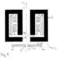
- An objective lens according to the invention is shown schematically in Fig. 1. The objective lens comprises a
magnetic lens 2 and anelectrostatic lens 20. A beam of chargedparticles 30 enters theobjective lens 1 at the top A ofmagnetic lens 2 and, after having been focused bymagnetic lens 2 andelectrostatic lens 20, exits the objective lens at the bottom B ofelectrostatic lens 20. In a typical example shown in Fig. 1, the magnetic lens comprises an iron circuit energized byexcitation coil 6. The maximum magnetic flux density of the magnetic lens is concentrated between thelower pole piece 10 and theupper pole piece 8 of the iron core. This magnetic flux can be increased by increasing the product of the coil windings and the excitation current NI (ampere turns) to magnetize the pole pieces. The focal length may be changed over a certain range by altering the excitation current. - In some applications, scanning coils 14 are supplied. A varying voltage produced by a scanning generator (not shown) creates a magnetic field that deflects the beam of charged particles back and forth in a controlled pattern. Furthermore, the magnetic lens may optionally comprise correction coils 16 for compensating the effects of imperfections of the optical system. The lens properties for a given charged particle energy can be specified (among others) in terms of three parameters: the bore diameter of the pole pieces, the pole spacing and the product of the coil windings and the excitation current NI. The
magnetic lenses 2 used in applications according to the present invention, preferably have abore diameter 12 of bigger than 5 mm to prevent excessive interactions of the charged particles with the magnetic lens. - After the charged particle beam has passed the
magnetic lens 2 it enters theelectrostatic lens 20. In the embodiment shown, the electrostatic lens comprises two electrodes, a firstupper electrode 22 and a secondlower electrode 24. In the embodiment shown, both of the electrodes are substantially flat and circular with abore 26 in their center. In the preferred embodiment, the center bore of one electrode has a diameter of less than 1,2 mm. Further miniaturized electrodes may have a diameter of less than 0,9 mm. Thegap 28 between the electrodes should preferably be smaller than 1,2 mm. However, it is preferred to use a gap width of less than 0,9 mm. Contrary togap 28, the distance between the lower pole piece of the magnetic lens and the upper electrode of the electrostatic lens is not as critical for the focusing properties of the objective lens. The outer diameters of the electrodes are not a critical parameter either. - The combination of the first focusing magnetic lens followed by the second focusing electrostatic lens allows a considerable reduction of the distance between the principal plane of the objective lens and the specimen and achieves a high resolving power. Thereby, the magnetic lens has the advantage of being able to perform a fine focusing without influencing the field above the sample surface. In addition, due to its miniaturization, the electrostatic lens has the advantage of further reducing the focal length. This shifts the principal plane of the objective lens closer to the sample. The objective lens system is not limited to a narrow range of primary energies of the charged particles. It can operate at low and high particle energies. Also, all kinds of scanning and correcting devices can be used together with the objective lens according to Fig. 1, if the desired application should require the use of such devices. In the embodiment shown, the scanning and correction coils are included into the finely focusing magnetic lens. Therefore, the coarsely focusing electrostatic lens can be further miniaturized.
- It is preferred to arrange the miniaturized electrostatic lens directly before the specimen onto which the beam of charged particles is focused. Due to its small dimensions and its small focal length, lens defects are minimized. It is possible to use one or several electrodes for the electrostatic lens. In fact, as many electrodes as desired can be used, however, it is preferred to use at least two electrodes. This ensures sufficient focusing properties for the second focusing electrostatic lens.
- In operation, the beam of charged particles is focused by the combined objective lens system. In a first step, the beam is coarsely focused by the second focusing electrostatic lens e.g. by adjusting the voltage applied to one or more of its electrodes. Thereby, the focal length of the objective lens is altered so that it roughly coincides with the distance between the objective lens and the location of the specimen to be examined. In a second step, the magnetic lens is used for finely focusing the beam of charged particles. Such a fine adjustment may be, for example, required by variations in the surface structure of the specimen. This focusing approach has the advantage of maintaining a constant electric field at the specimen surface. Thus, images are obtained without excessive influence and artifacts due to variations of the electrical field prevailing on the specimen. Also, since the fine focusing of the charged beam of particles on the specimen is done by varying the magnetic field of the first focusing lens, charging effects caused by high electrostatic fields are prevented.
- The electrodes of the electrostatic lens in the embodiment shown in Fig. 1 are substantially flat and horizontal. This allows further minimization of the electrostatic lens and thus, the objective lens system. It is, however, within the scope of the invention to use electrodes having an angle of inclination with respect to the plane perpendicular to the optical axis. Such an arrangement may be preferred, for example, in combination with certain detectors for secondary products caused by the charged particles impinging on the specimen.
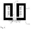
- Fig. 2 shows an alternative embodiment of an objective lens according to the present invention. As in Fig. 1, the objective lens is a combination of a
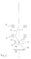
magnetic lens 2 and a miniaturizedelectrostatic lens 20. An iron circuit energized bycoil 6 creates a focusing magnetic field betweenupper pole piece 8 andlower pole piece 10. The magnetic lens further includes scanning coils 14 for deflecting the beam of chargedparticles 30. There are no correction coils shown in Fig. 2. Different from the objective lens shown in Fig. 1, theupper electrode 22 ofelectrostatic lens 20 is integrated into thelower pole piece 10 ofmagnetic lens 2. Such an arrangement further minimizes the overall dimensions of the objective lens. The bore diameter of the magnetic pole pieces is preferably bigger than 5 mm. The diameter of the center bore of the upper andlower electrodes gap width 28 are the same as the respective dimensions in Fig. 1. The thickness ofupper electrode 22 is chosen so that it does not influence the magnetic properties ofmagnetic lens 2 too strongly. Preferably, a thickness comparable to thegap width 28 is used. - Fig. 3 shows a double deflection scan system which pivots the charged
particle beam 30 about the center of the miniaturizedelectrostatic lens 20.Upper deflection coil 32 tilts the beam of chargedparticles 30 from the optical axis 31 and thelower deflection coil 34 tilts the charged particle beam back toward the optical axis 31. Only the coils producing deflections in the plane of the paper are shown. The deflection coils 32, 34 in the arrangement of Fig. 3, when energized by a suitable scan generator, cause the beam to pivot about the center of the miniaturizedelectrostatic lens 20. The beam is thus made to deflect over the specimen in the form of a raster. The raster action is similar to that which takes place in a television tube where the beam sweeps the screen. Having thepivot point 40 in the center of the electrostatic lens, or in close vicinity to the electrostatic lens, allows to scan a larger area on thespecimen 36 without having to increase the center bores of the upper andlower electrodes gap width 28 between these electrodes. - Another useful facility (not shown in Fig. 3) desirable in certain applications is that of beam chopping i.e. the ability to turn the beam on and off in a controlled way over a range of frequencies. Such a chopping stage can be arranged near the charged particle source of the apparatus.
Claims (9)
- Objective lens 1 for focusing a charged particle beam 30 onto a specimen comprising:a first focusing lens 2 positioned between a charged particle source and the specimen for finely focusing the beam of charged particles on the specimen;a second focusing lens 20 positioned between said first focusing lens 2 and the specimen for coarsely focusing the beam of charged particles on the specimen; andthe second focusing lens 20 being an electrostatic lens.
- The objective lens according to claim 1, wherein the first focusing lens 2 is a magnetic lens.
- The objective lens according to any of the preceding claims , wherein the electrodes 22, 24 of the electrostatic lens are miniaturized.
- The objective lens according to any of the preceding claims , wherein the electrostatic lens comprises at least two electrodes 22, 24.
- The objective lens according to claim 4, wherein the inner bore 26 of the at least two electrodes of the electrostatic lens is smaller than 1.2 mm, preferably 0.9 mm.
- The objective lens according to any of claims 4 to 5 , wherein the gap 28 between the at least two electrodes of the electrostatic lens is smaller than 1.2 mm, preferably smaller than 0.9 mm.
- The objective lens according to any of the preceding claims wherein the pivot point 40 of the charged particle beam 30 is situated in close vicinity to the second lens.
- The objective lens according to any of the preceding claims wherein the first focusing lens comprises correcting and/or scanning elements.
- Method for focusing a charged particle beam onto a specimen comprising the following steps:finely focusing the charged particle beam with a first lens positioned between the charged particle source and the specimen; andcoarsely focusing the charged particle beam with a second electrostatic lens interposed between the first lens and the specimen.
Priority Applications (2)
| Application Number | Priority Date | Filing Date | Title |
|---|---|---|---|
| EP98118175A EP0989583A1 (en) | 1998-09-25 | 1998-09-25 | Method and device for focusing a charged particle beam |
| US09/397,803 US6555824B1 (en) | 1998-09-25 | 1999-09-16 | Method and device for focusing a charged particle beam |
Applications Claiming Priority (1)
| Application Number | Priority Date | Filing Date | Title |
|---|---|---|---|
| EP98118175A EP0989583A1 (en) | 1998-09-25 | 1998-09-25 | Method and device for focusing a charged particle beam |
Publications (1)
| Publication Number | Publication Date |
|---|---|
| EP0989583A1 true EP0989583A1 (en) | 2000-03-29 |
Family
ID=8232686
Family Applications (1)
| Application Number | Title | Priority Date | Filing Date |
|---|---|---|---|
| EP98118175A Withdrawn EP0989583A1 (en) | 1998-09-25 | 1998-09-25 | Method and device for focusing a charged particle beam |
Country Status (2)
| Country | Link |
|---|---|
| US (1) | US6555824B1 (en) |
| EP (1) | EP0989583A1 (en) |
Families Citing this family (5)
| Publication number | Priority date | Publication date | Assignee | Title |
|---|---|---|---|---|
| JP2000003847A (en) * | 1998-06-15 | 2000-01-07 | Canon Inc | Charged particle beam contraction transfer apparatus and manufacture of the apparatus |
| US20090159810A1 (en) | 2005-11-28 | 2009-06-25 | Rainer Knippelmeyer | Particle-Optical Component |
| EP1970935B1 (en) * | 2007-03-14 | 2011-01-12 | ICT, Integrated Circuit Testing Gesellschaft für Halbleiterprüftechnik mbH | Lens coil cooling of a magnetic lens |
| GB0912332D0 (en) * | 2009-07-16 | 2009-08-26 | Vg Systems Ltd | Magnetic lens,method for focussing charged particles and charged particle energy analyser |
| JP6080540B2 (en) * | 2012-12-26 | 2017-02-15 | 株式会社ニューフレアテクノロジー | Charged particle beam lithography system |
Citations (3)
| Publication number | Priority date | Publication date | Assignee | Title |
|---|---|---|---|---|
| JPS61101944A (en) * | 1984-10-25 | 1986-05-20 | Nippon Telegr & Teleph Corp <Ntt> | Charged particle beam focusing system |
| EP0721201A1 (en) * | 1994-12-19 | 1996-07-10 | Opal Technologies Ltd. | System for high resolution imaging and measurement of topographic and material features on a specimen |
| EP0790634A1 (en) * | 1996-02-16 | 1997-08-20 | ACT Advanced Circuit Testing Gesellschaft für Testsystementwicklung mbH | Electrostatic-magnetic lens arrangement |
Family Cites Families (3)
| Publication number | Priority date | Publication date | Assignee | Title |
|---|---|---|---|---|
| GB2115976A (en) * | 1982-02-26 | 1983-09-14 | Philips Electronic Associated | Charged particle beam apparatus |
| JPH071681B2 (en) * | 1990-04-19 | 1995-01-11 | 株式会社日立製作所 | Charged particle beam device |
| DE69633338T2 (en) * | 1996-11-19 | 2005-02-24 | Advantest Corp. | Electrostatic device for acting on a corpuscular beam |
-
1998
- 1998-09-25 EP EP98118175A patent/EP0989583A1/en not_active Withdrawn
-
1999
- 1999-09-16 US US09/397,803 patent/US6555824B1/en not_active Expired - Lifetime
Patent Citations (3)
| Publication number | Priority date | Publication date | Assignee | Title |
|---|---|---|---|---|
| JPS61101944A (en) * | 1984-10-25 | 1986-05-20 | Nippon Telegr & Teleph Corp <Ntt> | Charged particle beam focusing system |
| EP0721201A1 (en) * | 1994-12-19 | 1996-07-10 | Opal Technologies Ltd. | System for high resolution imaging and measurement of topographic and material features on a specimen |
| EP0790634A1 (en) * | 1996-02-16 | 1997-08-20 | ACT Advanced Circuit Testing Gesellschaft für Testsystementwicklung mbH | Electrostatic-magnetic lens arrangement |
Non-Patent Citations (2)
| Title |
|---|
| FROSIEN J ET AL: "COMPOUND MAGNETIC AND ELECTROSTATIC LENSES FOR LOW-VOLTAGE APPLICATIONS", JOURNAL OF VACUUM SCIENCE AND TECHNOLOGY: PART B, vol. 7, no. 6, 1 November 1989 (1989-11-01), pages 1874 - 1877, XP000117179 * |
| PATENT ABSTRACTS OF JAPAN vol. 010, no. 283 (E - 440) 26 September 1986 (1986-09-26) * |
Also Published As
| Publication number | Publication date |
|---|---|
| US6555824B1 (en) | 2003-04-29 |
Similar Documents
| Publication | Publication Date | Title |
|---|---|---|
| US6218664B1 (en) | SEM provided with an electrostatic objective and an electrical scanning device | |
| US8319192B2 (en) | Charged particle apparatus | |
| EP2128887B1 (en) | TEM with aberration corrector and phase plate | |
| JP6554288B2 (en) | Charged particle beam equipment | |
| EP1150327A1 (en) | Multi beam charged particle device | |
| US7067820B2 (en) | Particle-optical apparatus with a permanent-magnetic lens and an electrostatic lens | |
| KR20070116260A (en) | Electron beam | |
| EP1057203B1 (en) | Particle-optical apparatus involving detection of auger electrons | |
| EP0708975B1 (en) | Particle-optical apparatus comprising a detector for secondary electrons | |
| CN108807118B (en) | A scanning electron microscope system and a sample detection method | |
| EP2405460B1 (en) | Electron beam device with tilting and dispersion compensation, and method of operating same | |
| JP3372138B2 (en) | Scanning electron microscope | |
| US3717761A (en) | Scanning electron microscope | |
| US20020109089A1 (en) | SEM provided with an adjustable final electrode in the electrostatic objective | |
| US20030075686A1 (en) | Column for a charged particle beam device | |
| US6653632B2 (en) | Scanning-type instrument utilizing charged-particle beam and method of controlling same | |
| US6555824B1 (en) | Method and device for focusing a charged particle beam | |
| JP3474082B2 (en) | Electron beam equipment | |
| US6717141B1 (en) | Reduction of aberrations produced by Wien filter in a scanning electron microscope and the like | |
| CN114300325A (en) | Charged particle beam device and adjustment method | |
| WO2016132487A1 (en) | Charged particle beam device and aberration corrector | |
| US20020079449A1 (en) | SEM having a detector surface segmented into a number of separate regions | |
| US20220384140A1 (en) | Method for operating a particle beam device, computer program product and particle beam device for carrying out the method | |
| JPS5945173B2 (en) | scanning electron microscope |
Legal Events
| Date | Code | Title | Description |
|---|---|---|---|
| PUAI | Public reference made under article 153(3) epc to a published international application that has entered the european phase |
Free format text: ORIGINAL CODE: 0009012 |
|
| AK | Designated contracting states |
Kind code of ref document: A1 Designated state(s): AT BE CH CY DE DK ES FI FR GB GR IE IT LI LU MC NL PT SE |
|
| AX | Request for extension of the european patent |
Free format text: AL;LT;LV;MK;RO;SI |
|
| AKX | Designation fees paid | ||
| REG | Reference to a national code |
Ref country code: DE Ref legal event code: 8566 |
|
| STAA | Information on the status of an ep patent application or granted ep patent |
Free format text: STATUS: THE APPLICATION IS DEEMED TO BE WITHDRAWN |
|
| 18D | Application deemed to be withdrawn |
Effective date: 20000930 |